

Page 1
VS-10S
SERVICE MANUAL
Page 2

CONTENTS
1 SPECIFICATION
2 OPERATING INSTRUCTIONS
3 IMPORTANT SAFEGUARDS
4 ADJUSTMENT PROCEDURE
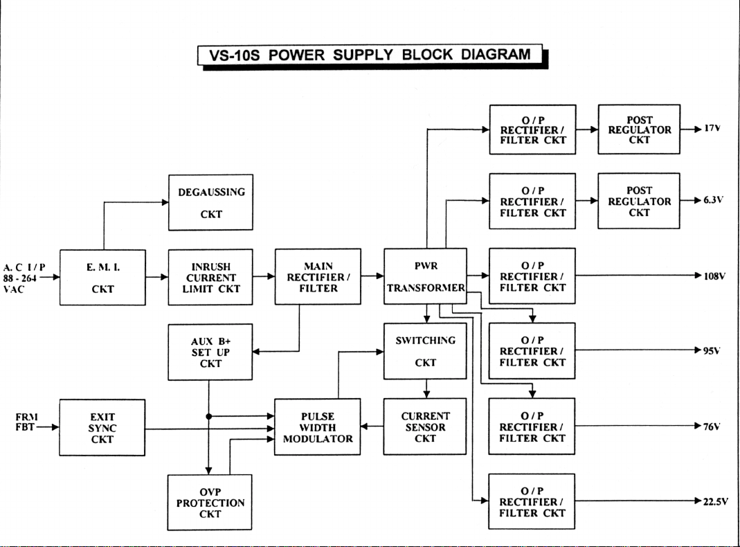
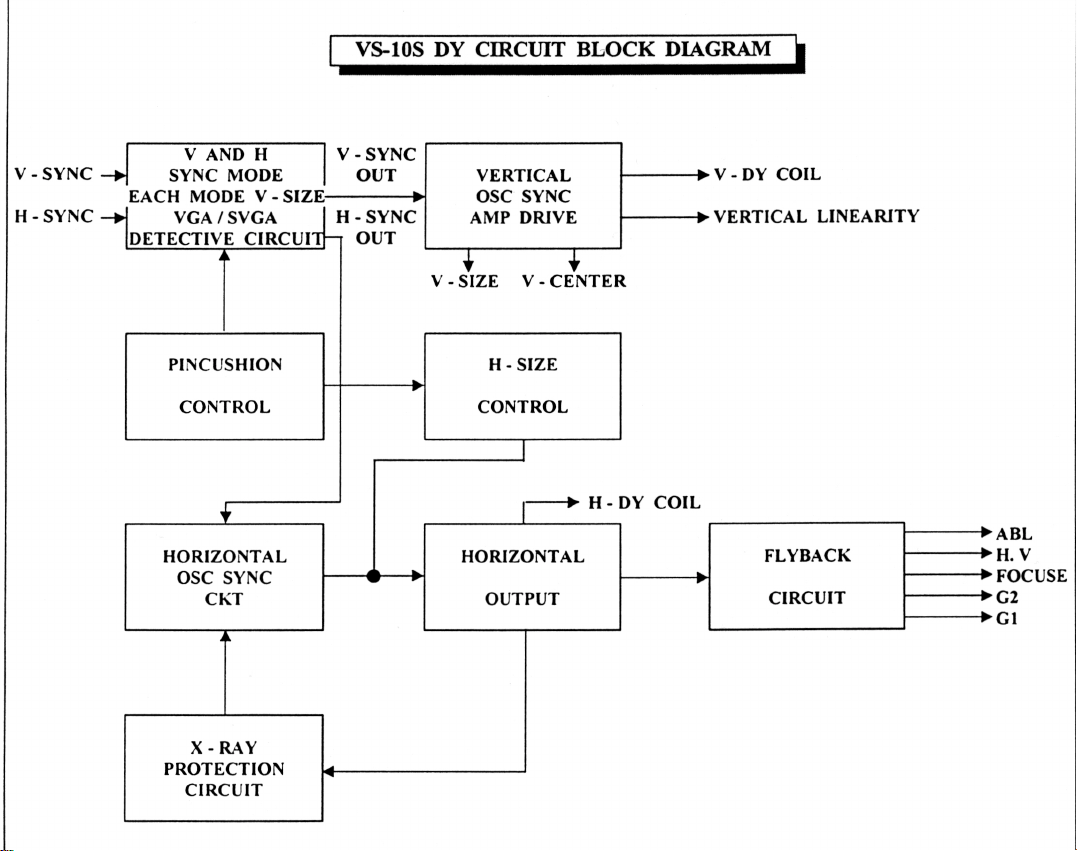
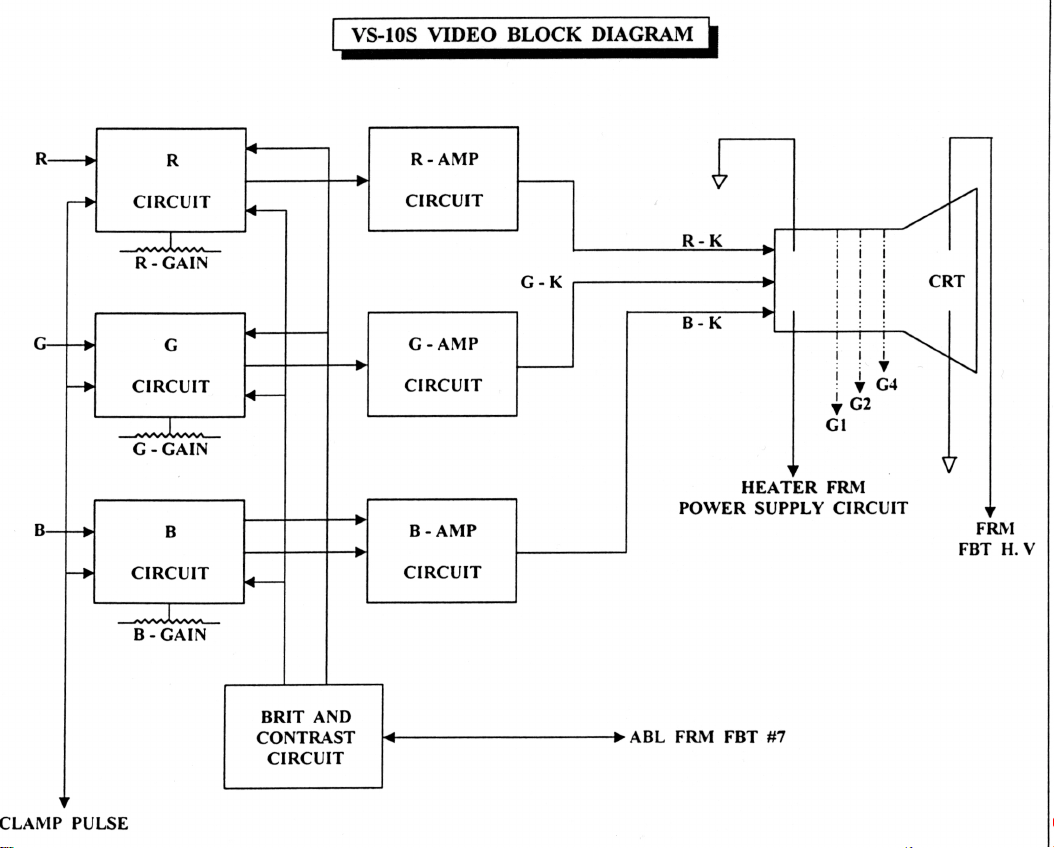
5 BLOCK DIAGRAM
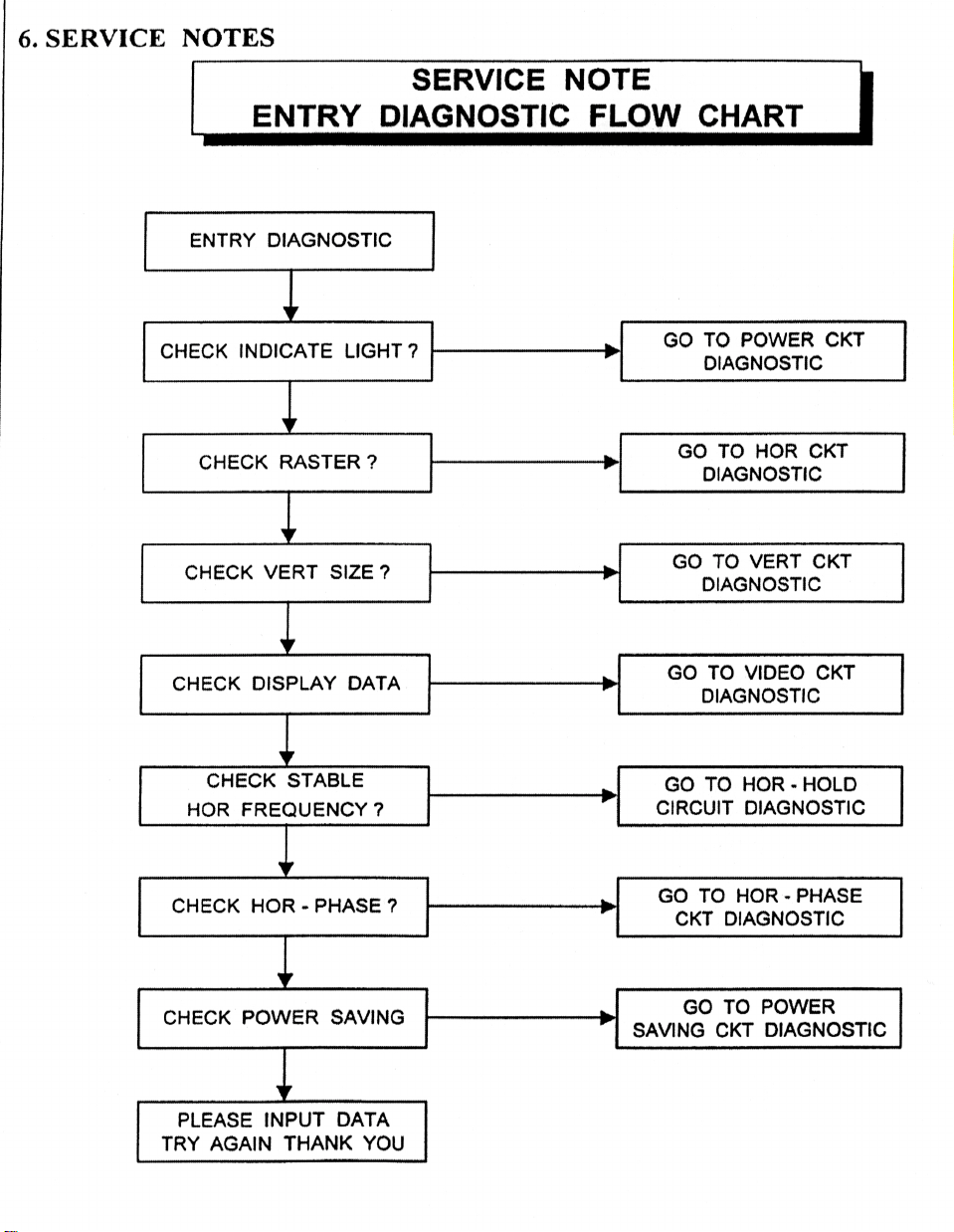
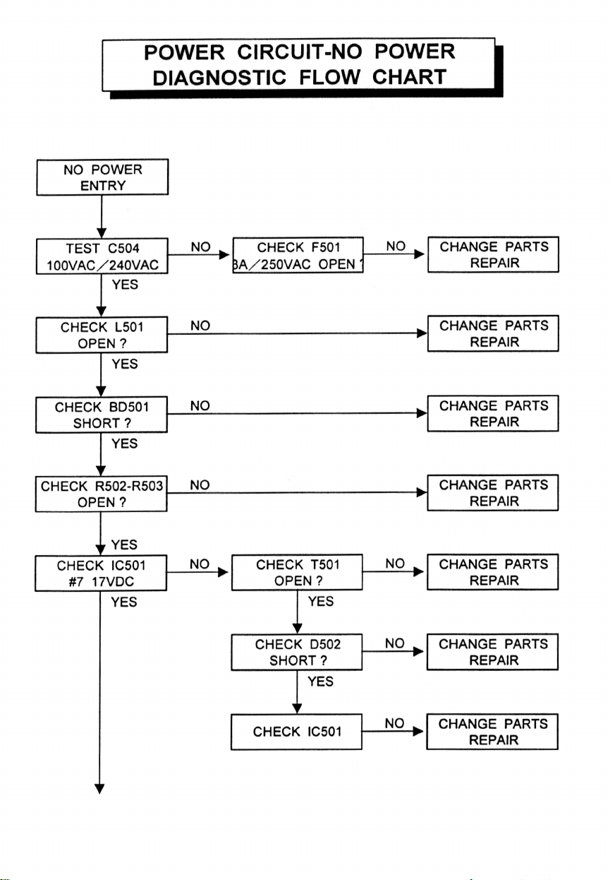
6 SERVICE NOTES
7 CIRCUIT DIAGRAM
8 LAYOUT DIAGRAM
9 EXPLODED DRAWING
10 PARTS LIST
Page 3

1 SPECIFICATION
10” Mono Chrome Monitor
CRT SIZE : 10” (9V)
DOT PITCH : 0.26
DEFLECTION ANGLE : 90º
SCAN FREQ. : HOR. 31.5KHz, 35KHz, 38 KHz
VER. 50 ~ 90 Hz
RESOLUTION : 640 x 480, 800 x 600, 1024 x 768
BANDWIDTH : 26 MHz, 35 MHz, 45MHz
VIDEO SIGNAL : VIDEO ANALOG 0.7V/75Ω
SYNC INPUT TYPE : H - SYNC, V - SYNC TTL
INPUT CONNECTOR : 15 PIN D SHELL
USER CONTROL : BRI, CON, POWER SW, V - SIZE,
H - SIZE, V – CENTER
INPUT VOLTAGE : AC 100 ~ 240V, 50 ~ 60 Hz (AUTO)
POWER CONSUMPTION : 68W MAX.
DIMENSION : 257W x 270H x 300D mm
NET WEIGHT : 6.8 Kg
SAFETY : UL, CUL, DHHS, TÜV – GS
EMI : FCC – B, CE
Page 4

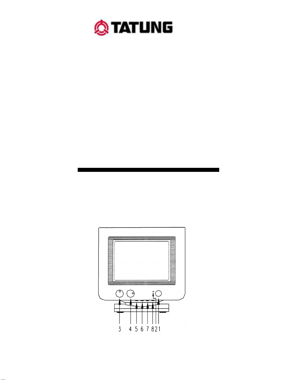
2 OPERATING INSTRUCTIONS
2-1 POWER SWITCH
Turn on the power switch on your PC system. Then turn on the power of
the monitor by pressing the switch on the front of the unit.
2-2 POWER INDICATOR
A green indicator LED indicated the power is on. An orange indicator L E D
indicates the power is in power saving mode.
2-3 BRIGHTNESS ADJUSTMENT
Adjust the control to get the desired level of brightness. Rotate clockwise
for brighter on the background.
2-4 CONTRAST ADJUSTMENT
Adjust the control to get the desired level of contrast. Rotate clockwise to
get more contrast.
2-5 HORIZONTAL-SIZE ADJUSTMENT
Adjust the control to get adequate horizontal size. Rotate clockwise to get a
fuller display size.
2-6 VERTICAL-SIZE ADJUSTMENT
Adjust the control to get adequate vertical size. Rotate clockwise to get a
larger display size.
2-7 VERTICAL-CENTER ADJUSTMENT
Adjust the control to get adequate vertical position. Rotate clockwise to
move the screen up.
2-8 HORIZONTAL-PHASE ADJUSTMENT
Adjust the control to get adequate horizontal position. Rotate clockwise to
reposition to the right.
Page 5

3 IMPORTANT SAFEGUARDS
For your own safety, read all of these instructions and save them for later
reference.
3-1 POWER PLUG
This display monitor is equipped with a 3-wire grounding type power plug.
The third pin provides a safety ground for the display frame and will fit
only into the power outlet of compatible configuration.
Contact your technician to replace the obsolete outlet. Do not defeat the
safety purpose of the grounding plug.
3-2 POWER INPUT
This display should be operated only from the types of power source
indicated on the label. If there is any question about the type of power
supplied to the outlet, consult your technician or dealer.
3-3 VENTILATION
Openings on the cabinet back and bottom are provided for ventilation. To
insure reliable operation and to protect the display from overheating, these
openings must not be blocked or covered. Do not place the display near or
over a radiator or heating vent. If this unit is installed within another
enclosure be sure that adequate ventilation has been provided.
Never push objects of any kind through the cabinet openings. They may
touch dangerous voltage points or cause short circuits that could result in
fire or electrical shock.
3-4 ATTACHMENTS
Signal sources must be of approved types, properly grounded, if safety
standards are to be maintained ask the service technician to perform routine
safety tests to determine that all equipment is in safe operating condition.
Overloaded or poorly grounded AC power systems can cause severe
difference in ground potential between the display and the signal source.
Particularly on long video lines where the display and the source are
plugged into different AC power circuits. Besides causing signal
instability, ground potential may be great enough to present a shock hazard.
Ground potential test should be a part of the routine safety check carried out
by the service technician.
Page 6

3-5 CLEANING
Unplug the power cord from the outlet before cleaning the display . Use
only a damp cloth and mild detergent. Do not use strong liquid cleaner or
aerosol sprays. Do not attempt to clean the interior of the unit: this action
must be performed by the service technician as required during normal
maintenance.
3-6 SERVICE
Removal of the back by an unauthorised person may expose the user to
dangerous voltage or other hazards.
Refer all servicing to qualified service personnel. Unplug the display from
the power outlet and notify the service technician should any of the
following occur
(a) If liquid has been spilt into the display
(b) If the display has been exposed to rain or water
(c) If the display has been dropped or the cabinet damaged
(d) If fuses continue to blow
(e) If the power cord is damaged or frayed
(f) If a distinct change from normal operation is apparent.
Page 7

4 ADJUSTMENT PROCEDURE
This alignment procedure is for adjusting/testing picture performance, in
order to obtain the optimum result, the following adjustment sequence must
be followed step by step:
4-1 Check B+ voltage:
a. Test pattern: 640 x 480 cross-hatch.
b. Set up external brightness and contrast VR to central position.
c. Adjusted VR501 have 95Vdc ± 0.5Vdc use digital multimeter
positive leader test J9 positive point, negative leader to ground.
4-2 Vertical linearity adjustment:
a. Test pattern: 640 x 480 cross-hatch.
b. Set up external brightness and contrast VR to central position.
c. Adjust VR302 to make equal distance between top-center and
bottom-center.
4-3 Horizontal-hold adjustment:
a. Test pattern: 640 x 480 cross-hatch.
b. Set up external brightness and contrast VR to central position.
c. Turn off horizontal-sync (pin to ground)
d. Adjust VR602 to ma ke pattern upright.
4-4 Pin-cushion adjustment:
a. Test pattern: 640 x 480 cross-hatch.
b. Set up external brightness and contrast VR to central position.
c. Adjust VR304 make picture to top and bottom ≤ 2mm, left and right
≤ 2mm.
4-5 Brightness adjustment:
a. Test pattern: 640 x 480 full-white.
b. Set up external brightness and contrast VR to maximum.
c. Test R251, then adjust VR701 to –20Vdc ± 0.1Vdc.
4-6 X-ray protection adjustm e nt:
a. Test pattern: 640 x 480 cross-hatch.
b. Test TP2, then adjust VR 603 to 5.2 Vdc ± 0.1Vdc.
Page 8

4-7 White balance adjustment:
a. Test pattern: 640 x 480 “ 2” balance.
b. Set up external brightness and contrast VR to maximum.
c. Adjust VR240, VR243, VR241 have R.G.B. cathode to 55Vdc.
d. Turn external brightness VR to minimum.
e. Set VR209 to central position.
f. Adjust VR245, V R244, VR248 have R.G.B cathode to 30V p-p.
4-8 White balance adjustment:
a. Test pattern: 640 x 480 full-white.
b. Set up external brightness to center.
c. Turn external contrast VR to 2FL.
d. Adjust VR240, VR 243, VR241 to X = 281 ± 15 m m,
Y = 298 ± 15 mm.
e. Turn external contrast to maximum.
f. Adjust VR245, VR244, VR248 to X = 281 ± 15 mm,
Y = 298 ± 15 mm.
4-9 Raster brightness adjustment:
a. disconnect video signal.
b. External brightness to maximum.
c. Adjust FBT screen VR to 0. 5 ~ 1.5 FL.
4-10 Full-white adjustment:
a. test pattern: 640 x 480 full-white.
b. Set up external brightness VR to center, external contrast VR to
maximum.
c. Adjust VR212 have luminance equal to 25 ~ 45 FL.
4-11 Purity check:
a. test pattern: 640 x 480 full-white
b. set up external brightness and contrast VR to maximum position.
c. Change to Red/Green/Blue colour for every check if purity is good.
4-12 Misconvergence check:
a. test pattern: 640 x 480 cross-hatch
b. use klein optica convergence gauge change to R/B, R/G, B/G colour
for every check misconvergence.
c. center area (d = 0.15 mm ) , A zone, B zone (0.4mm).
Page 9
Page 10
Page 11
Page 12
Page 13
Page 14

Page 15

Page 16

Page 17

Page 18

Page 19

Page 20

Page 21

Page 22

Page 23

Page 24

Page 25

Page 26

Page 27

Page 28

Page 29

Page 30

Page 31

Page 32

Page 33

Page 34

Page 35

Page 36

Page 37

Page 38

10 PARTS LIST
PCB
LOCATION P/N LOCATION P/N LOCATION P/N
PCB 010-1013-111 PCB 010-2003-111 PCB 010-6003-111
RESISTORS
LOCATION P/N LOCATION P/N LOCATION P/N
R201 75R 011-0750-127 R254 10K 011-0103-127 R503 47K 3W 013-0473-325
R202 75R 011-0750-127 R255 10K 011-0103-127 R504 013-0333-225
R203 75R 011-0750-127 R301 22K 011-0223-127 R505 47K 3W 013-0473-322
R204 10K 011-0103-127 R302 10K 011-0103-127 R506 10R 011-0100-227
R205 10K 011-0103-127 R303 4K7 011-0473-127 R507 47K 011-0473-227
R206 10K 011-0103-127 R304 1M 011-0105-127 R508 47R 011-0470-227
R207 100R 011-0101-127 R305 270K 011-0274-127 R509 1K 011-0102-127
R208 3K 011-0302-127 R306 110K 011-0114-127 R510 OIR33 2W 013-0338-225
R209 2K7 011-0272-127 R307 1M 011-0105-127 R511 33K 011-0333-127
R210 330R 011-0331-127 R308 200K 011-0114-127 R512 47R 011-0470-227
R211 1K8 011-0182-127 R309 011-0253-127 R513 470R 011-0471-227
R212 3K9 011-0392-127 R310 1R 1N 013-0137-121 R514 56R 011-0560-227
R213 750R 011-0751-127 R311 1K2 011-0122-127 R515 1M 011-0105-127
R214 390R 011-0391-127 R312 120R 011-0121-127 R516 100K 011-0104-127
R215 390R 011-0391-127 R313 2K7 011-0272-127 R517 15K 011-0153-127
R216 150R 011-0151-127 R314 011-0227-327 R518 100R 011-0101-227
R217 120R 011-0121-127 R315 330R 011-0331-327 R519 1K 011-0102-127
R218 390R 011-0391-127 R316 10K 011-0103-127 R521 10K 011-0103-227
R219 390R 011-0391-127 R317 150K 011-0154-127 R522 82K 011-0823-227
R220 47R 011-0470-127 R318 1RS 1W 013-0157-121 R523 330R 5W 015-0331-222
R221 150R 011-0151-127 R319 100R 013-0101-121 R524 4R7 013-0477-120
R222 120R 011-0121-127 R320 3K9 011-0392-127 R526 3K3 011-0332-127
R223 47R 011-0470-127 R321 22K 011-0223-127 R527 013-0827-322
R224 47R 011-0470-127 R322 56K 011-0563-127 R528 47R 011-0470-127
R225 390R 011-0391-127 R323 22K 011-0223-127 R601 82K 011-0623-127
R226 390R 011-0391-127 R324 43K 011-0433-127 R602 10K 011-0103-127
R227 150R 011-0151-127 R325 3K3 011-0332-127 R603 63.4K 012-6332-207
R228 120R 011-0121-127 R326 1K5 011-0152-127 R604 2K2 011-0222-127
R229 100R 011-0101-327 R327 1K2 011-0122-127 R605 22K 011-0223-127
R230 1K5 013-0152-322 R328 4K7 011-0472-127 R606 12K 011-0123-127
R231 47R 011-0470-127 R329 4K7 011-0472-127 R607 3K3 011-0332-127
R232 27K 011-0273-127 R330 15K 011-0153-127 R608 12K 011-0113-127
R233 1K5 013-0152-322 R331 750R 011-0751-127 R609 10K 011-0103-127
R234 47R 011-0470-127 R332 47K 011-0473-127 R610 33R 011-0333-127
R235 27K 011-0273-127 R333 18K 011-0682-127 R611-8K2 011-0822-127
R236 1K5 013-0152-322 R334 100K 011-0104-127 R612 1K 011-0102-127
R237 47R 011-0470-127 R338 150K 011-0154-127 R613 13K 011-0133-127
R238 27K 011-0273-127 R339 15K 011-0153-127 R614 4R7 011-0477-127
R242 220R 011-0221-327 R340 6K8 011-0682-127 R615 15K 011-0163-127
R246 220R 011-0221-327 R341 2K4 012-2400-107 R616 13.2K 012-1332-207
R250 220R 011-0221-327 R343 2K 012-2001-107 R617 2K2 011-0222-127
R251 10R 011-0100-327 R501 560K 011-0564-327 R618 3K3 011-0332-127
R252 3K3 013-0332-026 R502 47K 3W 013-0473-322 R619 3K3 011-0332-227
Page 39

RESISTORS
LOCATION P/N LOCATION P/N LOCATION P/N
R620 8K2 011-0822-227 R713 1K 011-0102-127 R815 10K 011-0103-127
R621 2K 011-0202-227 R714 10K 011-0103-127 R816 10K 011-0103-127
R622 220R 013-0221-225 R715 4R7 013-0477-120 R817 820R 011-0821-227
R623 470R 011-0471-227 R716 1M 011-0105-127 R818 4K7 011-0472-127
R624 1R 013-0107-225 R717 18K 011-0183-127 R819 3K3 011-0332-127
R625 4R7 011-0470-227 R718 180K 011-0184-227 R820 1K 011-0102-127
R626 330 1W 013-0331-121 R719 100K 011-0104-127 R821 3K9 011-0392-127
R627 150R 013-0151-121 R720 100R 011-0101-127 R822 2K4 011-0242-127
R701 4K7 011-0472-127 R802 330R 013-0331-121 R823 2K4 011-0242-127
R702 2K2 011-0222-127 R803 680R 011-0681-127 R824 2K2 011-0222-127
R703 2K2 011-0103-327 R804 330R 011-0331-127 R825 1K 011-0102-127
R704 82K 011-0823-127 R805 4K7 011-0472-127 R830 011-0823-127
R705 2K2 011-0222-127 R806 1M 011-0105-127 D205 011-0182-127
R706 680R 011-0681-127 R808 82K 011-0823-127 J207 013-0187-221
R707 8K2 011-0822-127 R809 56K 011-0563-127 Q805 011-0102-227
R708 330R 011-0331-127 R810 27K 011-0273-127 NR801 017-0332-520
R710 10K 011-0103-127 R811 5K 011-0512-127 PTC501 018-0140-060
R711 1K 011-0102-227 R813 10K 011-0103-127 NTC501 019-0100-050
R712 100K 011-0104-227 R814 1K 011-0102-127
CAPACITORS
LOCATION P/N LOCATION P/N LOCATION P/N
C201 407uF 050-4782-501 C229 10uF 050-1002-501 C318 33uF 050-3302-251
C202 4.7 uF 050-4782-501 C231 103P 051-1037-350 C319 051-1026-310
C203 4.7 uF 050-4782-501 C233 103P 051-1037-350 C320 052-4705-110
C204 104P 051-1048-170 C235 103PF 051-1037-350 C321 100uF 050-1012-251
C205 104P 051-1048-170 C236 103P 051-1037-553 C322 050-4702-351
C206 104P 051-1048-170 C237 1N 051-1026-310 C323 050-4702-351
C207 4.7uF 050-4782-501 C241 051-1037-350 C325 050-2212-161
C210 104pF 051-1048-170 C242 47uF 050-4702-161 C326 051-1048-170
C211 104pF 051-1048-170 C243 050-4702-845 C327 33uF 050-1002-351
C212 104pF 051-1048-170 C301 0.33uF 055-3345-500 C328 104P 051-1048-170
C213 100uF 050-1012-251 C302 0.1uF 053-1045-500 C329 33uF 050-3302-251
C215 104P 051-1048-170 C303 1uF 050-1082-501 C418 051-1048-170
C216 100uF 050-1012-251 C306 0.1uF 053-1045-500 C419 050-4712-255
C218 100uF 050-1012-161 C307 0.1uF 053-1045-500 C501 070-2246-888
C219 104pF 051-1048-170 C308 2200uF 050-2222-355 C502 070-1046-885
C220 103pF 051-1037-150 C309 0.1uF 051-1048-170 C504 050-1512-905
C221 180pF 052-1815-110 C310 220uF 050-2212-355 C505 051-2727-452
C222 150pF 052-1515-110 C311 1uF 050-1082-501 C507 050-1012-251
C223 150Pf 052-1515-110 C312 0.33uF 055-2245-500 C508 051-6816-110
C224 10uF 050-1002-501 C313 47uF 050-4702-501 C509 057-2222-500
C225 103P 051-1037-150 C314 220uF 050-2222-165 C510 055-1045-500
C226 10uF 050-1002-501 C315 058-1002-501 C511 051-1016-110
C227 103pF 051-1037-150 C316 0.47uF 055-4745-500 C512 051-1048-170
C228 103pF 051-1037-150 C317 102P 051-1026-110 C513 055-1045-500
C514 071-4727-903 C604 3N3 056-3325-840 C621 47uF 049-4702-865
C515 071-4727-903 C605 1uF 050-1082-501 C622 052-4705-110
C516 051-1026-110 C606 .01uF 053-1035-500 C623 050-1012-251
C517 051-4716-410 C607 1uF 050-1082-501 C624 47uF 050-4702-351
C518 050-1012-865 C608 2n7 056-2725-840 C702 100uF 050-1012-251
C519 049-4702-865 C609 050-1012-161 C703 .47uF 050-4792-501
C520 050-1022-355 C610 050-4702-351 C704 470uF 050-4712-355
C521 050-1022-355 C611 4.7uF 050-4782-501 C705 10uF 050-1002-501
C522 050-1022-355 C612 050-1002-501 C706 47uF 050-4702-501
Page 40

CAPACITORS
LOCATION P/N LOCATION P/N LOCATION P/N
C523 050-4712-256 C613 100uF 050-1012-251 C707 22uF 050-2202-875
C525 071-4727-903 C614 1N 051-1026-110 C708 0.1uF 051-1048-170
C526 071-4727-903 C615 4N3 062-6225-968 C801 050-4712-161
C527 053-2245-840 C616 1uF 055-1055-843 C802 051-1048-170
C528 051-1048-170 C617 1N 051-1026-410 C803 050-2212-161
C531 051-2216-410 C618 0.82uF 063-8245-887 C805 052-4705-110
C601 100pF 051-1016-110 C619 5n6 056-5625-933 C807 051-1037-150
C602 270pF 051-2716-110 C620 0.1uF 051-1048-170 C808 052-4705-110
C603 1N 054-1025-500
IC
LOCATION P/N LOCATION P/N LOCATION P/N
IC201 LM203 112-5501-010 IC303 113-1503-006 IC601 LA7851 112-7010-028
IC301 VA2801 112-9003-021 IC501 UC3842 112-5002-023 IC801 112-2519-024
IC302 CA3080E 112-1027-030
TRANSISTORS
LOCATION P/N LOCATION P/N LOCATION P/N
Q201 IC1906 114-0209-019 Q213 2SB716 114-0108-014 Q504 C1921 114-0208-020
Q202 C945 114-0209-019 Q214 2SA673 114-0008-005 Q601 C458 114-0209-019
Q203 C945 114-0209-019 Q301 C1213 114-0208-017 Q602 D669 114-0308-053
Q204 C945 114-0209-019 Q302 A733 114-0015-006 Q603 C4769 114-0209-071
Q205 2SD1609 114-0308-049 Q303 E© 114-0015-006 Q701 C1213 114-0208-017
Q206 2SD7561 114-0308-054 Q307 D669A 114-0308-053 Q702 B649 114-0108-013
Q207 2SB716 114-0108-014 Q310 C945 114-0209-019 Q705 C945 114-0209-019
Q208 2SD1609 114-0308-049 Q311 A733 114-0015-006 Q801 C1815 114-0209-019
Q209 2SD756 114-0308-054 Q312 A733 114-0015-006 Q802 C1815 114-0209-019
Q210 2SB716 114-0108-014 Q501 K1794 115-0913-010 Q803 C1815 114-0209-019
Q211 2SD1609 114-0308-049 Q502 FOR3G 116-0109-003 Q804 C1815 114-0209-019
Q212 2SD756 114-0308-054 Q503 TIP127 114-0703-072 Q805 C1815 114-0209-019
DIODE
D201 IN4937 119-1023-032 D601 IN4148 117-0117-005 D806 IN4148 117-0117-005
D202 IN4937 119-1023-032 D602 IN4148 117-0117-005 D807 IN4148 117-0117-005
D203 IN4937 119-1023-032 D603 BYT52D 119-1028-027 D808 IN4148 117-0117-005
D204 8.2V 118-1008-013 D604 BYT52D 119-1028-027 D809 IN4148 117-0117-005
D301 IN4148 117-0117-005 D606 BYT56J 119-2305-031 D810 IN4148 117-0117-005
D302 IN 4148 117-0117-005 D607 HEA105 119-1005-014 D811 IN4148 117-0117-005
D303 IN4008 119-1023-009 D608 HEA105 119-2305-031 D812 IN4148 117-0117-005
D501 BYT52M 119-1028-029 D609 HEA105 119-2305-031 ZD301 IN4148 118-0508-008
D502 BYT52M 119-1028-027 D701 IN4148 117-0117-005 ZD501 18V 118-0508-001
D503 IN4148 117-0117-005 D702 IN4148 117-0117-005 ZD601 118-0508-008
D504 BYT56M 119-1505-026 D703 BYT52D 119-1028-027 ZD602 6.2V 118-0508-007
D505 BYT56M 119-1505-026 D704 BYT52G 119-1028-027 ZD701 8R2 118-0508-010
D506 BY56M 119-1505-026 D705 IN4148 117-0117-005 ZD801 501V 118-0508-004
D507 HER205 119-2028-030 D802 IN4148 117-0117-005 BD501 120-2024-001
D508 HER205 119-2028-030 D803 IN4148 117-0117-005
D509 HER205 119-2028-030 D804 IN4148 117-0117-005
D510 IN4148 117-0117-005 D805 IN4148 117-0117-005
Page 41

VR RESISTORS
LOCATION P/N LOCATION P/N LOCATION P/N
R450 130-4501-502 VR245 100B 131-1011-012 VR306 130-3550-500
R451 130-3501-502 VR248 100B 131-1011-012 VR501 131-5022-012
VR239 10K 131-1031-112 VR301 100K 130-4550-500 VR601 10K 130-3550-500
VR240 5K 131-5021-012 VR302 100K 131-1042-012 VR602 5K 131-5022-012
VR241 5K 131-5021-012 VR303 10K 130-3550-500 VR603 1K 131-1022-012
VR243 5K 131-5021-012 VR304 1K 131-1022-012 VR701 300K 131-3042-012
VR244100B 131-1011-012
BASE
LOCATION P/N LOCATION P/N LOCATION P/N
G2 232-0123-001 P205 232-0215-002 P801 232-0406-011
L 232-0123-001 P402 232-0306-010 P802 232-0306-010
N 232-0123-001 P404 232-0306-010 P803 232-0406-011
P201 232-0606-013 P501 232-0215-002 PT2 232-0155-017
P202 232-0406-011
WIRE
LOCATION P/N LOCATION P/N LOCATION P/N
Q303
Q303
B~LA851#2
C~WT8043#7
420-0204-170 420-1014-314 421-1404-007
420-020A-035 420-1064-314 421-1404-008
420-0244-075 421-0303-012 421-1503-009
420-0402-095 421-0303-013 423-7183-150
420-0464-060 421-0303-014 423-7183-150
420-0504-190
TRANSFORMER
LOCATION P/N LOCATION P/N LOCATION P/N
T501 503-1023-215 T601 503-2013-015 T602 503-3021-015
COIL
LOCATION P/N LOCATION P/N LOCATION P/N
J61 534-0000-002 L205 537-4786-226 L506 537-1807-135
L201 537-4786-226 L501 538-0350-503 L507 534-0000-003
L202 537-4786-226 L504 537-1807-135 L601 537-1067-145
L203 537-4786-226 L505 537-1807-135 L602 537-3757-135
L204 537-4786-226
OTHER
LOCATION P/N LOCATION P/N LOCATION P/N
XR801 020-0000-001 Z201 391-0201-002 451-9103-023
SW501 261-0521-401 Z202 391-0201-002 521-3085-641
381-1000-002 Z203 391-0201-002 604-0003-305
Page 42

OTHER
LOCATION P/N LOCATION P/N LOCATION P/N
LED ASS’Y 891-0040-004 USER MANUAL 312-0011-101 POLYFORM 460-0003-240
BASE ASS’Y 891-0050-008 POWER CORD 400-0717-125 PE BAG 470-0010-001
CARTON 305-1278-999 SIGNAL CABLE 410-1207-130 PE BAG 470-0011-003
CARTON 305-3277-001 POLYFORM 460-0001-077 CRT 500-4141-100
 Loading...