

Page 1

VM-14AF
SERVICE MANUAL
Page 2

CONTENTS
1 SPECIFICATION
2 OPERATING INSTRUCTIONS
3 IMPORTANT SAFEGUARDS
4 ADJUSTMENT PROCEDURE
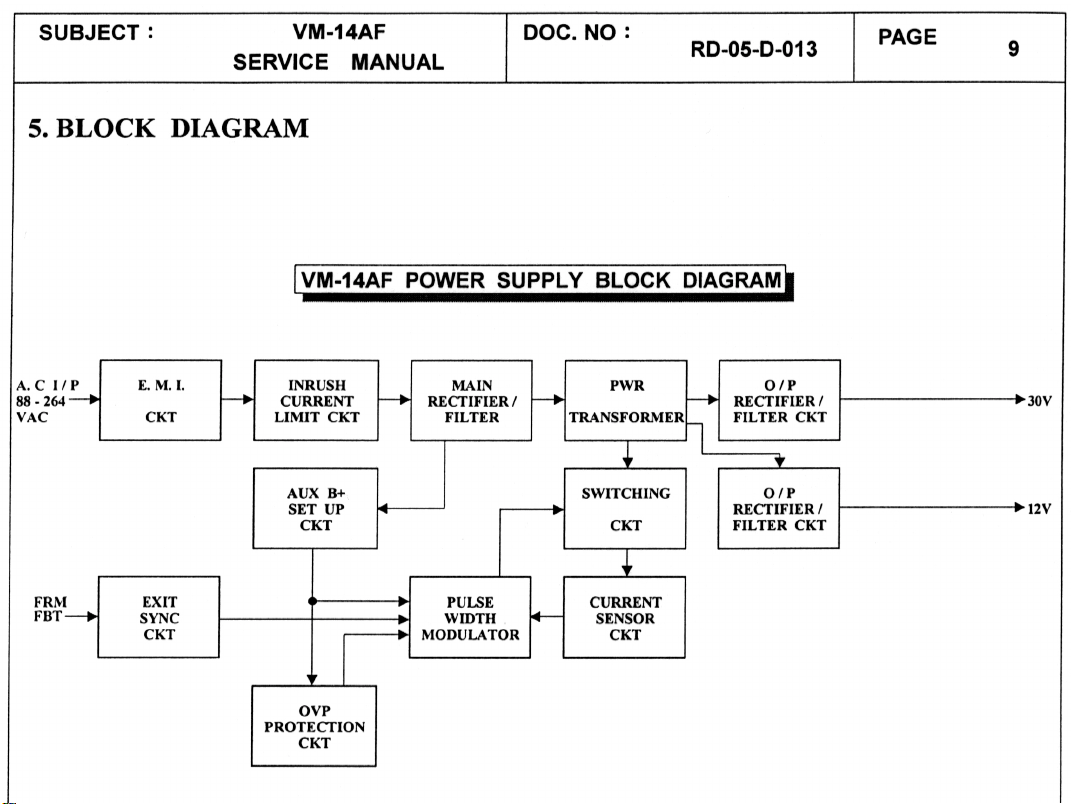
5 BLOCK DIAGRAM
6 SERVICE NOTES
7 CIRCUIT DIAGRAM
8 LAYOUT DIAGRAM
9 EXPLODED DRAWING
10 PARTS LIST
Page 3

1 SPECIFICATION
14” Mono Chrome Monitor
CRT SIZE : 14” 90 DEGREES
PHOSPHOR : H68AU
FACEPLATE : NON-GLARE
SCAN FREQ : HOR. 31.5 KHz , 35.5 KHz, 35.2 KHz, 38 KHz
VER. 40 – 75 Hz
RESOLUTION : 640 x 480, 800 x 600, 1024 x 768
BANDWIDTH : 26 MHz, 35 MHz, 45 MHz
VIDEO SIGNAL : ANALOG R.G.B. INPUT, 1 Vp-p MAX
SYNC INPUT TYPE : H-SYNC, V-SYNC TTL
INPUT CONNECTOR : 15 PIN D SHELL
USER CONTROL : BRI, CON, POWER SW, V- SIZE, H-PHASE
INPUT VOLTAGE : AC 100 – 240V, 50/60 Hz (AU TO)
POWER CONSUMPTION: 33W MAX
DIMENSION : 385W x 370H x 385D mm
NET WEIGHT : 7.5 Kg
SAFETY : UL, CSA, DHHS, CE (LVD)
EMI : FCC – B, CE (EMC)
Page 4
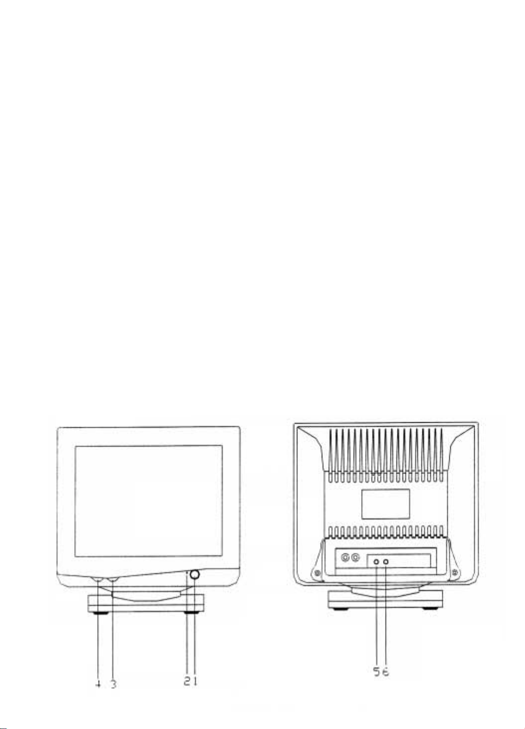
2 OPERATING INSTRUCTIONS
2-1 POWER SWITCH
Power on/off switch is a push button. To turn on the power of the unit,
press this switch. To turn off the unit, press it again.
2-2 POWER-ON INDICATOR
The power-on indicator is lit when the power is turned on.
2-3 BRIGHTNESS CONTROL
Turn the brightness control clock-wise to increase the brightness and
counter clock-wise to decrease it.
2-4 CONTRAST CONTROL
Turn the contrast control clock-wise to increase the contrast and counter
clock-wise to decrease it.
2-5 HORIZONTAL PHASE CONTROL
Turn the control clock-wise to adjust the screen to the left and counter
clock-wise to adjust the screen to the right.
2-6 VERTICAL SIZE CONTROL
To adjust vertical size for all modes: turn the control clock-wise or
counter clock-wise until a suitable height is achieved.
Page 5

3 IMPORTANT SAFEGUARDS
For your own safety read all instructions and retain them for further
reference.
3-1 POWER PL UG
This display monitor is equipped with a 3-wire grounding type power
plug. The third pin provides a safety ground for the display frame and
will only fit into the power outlet of compatible configuration.
Contact your technician to replace an obsolete outlet. Do not defeat the
safety purpose of the grounding plug.
3-2 POWER INPUT
This display should be operated only from the types of power source
indicated on the label. If there is any question about the type of power
supplied to the outlet consult your technician or dealer.
3-3 VENTILATION
Openings on the cabinet back and bottom are provided for ventilation.
To insure reliable operation and to protect the display from overheating
these openings must not be blocked or covered. Do not place the display
near or over a radiator or heating vent. If this unit is installed within
another enclosure be sure that adequate ventilation has been provided.
Never push objects of any kind through the cabinet openings as they may
come into contact with dangerous voltage points or cause short circuits
that could result in fire or electrical shock.
3-4 ATTACHMENTS
Signal sources must be of approved types and properly grounded. If
safety standards are to be maintained a service technician should perform
routine safety tests to determine that all the equipment are in safe
operating condition.
Overloaded or poorly grounded AC power systems can cause severe
difference in ground potential between the display and the signal source.
This is the case particularly on long video lines where the display and the
source are plugged into different AC power circuits. Besides causing
signal instability, ground potential may be great enough to present a
shock hazard. Ground potential tests should be part of routine safety
check carried out by a service technician.
Page 6

3-5 INSTALLATION
Do not place the display on an unstable cart, stand or shelf where it may
fall and injure personnel or cause damage to the equipm ent. Install the
unit on a solid firm base whenever possible.
Route the power cord and all cables so they will not be walked on or
tripped over. Do not allow anything to rest on the power cord.
Do not install this display in wet areas or wherever it may be exposed to
rain or water. Do not spill liquid of any kind on the unit.
3-6 CLEANING
Unplug the power cord from the outlet before cleaning the display . Use
only a damp cloth and mild detergent.
Do not use strong liquid cleaner or aerosol sprays. Do not attempt to
clean the interior of the unit; this action must be performed by the service
technician as required during normal maintenance.
3-7 SERVICING
Removal of the back by an unauthorised person may expose the user to
dangerous voltage or other hazards.
Refer all servicing to qualified service personnel. Unplug the display
from the power outlet and notify the service technician.
(a) If liquid has been spilt into the display.
(b) If the display has been exposed to rain or water.
(c) If the display has been dropped or the cabinet damaged.
(d) If fuse continue to blow.
(e) If the power cord is damaged or frayed.
(f) If a distinct change from normal operation is apparent.
Page 7

4 ADJUSTMENT PROCEDURE
This alignment procedure is for adjusting/testing picture perform ance. In
order to obtain the optimum result, the following adjustment sequence
must be followed step by step:
4-1 Check B+ voltage
(a) Test pattern: cross hatch
(b) Set up external brightness and contrast VR to central position
(c) Make sure 30Vdc = 0.1 Vdc use digital multimeter positive lead
test D913 negative point, negative lead to ground.
4-2 Vertical linearity adjustment:
(a) Test pattern: cross hatch
(b) Set up external brightness and contrast VR to central position
(c) Adjust VR300 to make equal distance between top-centre and
bottom-centre.
4-3 Horizontal-hold adjustment:
(a) Test pattern: cross hatch
(b) Set up external brightness and contrast VR to central position
(c) Turn off horizontal-sync (pin to ground)
(d) Adjust VR400 to make pattern upright.
4-4 Geom etric distortion pattern adjustment:
(a) Test pattern: cross hatch
(b) Set up external brightness and control VR to central position
(c) Adjust eight magnets on the deflection yoke make picture to the
best condition.
4-5 Video Centering adjustment
(a) Test pattern: cross hatch
(b) The video is centered by rotating the two small ma gnetic rings at
the rear of the yoke.
4-6 Horizontal-width adjustment
(a) Test pattern: cross hatch
(b) Set up external brightness and contrast VR to central position
(c) Adjust L401 to make picture width within 228 + 4 mm.
4-7 Vertical height adjustment:
(a) Test pattern: cross hatch
(b) Set up external brightness and contrast VT to central position
(c) Adjust VR301 to make height to 170 = 4 mm.
Page 8

4-8 Vertical hold (Free-run 52Hz) adjustment:
(a) Disconnect video signal
(b) Use frequency counter O lead, measure vertical yoke point,
adjustment VR302 make frequency value to 52Hz.
4-9 Raster adjustment:
(a) Disconnect video signal
(b) Set up external brightness VR to maximum , external contrast VR
to maximum
(c) Adjust VR403 have luminance equal to over 55FL
4-10 Brightness check:
(a) Test pattern: full white
(b) Set up external brightness and contrast VR to maximum position
(c) Over 55FL
4-11 Focus adjustment:
(a) Test pattern: “H” character pattern
(b) Set up external brightness and contrast VR to central position
(c) Adjust VR402 have central picture and 4 corners to be
distinguished.
Page 9
Page 10

Page 11

Page 12

Page 13

Page 14

Page 15

Page 16

Page 17

Page 18

Page 19

Page 20

Page 21

Page 22

Page 23

Page 24

Page 25

Page 26

10 PARTS LIST
PCB
LOCATION P/N
PCB 010-3001-011
RESISTOR
LOCATION P/N LOCATION P/N LOCATION P/N
R100 47R 011-0470-227 R221 62R 011-0620-227 R420 47K 011-0473-227
R101 47R 011-0470-227 R222 6K8 011-0682-227 R421 1K 011-0102-227
R102 330R 011-0331-227 R223 1K 001-0102-227 R422 013-0393-221
R103 330R 011-0331-227 R224 2K2 011-0222-227 R423 1K 011-0102-227
R104 75R 011-0750-227 R225 820R 013-0821-222 R424 1K 011-0102-227
R105 75R 011-0750-227 R226 011-0120-327 R425 013-0392-121
R106 47R 011-0470-227 R227 2K2 011-0222-227 R426 330R 011-0331-227
R107 68K 011-0683-227 R228 1K 011-0102-227 R427 1K 011-0102-227
R108 360K 012-3603-207 R229 100K 013-0104-726 R901 470K 011-0474-327
R109 1K 011-0102-227 R300 22K 011-0223-227 R902 3R9 3W 015-0397-122
R110 30K 011-0303-227 R301 011-0433-227 R903 1R 1W 014-0107-221
R111 47R 011-0470-227 R302 1R 013-0107-121 R904 1M3 011-0135-327
R112 72K 012-7202-207 R304 150K 011-0154-227 R905 1M3 011-0135-327
R113 22K 011-0223-227 R305 82K 011-0823-227 R906 47K 5W 015-0473-222
R114 22K 011-0223-227 R306 18K 011-0183-227 R907 10K 5W 015-0103-222
R115 62K 011-0623-227 R307 82K 011-0823-227 R908 3K 013-0302-222
R116 39K 011-0393-227 R308 3K3 011-0332-227 R909 68R 2W 013-0680-221
R118 78K 011-0783-227 R309 4K7 011-0472-227 R910 10R 011-0100-227
R119 75K 011-0753-227 R310 2K7 011-0272-227 R91133R 011-0330-227
R121150R 1W 013-0151-121 R311 3R3 011-0337-227 R912 10R 011-0100-227
R122 1K 011-0102-227 R312 300K 011-0304-227 R913 1R 2W 013-0107-222
R200 75R 011-0750-227 R313 1R5 011-0157-327 R914 27R 012-2707-207
R201 150R 011-0151-227 R400 1K 011-0102-227 R915 33R 012-3307-207
R202 75R 011-0750-227 R401 1K 011-0102-227 R916 2K 011-0202-227
R203 75R 011-0750-227 R402 100K 011-0104-227 R917 4KT 011-0472-227
R204 75R 011-0750-227 R403 1K8 011-0182-227 R918 10K 011-0103-227
R205 270R 011-0271-227 R404 1K2 011-0122-227 R919 1K 011-0102-227
R206 47R 011-0470-227 R405 12K 011-0123-227 R920 5M6 011-0565-227
R207 4K7 011-0472-227 R406 15K 011-0153-227 R921 10R 011-0100-227
R208 430R 011-0821-227 R407 120K 011-0124-227 R923 47R 011-0470-227
R209 470R 011-0471-227 R408 180R 013-0181-121 R924 8K2 012-8201-207
R210 91R 011-0910-227 R409 18K 011-0183-227 R925 560R 011-0561-227
R211 100R 011-0101-227 R410 820R 011-0821-227 R926 91R 011-0910-227
R212 390R 011-0391-227 R411 20R 013-0200-221 R927 5K6 011-0562-227
R213 270R 011-0271-327 R412 82R 011-0820-227 R928 011-0511-227
R214 33K 011-0333-227 R413 15K 011-0153-327 R929 1K 011-0102-227
R215 330R 011-0331-227 R414 680R 011-0681-327 R930 1K 011-0102-227
R216 47R 011-0470-227 R415 390R 011-0391-327 R931 470R 011-0471-227
R217 68R 011-0680-227 R416 82K 011-0823-227 R932 2K6 012-2601-207
R218 82K 011-0823-227 R417 130K 011-0134-227 R933 30K 012-3002-207
R219 15K 011-0153-227 R418 1R 013-0107-121 R936 1K 011-0102-227
R220 47R 011-0470-227 R419 1M2 011-0125-227
EFFECT X-RAY MARK
Page 27

CAPACITOR
LOCATION P/N LOCATION P/N LOCATION P/N
C100 47uf 050-4702-251 C309 .1 053-1045-500 C901 .22 070-2246-888
C101 .47uf 050-4792-501 C310 .1 053-1045-500 C903 4n7 071-4727-903
C102 100uf 050-1012-161 C311 47uf 050-4702-251 C904 4n7 071-4727-903
C103 10uf 050-1002-251 C312 .1 053-1045-500 C905 4n7 071-4727-903
C104 .1 053-1045-500 C313 050-2222-105 C906 071-4727-903
C105 .1 053-1045-500 C400 100uf 050-1012-161 C907 150uf 050-1512-905
C106 .001 057-1022-840 C401 .0033 053-3325-500 C908 220uf 048-2212-252
C107.001 053-1025-500 C402 .1 053-1045-500 C909 .01 051-1037-553
C108 1uf 051-1048-170 C403 68pf 052-6805-110 C910 .01 055-1035-933
C200 100uf 050-1012-161 C404 .0047 053-4725-500 C911 470pf 051-4716-814
C201 100uf 050-1012-161 C405 1uf 050-1082-501 C912 2200pf 053-2225-500
C202 270pf 051-2713-110 C406 .0018 056-1825-500 C913 390pf 051-3916-110
C203 100uf 050-1012-161 C407 .1uf 053-1045-500 C914 1000pf 051-1026-110
C204 4.7uf 050-4782-501 C408 100uf 050-1012-161 C915 .1 055-1045-840
C206 10uf 050-1002-841 C409 .001 053-1025-500 C917 .01 055-1035-840
C207 103pf 051-1037-553 C410 .0068 056-6825-883 C918 .01 053-1035-500
C208 103pf 051-1037-553 C411 560pf 051-5616-310 C919 470uf 059-4712-101
C209 100uf 050-1012-161 C412 560pf 051-5616-310 C920 470uf 059-4712-353
C300 050-4712-161 C413 1.8uf 055-1855-889 C921220uf 059-2212-101
C301 .1uf 053-1045-500 C414 .012 056-1235-935 C922 220uf 059-2212-353
C302 220uf 050-2212-161 C415 330uf 050-3312-505 C923 1000uf 059-1022-163
C303 100pf 051-1016-110 C416 .01 051-1037-553 C924 470uf 059-4712-163
C304 051-6816-110 C417 103pf 051-1037-553 C925 .22 055-2245-500
C305 .0018 053-1825-500 C418 1uf 050-1082-861 C926 331p 051-3316-110
C306 .033 053-3335-500 C419 47uf 050-4702-845 C927 .1 055-1045-840
C307 .1 053-1045-500 C420 10uf 050-1002-865 C928 102p 051-1026-410
C308 .15 053-1545-500 C421 390pf 051-3916-110 C929 102p 051-1026-410
IC
LOCATION P/N LOCATION P/N LOCATION P/N
IC100 74LS86 111-1008-007 IC300 TDA8172 112-9003-026 IC902 TL431 113-0102-005
IC101 74LS123 111-1002-011 IC400 MC1391 112-8002-015 IC903 4N35 112-1521-001
IC102 74LS138 111-1002-012 IC901 UC3842 112-5002-023
TRANSISTOR
LOCATION P/N LOCATION P/N LOCATION P/N
Q100 2SC945 114-0215-046 Q204 2N3904 114-0502-001 Q403 C945 114-0215-046
Q101 C945 114-0215-046 Q205 2SD1609 114-0308-049 Q404 C945 114-0215-046
Q200 2N3904 114-0502-001 Q400 D667 114-0308-052 Q405 2SB857 114-0108-015
Q201 2SA1145 114-0009-003 Q401 C4106 114-0210-034 Q901 114-0210-028
Q202 C945 114-0215-046 Q402 C945 114-0215-046 Q902 A966Y 114-0009-008
Q203 C945 114-0215-046
VR RES
LOCATION P/N LOCATION P/N LOCATION P/N
VR200 500R 130-1501-502 VR302 100K 131-1042-012 VR402 2M 131-2050-604
VR300 100K 131-1042-012 VR400 5K 131-5022-012 VR403 500K 131-5042-012
VR301 100K 130-4501-524 VR401 1K 130-2001-524 VR404 100K 130-4501-502
Page 28

DIODE
LOCATION P/N LOCATION P/N LOCATION P/N
D100 IN4148 117-0117-005 D203 IN4148 117-0117-005 D904 IN4007 119-1023-010
D101 IN4148 117-0117-005 D204 IN4148 117-0117-005 D905 BA159 119-1024-013
D102 IN4148 117-0117-005 D205 IN4148 117-0117-005 D906 PS104R 119-1023-018
D103 IN4148 117-0117-005 D300 IN4003 119-1023-009 D907 PS104R 119-1023-018
D104 IN4148 117-0117-005 D401 15QF6 119-1520-008 D908 IN4003 119-1023-009
D105 IN4148 117-0117-005 D402 BYT52M 119-1005-014 D909 IN4003 119-1023-009
D106 IN4148 117-0117-005 D403 PS154R 119-1523-020 D910 IN4606 117-0117-005
D107 IN4148 117-0117-005 D404 PS154R 119-1523-020 D911 PS156R 119-1523-021
D109 IN4148 117-0117-005 D405 PS104R 119-1023-018 D912 30DF2 119-3020-012
D110 IN4148 117-0117-005 D406 PS104R 119-1023-018 D913 30DF2 119-3020-012
D112 HZ5C1 118-0508-004 D407 IN4007 119-1023-010 D914 30DF2 119-3020-012
D200 IN4148 117-0117-005 D901 IN4007 119-1023-010 D915 IN4606 117-0117-002
D201 IN4148 117-0117-005 D902 IN4007 119-1023-010 ZD901 118-0508-002
D202 117-0117-005 D903 119-1023-010
BASE
LOCATION P/N LOCATION P/N LOCATION P/N
B2 232-0306-010 CRT GND 232-0123-001 L 232-0123-001
B3 232-0606-013 G 232-0123-001 LED 232-0206-005
B4 232-0415-004 G2 232-0123-001 N 232-0123-001
CRT GND 232-0123-001
WIRE
LOCATION P/N LOCATION P/N LOCATION P/N
420-0224-230 420-0504-250 420-1064-200
420-0254-255 420-0514-250 423-4100-310
420-0264-255 420-0534-245 423-6280-270
420-0408-145 420-1014-205 424-0513-300
420-0499-090
TRANSFORMER
LOCATION P/N LOCATION P/N LOCATION P/N
T400 503-2013-001 T402 503-4023-001 T902 538-0408-401
T401 503-3021-001 T901 503-1023-201
COIL
LOCATION P/N LOCATION P/N LOCATION P/N
L400 537-2007-235 L402 537-6587-145 L902 537-1087-235
L401 538-1000-101 L901 537-3306-226 L905 537-2007-235
OTHER
LOCATION P/N LOCATION P/N LOCATION P/N
S901 261-0521-401 SP203 391-0102-001 F901 521-2085-641
381-2000-001 SP204 391-0102-001 604-0003-301
SP201 391-0102-001 SP202 391-0201-002
Page 29

OTHER
LOCATION P/N LOCATION P/N
AC SOCKET ASSY 891-0030-001 USER MANUAL 312-0001-003
LED ASSY 891-0040-002 POWER CORD 400-0701-180
BASE ASSY 891-0050-002 SIGNAL CABLE 410-0101-150
CRT 500-5010-103 CARTON 305-1233-001
POLYFORM 460-0001-033 PE BAG 470-0010-001
P E BAG 470-0011-003
 Loading...