

Page 1
32” LCD-TV
Service Manual
N
N
T
T
V
V
V
V
V
V
S
S
3
3
3
3
C
C
2
3
2
2
2
2
3
2
S
S
F
F
F
F
F
F
ysstt
y
L
B
L
B
C
B
C
M
B
M
B
B
B
B
B
B
e
e
B
B
m
m
Version 1.0
April 12,2005
Page 2

Table of Contents
1. Safety and Precautions ……………………………………………1
2. Specifications.............................................…………………………3
3. Connection & Applications……….............................................….5
4. Controls Location …..................................................……….…….7
5. Remote Control.......................................................………………..8
6. Disassembly Instructions.....................……………….……….…..10
7. Block Diagram........................……………………………………..14
8. Troubleshooting…………...............................…………………….15
9. Factory Mode Setting ……………………………………………..20
10. Electronic Circuit Description...........…………………..…………21
11. Circuit Diagram.............................…………………………..…….24
12. PCB Layout.............................………………………………..……45
13. Electrical Spare Parts List …..........................……………………49
14. Mechanical Disassembly ...…......................……….…………….51
15. Mechanical Spare Parts List….........................................…………52
16. Firmware Update Procedure …………………………………….. 53
Page 3
1. Safety and Precautions
1.1 Safety Precautions :
1) Cleaning : Unplug the power cord from the AC outlet before cleaning the product.
Use a damp cloth to clean the product. Do not use liquid cleaners or aerosol
cleaners.
2) Heat sources : Keep the product away from heat sources such as radiators,
heaters, stoves and other heat-generating products (including amplifiers).
3) For added protection for this television equipment during a lightning storm, or
when it is left unattended and unused for long periods of time, unplug it from the
wall outlet and disconnect the antenna. This will prevent damage to the
equipment due to lightning and power-line surges.
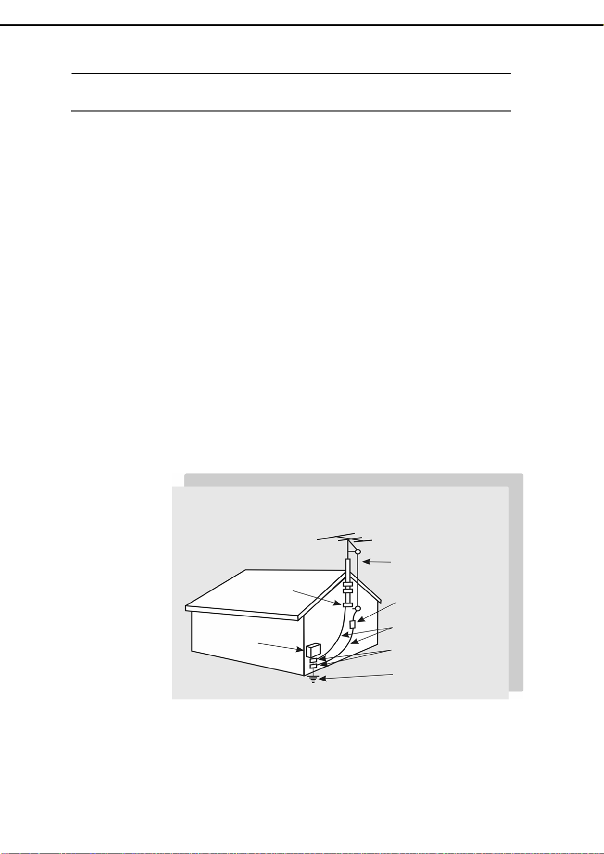
4) If an outside antenna is connected to the television equipment, be sure the
antenna system is grounded so as to provide some protection against voltage
surges.
Example of antenna grounding
As per national electrical code
Antenna lead in wire
Ground clamp
Antenna discharge
unit
Electric service
equipment
Power service
grounding
Electrode system unit
- 1 -
Page 4

5) An outside antenna system should not be located in the vicinity of overhead
power lines or other electric light or power circuits, or where it can fall into such
power lines or circuits. When installing an outside antenna system, extreme care
should be taken to keep from touching such power lines or circuits as contact
with them might be fatal.
6) Ventilation : The vents and other openings in the cabinet are designed for
ventilation. Do not cover or block these vents and openings since insufficient
ventilation can cause overheating and/or shorten the life of the product. Do not
place the product on a bed, sofa, rug or other similar surface, since they can
block ventilation opening. This product is not designed for built-in installation. Do
not place the product in an enclosed place such as a bookcase or rack, unless
proper ventilation is provided or the manufacturer's instructions are followed.
1.2 Product Safety Notice :
1) Many electrical and mechanical parts in this chassis provide special visual
safety protection. The protection afforded by them cannot necessarily be
obtained by using replacement components rated for higher voltage, wattage,
etc.
2) Before replacing any of these components, read the parts list manual carefully.
The use of substitute replacement parts, which do not have the same safety
characteristics, as specified in the parts list may create shock, fire or other
hazards.
1.3 Service Notes :
1) When replacing parts or circuit boards, wrap the wires around terminals before
soldering.
2) Keep wires away from high temperature components.
3) Keep cable and their shielding in their original position so as to reduce
interference.
- 2 -
Page 5
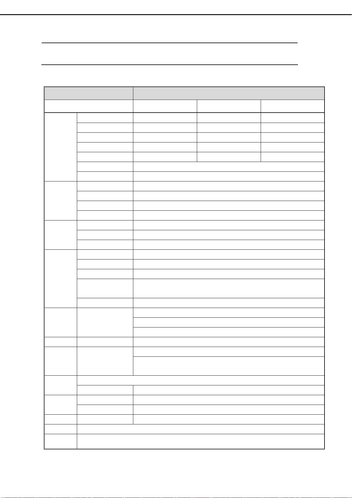
2.1 Specification :
ITEMS SPECIFICATION
Model Name V32FLBB V32FCBB V32FMBB
Screen size/ Supplier 31.51” / LG panel 31.51” / CPT panel 32.02”/ CMO panel
Aspect Ratio 16:9 16:9 16:9
Resolution
Display
TV I/P
Video I/P
PC I/P
Audio I/P Audio I/P:L/R
Video O/P Composite Signal TV only
Audio O/P
Functions
Power
Dimension W x H x D 964.8mm x 580.4mm x 279.8mm
Wight (net) 22.2Kg (without Accessories)
Contrast ratio 600:1 (typ.) 800:1 (typ.) 800:1 (typ.)
Brightness 500cd/m2 (typ.) 500cd/m2 (typ.) 550cd/m2 (typ.)
Viewing Angle Over 170 (Hor.)∘ / 170 (Vert.)∘
OSD Language Chinese , English, French , German , Spanish
TV standard (CCIR) NTSC
TV Turning system PLL 181 Ch.
STEREO MTS+SAP
CATV 125 CH.
Composite Signal CVBS x 2
Y, C Signal S-Video x 2
Composite Signal YPbPr x 2 (720p, 1080i HDTV Ready)
Analog I/P 15 pin D-Sub Connector
Digital I/P 24 pin DVI Connector
PnP compatibility DDC / 2B (Analog) , DVI 1.0 / HDCP 1.0 (Digital)
I/P Frequency
Recommended 1024 x 768 (60Hz)
Audio O/P:L/P
Sound level output
500 mV(rms)
PIP, PoP, 3D de-interlace, 3D comb-filter , V-Chip , C.C. Settings Other
Aspect Ratio Full → Normal → Zoom → Panoramic → Subtitle
Power Supply AC 110V ~ 240V, 50/60Hz
Power Consumption <180W
2. Specifications
1366 x 768 (WXGA) 1366 x 768 (WXGA) 1366 x 768 (WXGA)
F
:31.5KHz to 60KHz
H
F
:56Hz to 75Hz
V
Audio 1:CVBS & S-Video x 2
Audio 2:Y Pb Pr x 2
Audio 3:PC x 1
Speaker (Built-in):10W+10W (rms)
3.5mm miniature stereo phone jack
Accessories Remote Control, Batteries, AC cord , DVI-D cable (optional), user’s manual.
- 3 -
Page 6
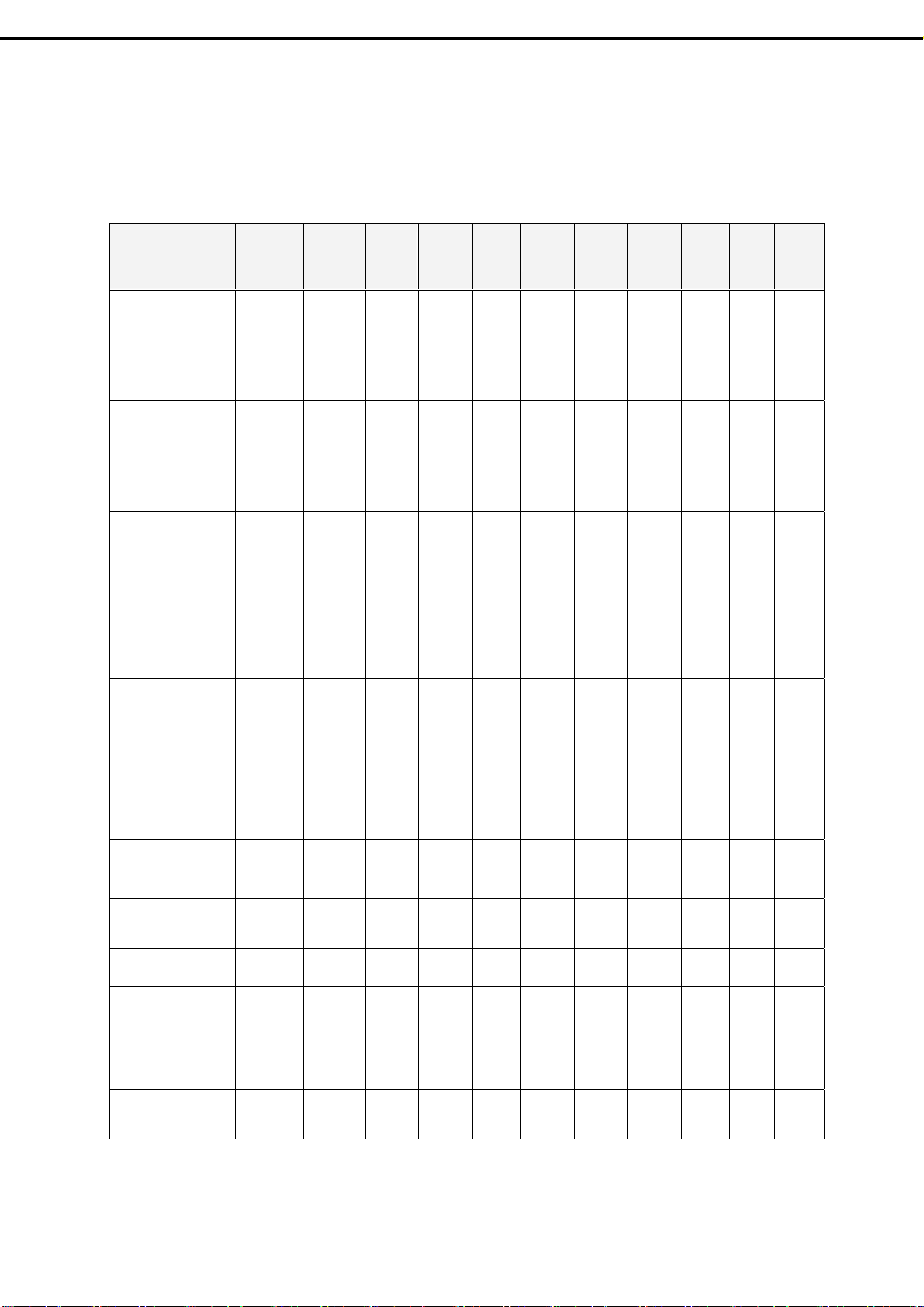
2.2 PC Input preset timing table
Mode
No.
Mode
Resolution
H.Freq
(KHZ)
V. F r e q
(Hz)
H.Polarity
V.Polarity
Pixel
CLK
(MHZ)
Hor.
Tot al
Hor.
Display
H.Back
Porch
Hor.
Sync.
Width
Ve r.
Tot al
Ve r.
Display
V.Back
Porch
Ve r.
Sync
Width
VGA 70HZ
1
VGA 60HZ
2
VGA 72HZ
3
VGA 75HZ
4
SVGA 60HZ
5
SVGA 60HZ
6
SVGA 72HZ
7
SVGA 75HZ
8
XGA 60HZ
9
640*350
640*480
640*480
640*480
800*600
800*600
800*600
800*600
1024*768
31.469
70.087
31.469
59.941
37.804
72.81
37.5
75.0
31.156
56.25
37.879
60.317
48.077
72.188
46.875
75.0
48.363
60.004
+
25.175 800 640 48 96 449 350 60 2
-
-
25.175 800 640 48 96 525 480 32 2
-
-
-
-
-
+
+
+
+
+
+
+
+
-
-
31.5 832 640 128 40 520 480 28 3
31.5 840 640 120 64 500 480 16 3
36.0 1024 800 128 72 625 600 22 2
40.0 1056 800 88 128 628 600 23 4
50.0 1040 800 64 120 666 600 23 6
49.5 1056 800 160 80 625 600 21 3
65.0 1344 1024 160 136 806 768 29 6
10
11
12
13
14
15
16
XGA 70HZ
1024*768
XGA 75HZ
1024*768
MAC VGA
640*480
MAC VGA
832*624
MAC VGA
1280*768
WXGA
1280*720
WXGA
1360*768
56.476
70.069
60.023
75.029
35.0
66.667
49.725
74.55
47.73
60
45
60
47.7
60
-
-
+
+
-
-
-
-
-
-
+
+
75.0 1328 1024 144 136 806 768 29 6
78.75 1312 1024 176 96 800 768 28 3
30.24 864 640 96 64 525 480 39 3
57.283 1152 832 224 64 667 624 39 3
80 1676 1280 198 136 795 768 23 3
74.25 1650 1280 220 40 750 720 20 5
85.5 768
- 4 -
Page 7
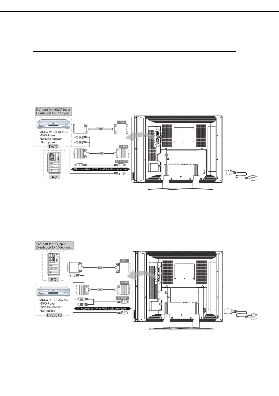
3. Connection & Applications
3.1 DVI port for HDCP Input
D-sub port for PC Input
3.2 DVI port for PC Input
D-sub port for Video Input
- 5 -
Page 8
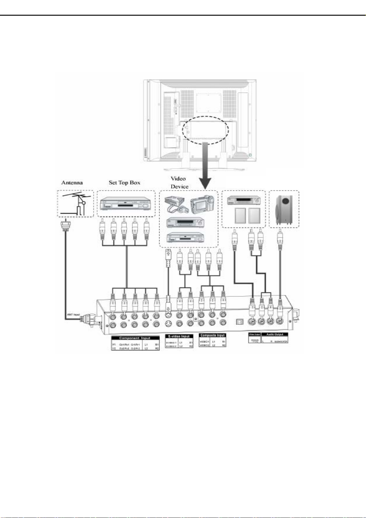
3.3 Video Expand card Connection
A/V Out
Subwoofer
Out
Audio O/P : The level of audio output cannot be changed by using the Volume, Treble,
and Bass controls on your TV. These connectors should be used with an
external amplifier that can be used to control the volume.
Video O/P : The main display must set to TV mode in order to use video out to record a
program using a VCR.
- 6 -
Page 9
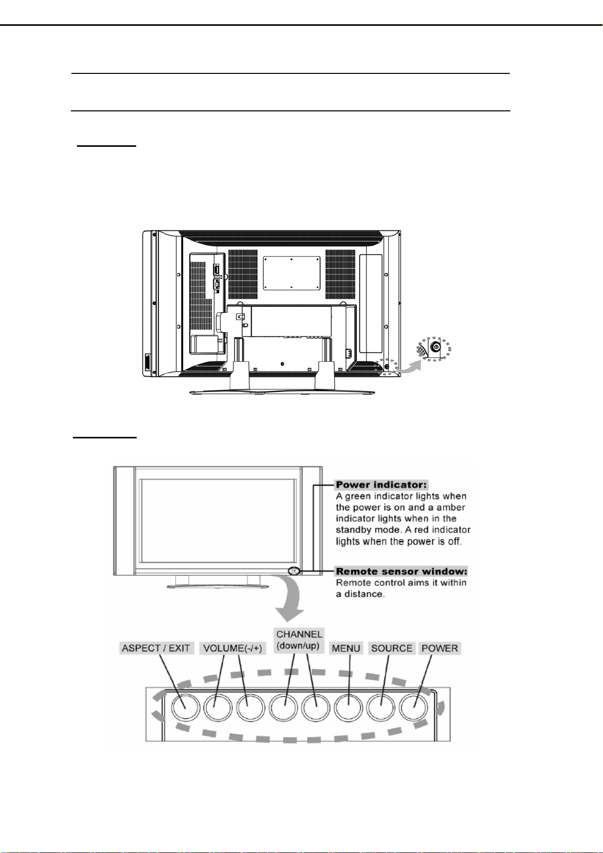
4. Control Location
Rear Side
:
Before operating the LCD-TV or remote control, users must press MAIN POWER
switch to ON. The MAIN POWER switch is located at the bottom-left back of the
LCD-TV.
Front Side :
- 7 -
Page 10
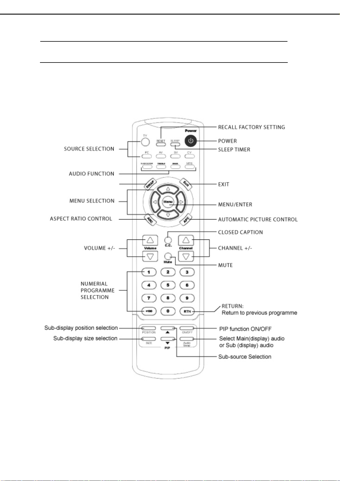
5.1 Remote Control :
VIDEO SWAP
5. Remote Control
- 8 -
Page 11
5.2 Summary of Control Button
PPoowweerr ccoonnttrrooll
POWER button Turn the TV on or off
Selecting the primary signal source
TV button Switch to TV mode
AV button Switch to AV mode (composite mode)
SV button Switch to S-Video mode
CV button Switch to CV mode (component :Y/Pb/Pr)
PC button Switch to PC mode (DVI or D-sub)
Menu Settings
MENU/ENTER button Display the on-screen menu or enter a sub-menu
EXIT/(INFORMATION) button Exit a menu or sub-menu. (Option: Display the current
channel or current primary signal source.)
UP,DOWN,LEFT,RIGHT buttons
Access to menu items
TV Changing Channels
CHANNEL△ button
CHANNEL▽ button
0~9 ; +100 button Select channels manually
RTN button Return to the previous viewed channel
Press Up to change the channel
Press Down to change the channel
Sound Control
VOLUME △ button Increase volume level
VOLUME ▽ button Decrease volume level
MUTE button Temporarily turn off audio
MTS button
TREBLE button Adjust treble level
BASS button Adjust bass level
SUBWOOFER button Enable/Disable the subwoofer
AUDIO SWAP button Exchange audio source of Main display and Sub display
Cycle through Stereo, Mono or Separate Audio Program
(SAP) multi-channel sound services
PIP Control
ON/OFF button Enable/Disable PiP viewing window
Press again to make the sub display disappear
△/▽ button
Select PiP input source: TV→AV 1 →SV1→AV 2 →SV2
SIZE button
POSITION button Move the PiP window position
AUDIO SWAP button Exchange audio source of main display and PiP window
Toggle PiP window size: 10%→20%…………90%→
100%
Other Function
SWAP button
RESET button Return to the original factory settings.
ARC button (Aspect Ratio Control) PC mode:Set the picture mode to Full, Fill aspect, One
APC button (Automatic Picture Control) Toggle screen luminosity between Normal, Clear, Dark,
SLEEP button Select a pre-set time for automatic power down.
C.C. button Enable/Disabled closed captioning.
Exchange the main and Sub display
to one.
Video mode:Toggle the picture mode between normal
→Zoom→Full→Panoramic→Subtitle.
and Theater modes.
- 9 -
Page 12
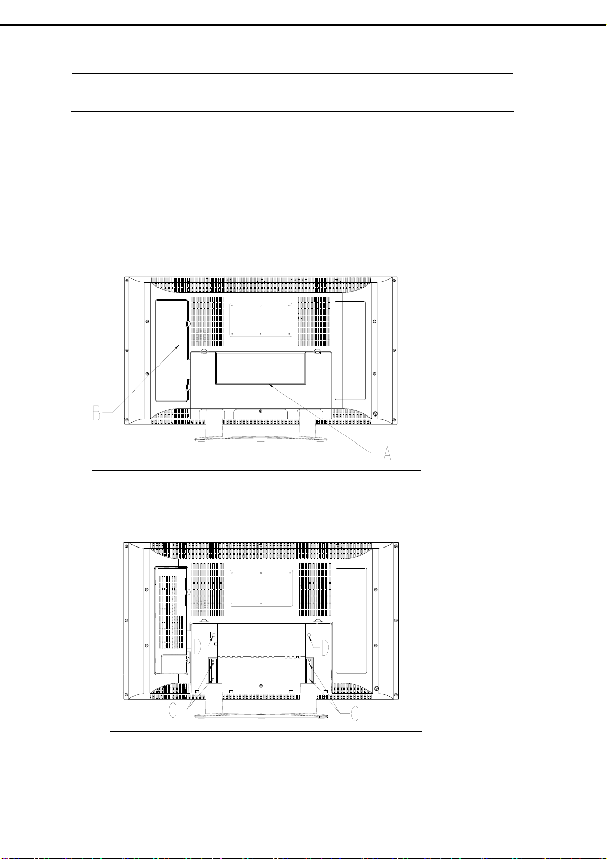
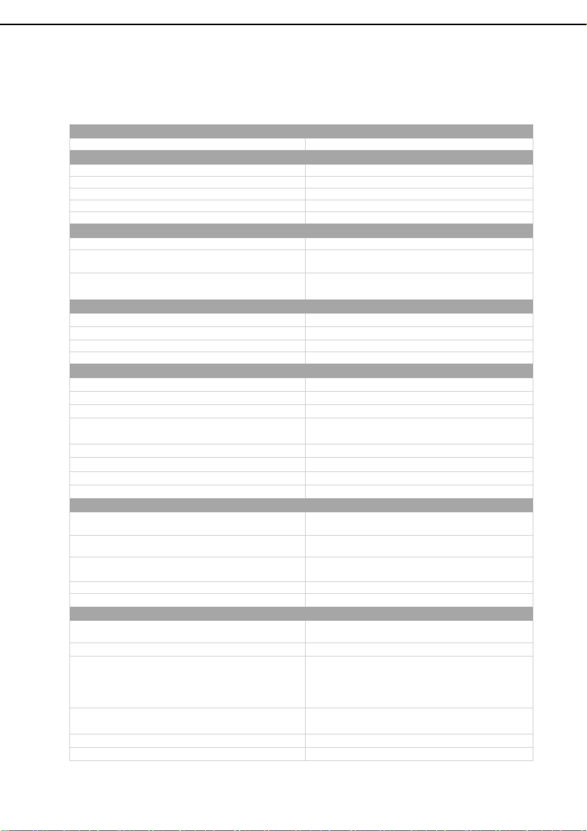
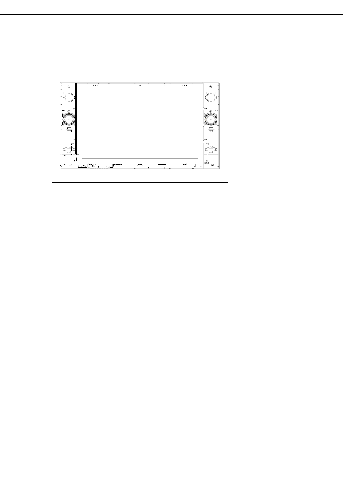
6. Disassembly Instructions
Face down the LCD-TV on a smooth plane with a soft material to protect the
panel faceplate.
A. Pull down two hooks to open the bottom cover.
B. Pull down two hooks to open the side cover.
C. Remove 4 screws and then take base assembly apart from the LCD-TV.
D. Loose 2 screws and pull up the Video Expand Card.
- 10 -
Page 13
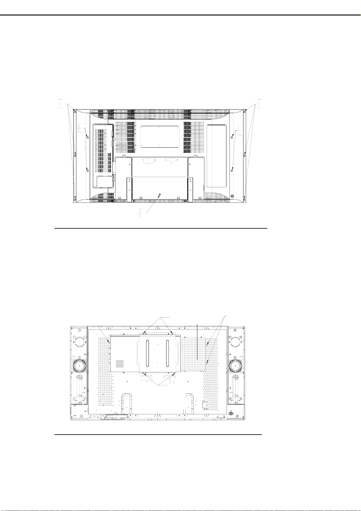
E. Remove 10 screws from the back cover.
F. Remove 1 screw from the back cover, and then take back cover apart from the LCD
TV
G. Remove 4 screws from the VESA wall-mounting bracket.
H. Remove the shield of power box.
H.’ Remove 2 screws, and then disconnect 3 wire assemblies from power box.
H.” Remove 1 screw from shield of main board, and 4 hexagonal screws from the DVI
and D-Sub connectors.
H’’
G
H
H’
G
- 11-
Page 14
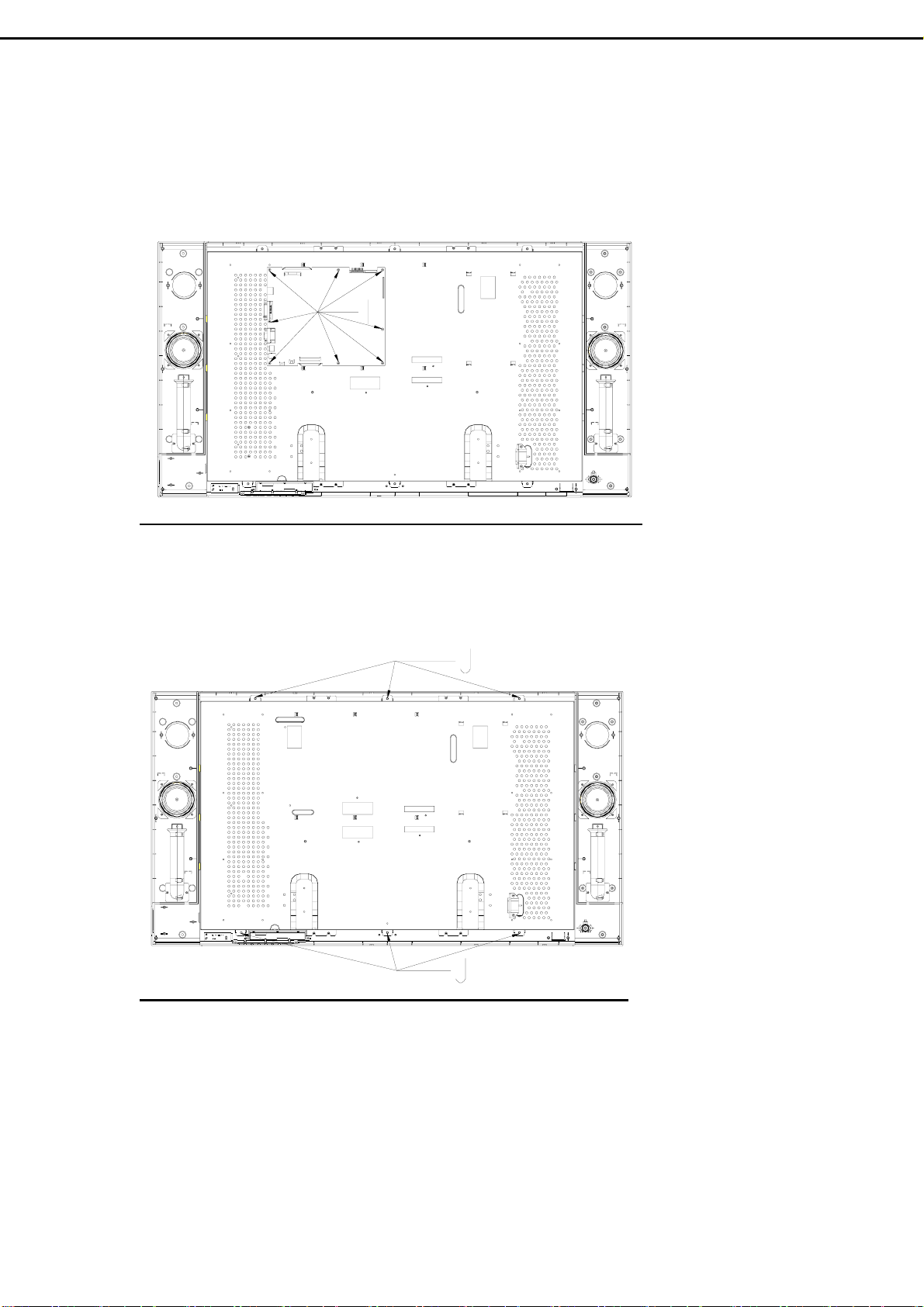
I. Remove 8 screws from the Main board, and then take Main board apart from the
Panel bracket.
J. Remove 6 screws from the Panel Bracket.
- 12-
Page 15
K. Take Panel Bracket apart from the Front Cover.
- 13 –
Page 16
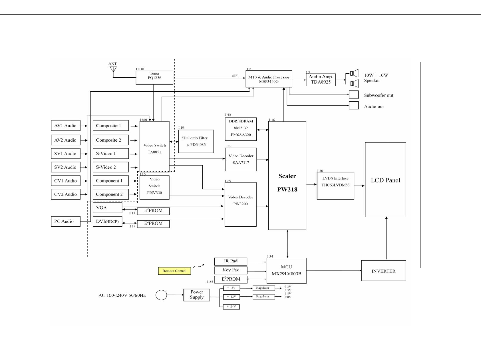
7. Block Diagram
- 14 -
Page 17
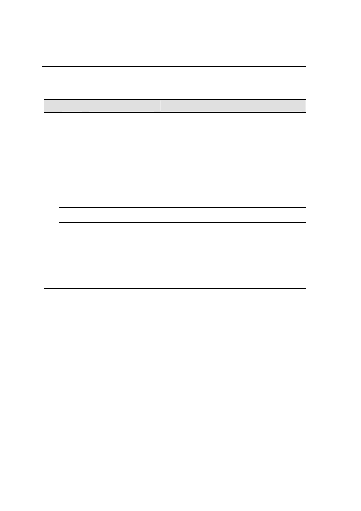
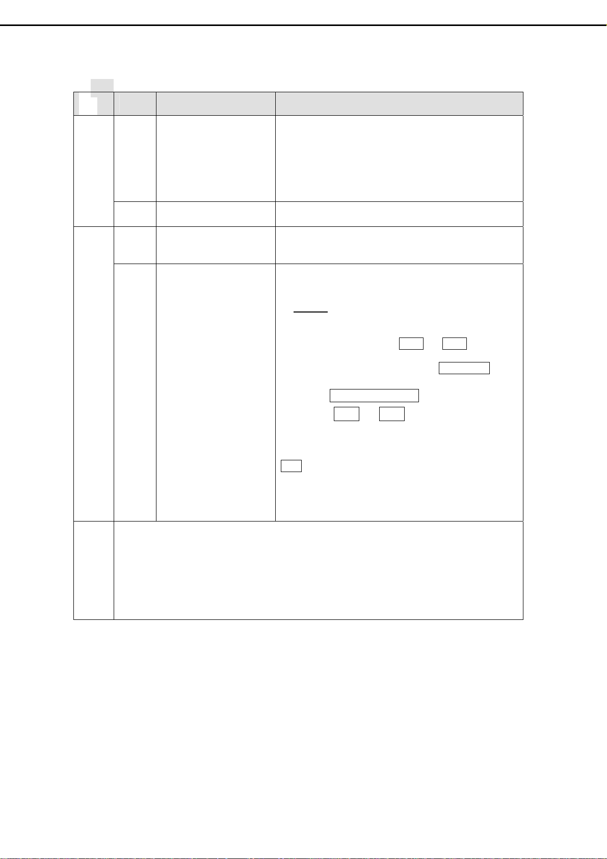
8. Troubleshooting
8.1 Symptom Codes : ( for Call Center use )
CODE SYMPTOM COUNTERMEASURES
No picture and and no Sound
Poor Picture
NP1
NP2
NP3
NP4
NP5
PP1
PP2
PP3
PP4
No Picture and No Sound
in TV mode.
No Picture and No Sound
in video mode.
TV is automatically turned
off.
Screen appears “totally
snowy” in TV mode. After
10 min., it turns off
automatically.
Screen appears “No
Signal” in video mode.
After 10 min., it turns off
automatically.
Double Images / Ghosts If the TV suffers interference from signals reflecting from
Snowy picture and noisy
Sound
Distorted picture and
noisy sound
Dotted Lines / Stripes
in the picture.
z Make sure the Power cord and Antenna cable are
properly connected .
z Make sure the batteries in remote control are not
flat.
z Press the MAIN POWER switch to ON.
z Switch to TV source by pressing TV button.
z Select the correct signal source: “ANTENNA” or
“Cable- STD/ HRC/ IRC ” in OSD menu.
z Run “Auto Search ” in OSD menu.
z Check the connection between the optional video
equipment and the TV.
z Press AV, SV, or CV button on the remote control
to select the corresponding video source.
z Check if the “SLEEP” timer is activated .
z Press POWER button to turn on the TV once again.
z Check if Aerial cable is correctly connected.
z Press POWER button to turn on the TV again.
z Press CH Up/Down buttons to change channels.
z Check if Video Cable is correctly connected and
Video Device is normal.
z Press POWER button to turn on the TV again.
z Press AV, S V, or CV button on the remote control to
select the corresponding video source.
mountains or buildings , double-pictures or Ghosts will
occur.
z Adjust the Antenna’s location and direction
z Replace it with one with better directionality.
z Turn off or disconnect the booster if it is in use , as
the booster may be inappropriate.
If snow totally blocks out the picture , there may be a
problem with the Antenna or Antenna Cable .
z Have the TV and Antenna been connected
properly ? Has the Antenna cable been damaged ?
z Is the Antenna pointing in the right direction ?
z Is the Antenna itself faulty ?
z Try using a booster , as signal transmission may be
low.
z Turn off or disconnected the booster if it is in use ,
as broadcast signals may be too strong.
If the TV or Antenna suffers interference from other
equipment , stripes or noise may appear in the picture.
z Keep the TV away from noise sources such as
personal computer , amplifier , cars, motorcycles or
hair-dryers.
z If the aerial suffers interference from a radio tower
or high-voltage wire , contact the local dealer.
-15-
Page 18
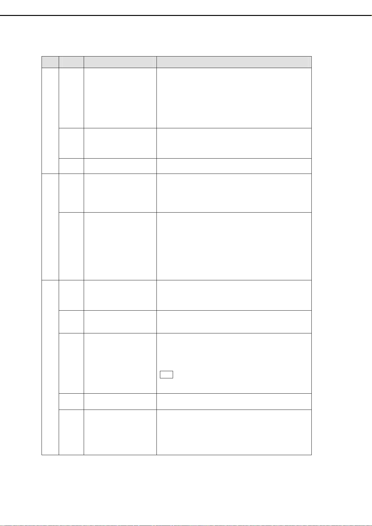
CODE SYMPTOM COUNTERMEASURES
PP5
PP6
Poor Picture
PP7
NS1
NS2 Noisy noise z Make sure that the antenna connected is 75 ohm
No Sound or Noisy Sound
PC1 PC display is Not Full
PC2 Horizontal Noise or Color
PC3 “Out of Range” message z Maximum PC resolution supported is 1360x768
PC
PC4 No Sound z Make sure PC audio Input is well connected.
Stripe noise. z Check the coaxial cable connected with the TV is not
oxidized
z Do not use 300 ohm twin lead cables as interference
may occur
z It is recommended to use a 75 ohm coaxial cable
(not supplied) to get premium quality picture.
z Keep the aerial cable away from other connecting
cables.
No color, too light or too
dark
Poor picture on particular
channel.
Good picture, no sound z Make sure the headphone is not connected. (option)
Screen
pattern is not uniform
z Adjust the picture settings —
Contrast, Saturation , Color Temp.
z Press RESET button on remote control to return all
settings to factory settings.
z Use “Fine Tune” in OSD to manually adjust a
particular channel for optimal reception.
z Check audio connections between Equipment &
LCD-TV.
z Press MUTE or VOL Up to cancel the muting.
coaxial cable (not supplied) , not 300 ohm twin lead
cables .
z Keep the antenna cable away from other connecting
cables.
z Press MTS button to select “Mono” which will
reduce the noise.
z Adjust BASS or TREBLE properly on remote
control.
z Select “Auto” in OSD menu to optimize the image .
z If executing Auto Image Adjust still can not achieve
full screen display, adjust “V. Position” and “H.
Position” in PC mode
z Select “Auto” in OSD menu to optimize the image .
z If still no good , adjust “Phase” in OSD menu
, so the screen will appear “Out of range” at higher
resolution.
z Reduce the resolution to 1360x 768 from the PC.
Note The panel resolution is 1366x768, which is not a
standard timing, so it may not suit for all PC graphic
cards.
APC, Brightness,
PC5 After “No Signal ” has
appeared on PC mode for
a while, the view
disappears and the LED
Indicator turns from
Green to”Amber” .
z Press any key on keyboard or move the mouse to
activate the PC , because the PC may go to power
saving status.
z Check if the D-sub or DVI connector (Cable) is
disconnected or loose.
-16-
Page 19
-16-
CODE SYMPTOM COUNTERMEASURES
RC1 Remote Control does not
work
RC2 Can not change channels
Remote Control
PH1
NG1
Picture Halt / Abnormal
with the remote control
Picture suddenly Stops
Responding or
abnormal.
Issues can’t be solved. z If the picture still abnormal, execute “ Clear
z Make sure the batteries in remote control are not flat
z Check the polarity of the batteries
z Use the remote control in the front of the TV or from
less than seven meters away.
z make sure the Remote Sensor Window is not under
strong lighting.
z Press TV button to switch to TV mode.
z Press RESET button on remote control .
z Unplug and then plug the Power Cord of the TV from
the AC outlet.
EEPROM”.
STEPS
1. Press POWER Button to turn on LCD-TV.
2. Use right hand to press Ch▽ and Ch△ buttons
3. When UPDATE EEPROM appears on the screen,
:
simultaneously, and keep pressing them (do not
release). Use left hand to turn the Main Power
Switch to OFF and then ON.
release Ch ▽ and Ch △ buttons, which you’re
pressing.
Note : Remind user that every setting will return to
factory preset mode including PIN of parental
control (PIN : 000000), channel setting.
1. CV and PC modes, including D-sub and DVI, are not available on Sub-display of PIP and
PoP.
2. TV mode is note available on side by side display.
Note
3. If Main-display is CV and Sub-display is ON, de-interlace function is not available for CV.
-17-
Page 20

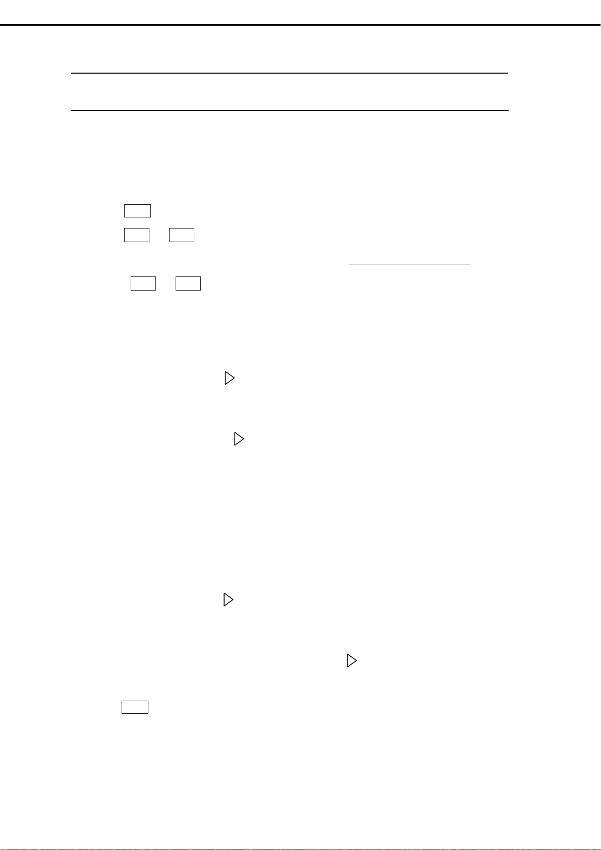
8.2 Flow Chart : ( for Repair Center use )
(
g
(1) Power fair :
No picture
Appears
No
No picture
No
picture
No
picture
No
picture
Check if sources are
connected correctly.
Is panel wire P015A
No
connected with P15
correctly?
Ye s
Is Backlight
lit?
Is connector CN3
No
(12P) on Power
Module connected
correctly?
Ye s
Ye s
No
Does the LED
light up?
Ye s
No
Does LED light
Amber?
Ye s
Is it entering screen
protection (or power
saving) on PC mode?
Restart signal to
ensure H. V. sync.
are not absent
Ye s
Picture
appear
Picture
appear
Picture
appear
Picture
appears
Replug
s
Replug
s
Clear
EEPROM
s
Replug
否
否
No
No
Replace I12
Is the Voltage at
否
I12 #8 = 5V?
Clear
EEPROM
Picture
appears
Replace
I34
Picture
appears
Replace Main
Board PWB-0713
Ye s
No picture
MCU)
No picture
0~0.5V
Check
I12 #4
No
3~5V
Picture
appears
End
Check connector CN3 (12P) and
Wire U901A : Red wire = 24V ,
Blue & White wires > 2.5V
Replace Power
Module (.PB01)
No picture
No
Picture
appears
Ye s
No
Re-plug U901A to
connector CN3
(12P) , and then
check volta
es again
Ye s
Replace Inverter.
Ye s
No picture
- 18 -
End
Check if Inverter is
connected correctly.
Ye s
No
Picture
appears
No picture
Send to
factory
for repair.
Picture
appears
Replug
No picture
Page 21

(2) Picture Abnormal:
p
N
p
Picture Abnormal
Clear EEPROM, and
then check if the
picture is normal.
Ye s
Is the panel cable
No
P015A
connected with
P15 correctly?
Replace V901
(LCD panel)
Ye s
No
and check the
Re-plug the
panel cables,
picture.
Ye s
No
Check if SMT devices
around I16 &I43 are
welded correctly.
Ye s
Re-welding,
and then check
the picture.
Change main
board PWB-0713,
Ye s
and then check
picture.
Ye s
Change Power
Module PB01, and
then check
No
Ye s
No
No
icture.
End
- 19 -
Ye s
Change
Inverter and then
check
No
icture.
o
Page 22
9. Factory Mode Setting
* The steps to enter Factory Mode are identical to the steps of firmware version check
in Chapter 16 .
9.1 Procedures to enter Factory Mode:
1) Press Power Button to turn on the LCD-TV. (Power Indicator: Green color)
2) Press Ch ▽ and Ch △ buttons simultaneously, and keep pressing them ( do not release) .
3) When the version appears at the bottom of the screen such as V32FCBB-U21-MP-1.0-0214,
release Ch ▽ and Ch △ buttons you are pressing. Now the LCD-TV is in Factory Mode.
9.2 Three options for qualified personnel adjustment in Factory Mode:
1) FACTORY RESET : Pressing button will recover Brightness, Contrast, Backlight, Sharpness,
Color, Hue, H. Position, V. Position … to preset condition. It’s function is identical to RESET button on
remote control.
2) EVALUATION : By pressing button, Evaluation/Service Menu offers qualified personnel to
adjust parameters. Please don’t adjust the parameters until the manufactory notices. If the parameters are
modified carelessly, please execute “initial EEPROM” to recover the preset parameters as Step 3 of
Chapter 16.
3) CALIBRATION : If LCD panel or main board has to be changed, the Calibration Adjustment must
be executed.
a. CV mode calibration– Connect the Pattern Generator with Color Bar pattern and resolution 480p or
720p to the YPbPr connector of the LCD-TV. Then, press CV button on remote control and execute
color calibration by pressing button under Calibration OSD.
b. PC mode calibration— Connect Pattern Generator with 32-stair gray pattern and resolution
1280x720(60Hz) or 1360x768(60Hz) to the D-sub connector of the LCD-TV. Then, press PC button
on remote control and execute color calibration by pressing button under Calibration OSD.
9.3 Exit Factory Mode :
1) Press Power Button to turn off and then on the LCD-TV to exit the Factory Mode.
- 20 -
Page 23

10. Electronic Circuit Description
10.1 Main Board (PWB-0713)
(1) Power supply:
Refer to circuit diagrams sheet 15 of PWB-0713, and Power Module (PB01)..
Power Module (PB01) provides 24V、 12V、5V to Main Board via wire P016A and connector P16
#1~2(Blue wires)、#3~4(Yellow wires)、#5~7(Red wires).
The Backlight control signal from I16#W10 (Scalar: PW218) is applied to Inverter through P16# 11
(Green wire) on Main Board, CN2#11 and CN3#2 (Blue) on Power Module.
Switching 24V、12V on or off is controlled by I16#B10 (Scalar: PW218) and applied to Power
Module (PB01) via P16# 12~13 (White wires) on Main Board, and CN2#12~13 on Power Module.
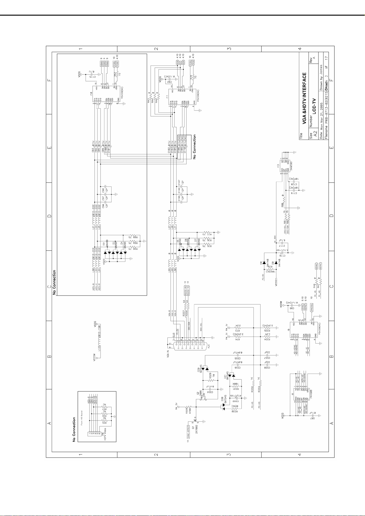
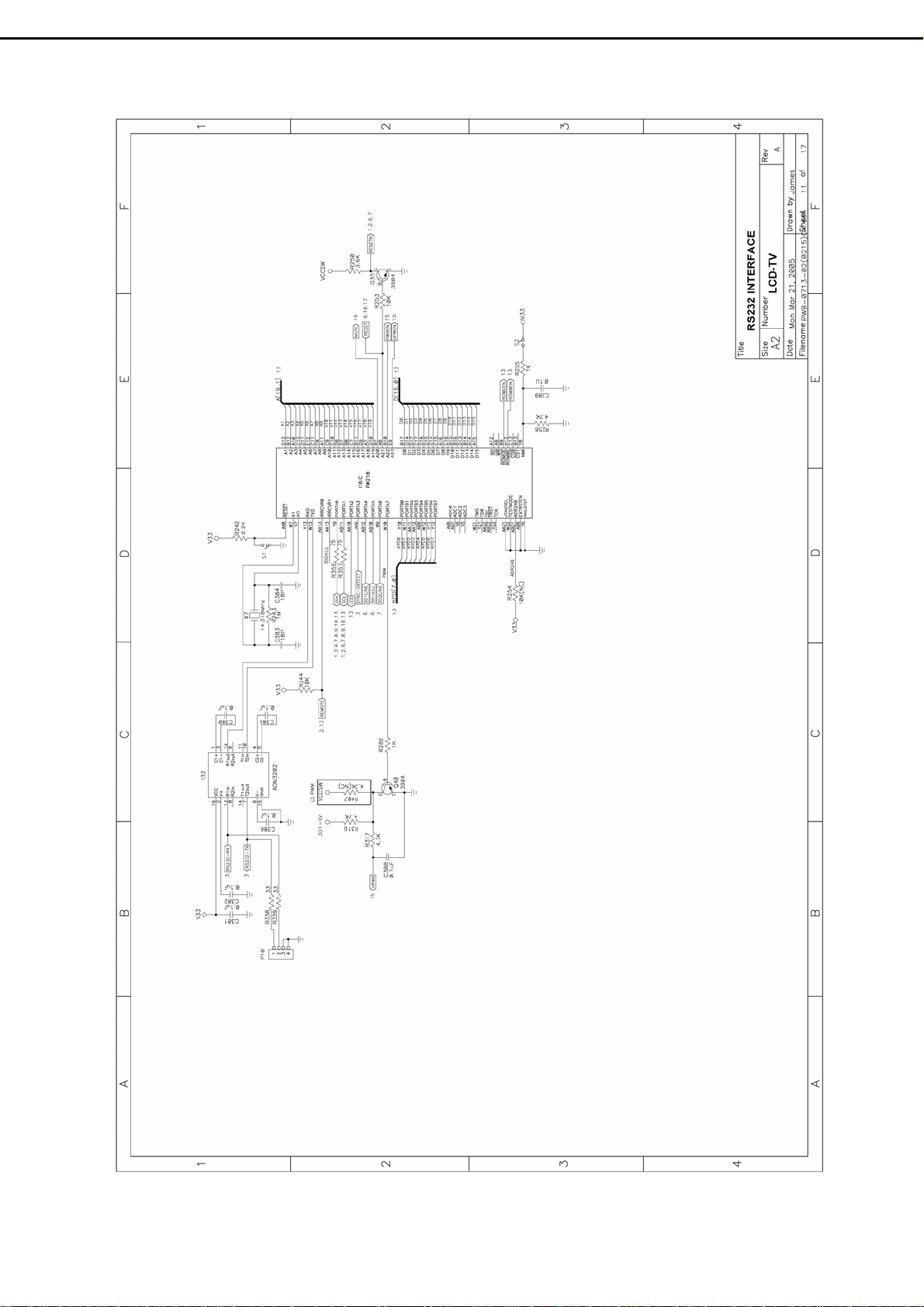
(2) D-sub Signal:
Refer to circuit diagrams sheet 3 and 10 of PWB-0713.
The analog R.G.B. video input signals are supplied through the PJ4 (15pin D-sub connector), and
these three input signals are approximately 0.7Vpp. R75、R76、R77 give resistance of 75Ω respectively
for impedance matching. These R、G、B video signals are ac coupled via 0.1uF capacitor C364、C365、
C366 and then fed into ADC port of I28 at pin 33、49、40 respectively. Then, analog R、G、B video signals
are converted to the their digital forms in I28. The outputs of digital data, including 8 bits red、8 bits
green、8 bits blue signals, are assigned at pin119 ~ 125、pin 111 ~ 118、pin 101 ~ 110 of I28,and applied
to INOR、INOG、INOB of I16 (Scalar:PW218).
H.sync.、V.sync. are applied to I28 # 79、#80 (H.Sync.、V.Sync.), and the processed signal taken from
#129、#131 are fed into I16 #J3、#J1 (INOHS INOVS).
CLK signal is taken from I28 #127 (GCLK) and applied to I16#L4 (INOCLK). The PC-Analog is
designed to have the DDC/2B functions. Communication between the LCD-TV and Computer for DDC is
via PJ4 (D-sub connector ) #15、#12 ( SCL、SDA signals) . The computer will read out the EDID from the
I13 (EEPROM) and the EDID data is written into the EEPROM in the factory during production.
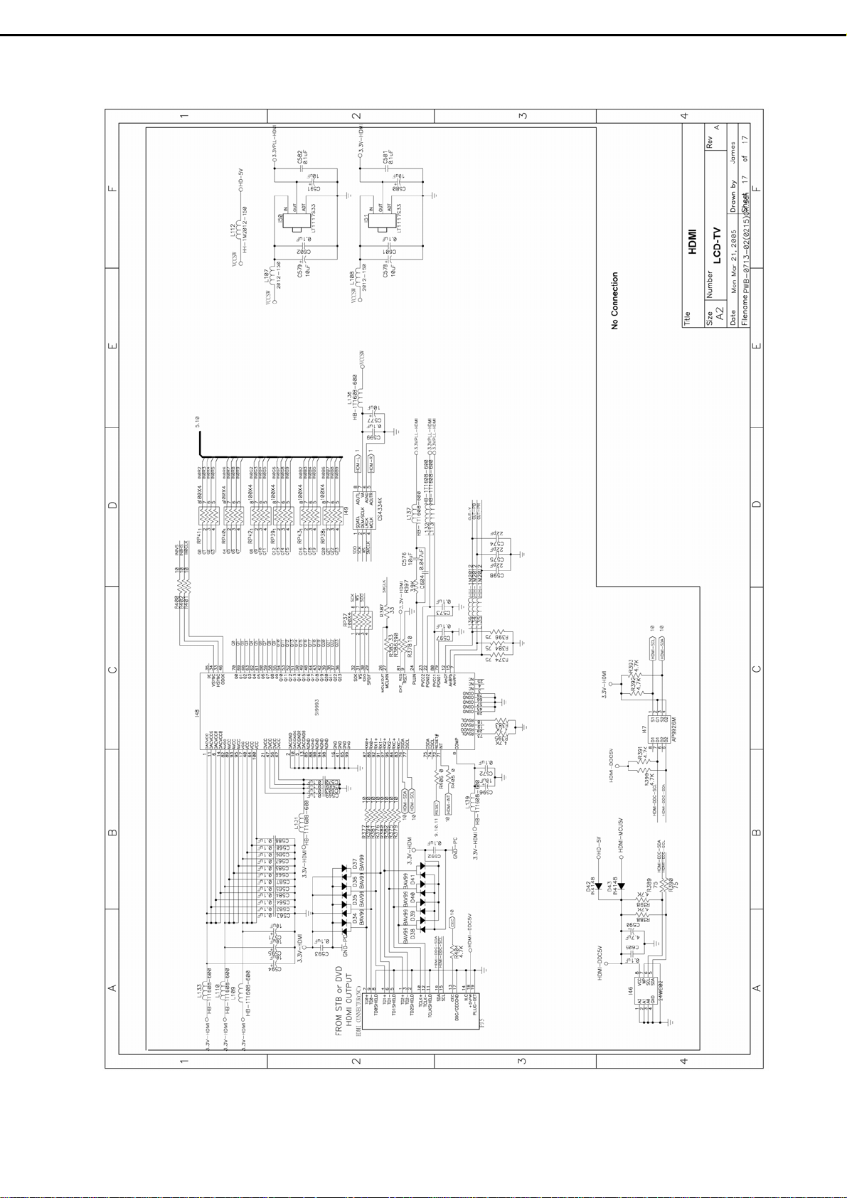
(3) DVI / HDCP Signal:
Refer to circuit diagrams sheet 5 and 10 of PWB-0713.
The TMDS (Transmission Minimized Differential Signaling ) signals are supplied through the P9 (DVI
connector ). The TMDS data pairs are assigned at #18~17(RX0)、#10~9 (RX1)、#2~1pin (RX2) and clock
pairs are assigned at #12~13(RXC), and then fed into I28(PW3200B) #9~10 (TX0)、#6~7 (TX1)、#3~4
(TX2) , #12、13 (TXC).
The I28 (PW3200B) supports High-bandwidth Digital Content Protection (HDCP) by decrypting the
pixel data stream received from an HDCP transmitter in the video host system. HDCP provides a secure
method of delivering high-definition content between a host (such as a set-up box, DVD player, or D-VHS
player) and display (such as an HDTV, projector, or A/V receiver).
The I28 PW3200B comes pre-programmed with a production set of HDCP keys in its internal
EEPROM. In this way, the keys are provided the highest level of protections as required by the HDCP
specification.
- 21 -
Page 24

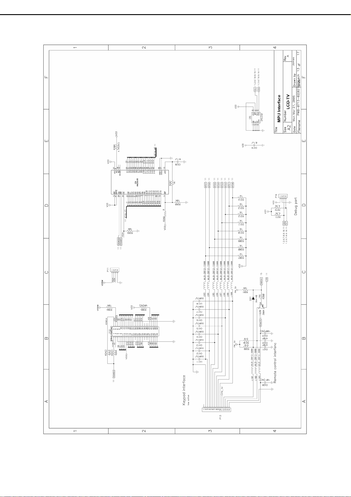
(4) MCU (Micro Controller) :
Refer to circuit diagrams sheet 13 and 11 of PWB-0713.
The microcontroller I34 (MX29LV800 or AM29LV800) is a flash type processor without extra
crystal for clock. The address signal A1~A19 of I34 (# 25~18、8~1、48、17and 16) are connected to
A1~A19 of I16 (Scalar : PW218), and data signal D0~D15 are also connect to D0~D15 of I16 (Scalar :
PW218).
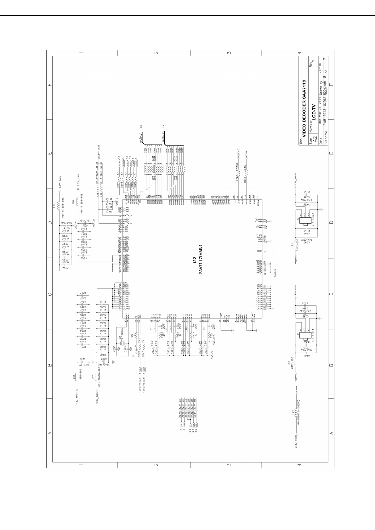
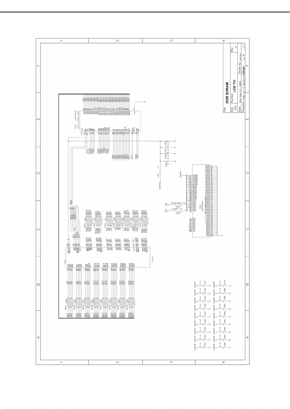
(5) Scalar :
Refer to circuit diagrams sheet 5、11、12、14 of PWB-0713.
I28 ( Video Decorder : PW3200B) is used to decode the signals of PC、Component、Composite, and
then these digital signals are applied to the ports IN0R、IN0G、IN0B of I16A (Scalar: PW218).
I22 (Video Decorder: SAA7117) is used to decode signal of Composite only, and then these digital
signals are applied to the ports IN1R、IN1G、IN1B of I16B (Scalar: PW218).
Address and Data bus A1~A19、D0~D15 transfer data between I16C (Scalar: PW218 ) and I34
(MCU). (sheet 11)
I16C #AB13 is connected with Infrared Receiver via connector P13 #15.
The ports A1BLU、 A1GRN、A1RED of I16D (Scalar: PW218) are applied to I36 (LVDS) for
Panel’s T-Con Board. (sheet 14)
(6) Panel interface :
Refer to circuit diagrams sheet 14 and 15 of PWB-0713.
The signals of panel interface are all applied from I36 (LVDS) and then fed into LCD Panel through
connector P15 and wire P015A.
Power +12V for LCD Panel is controlled by the signal DPWON
(MMTB3904).
The signals PWRON
Backlight On / Off state and Panel luminance through P16, CN2, CN3 .
The LVDS signals IN0、IN1、IN2、IN3 from I36 (LVDS) #37~38、41~42、45~46、47~48 are applied
to LCD Panel through P15 and P015A. These four pairs LVDS signals are used for panel image display.
and VPWM from I16C #B10、W10(Scalar: PW218) are used to control the
from I36#32 and Q36
10.2 Key、LED & IR Board
Refer to circuit diagrams sheet 13 of PWB-0713 and sheet 1 of PWB-0768 .
- 22 -
Page 25

10.3 Inverter Board
The Power Module provides +24V through CN3 #3~7 (Red wire) and offers 3.5A (typical) to both
Inverters on LCD panel.
The brightness adjustment in OSD menu is to control the voltage at P16#11 while this voltage is
offered by Q40, which inverts the state of I16 #w10. The range of the voltage is from 0V to 3.3V. If the
voltage of P16 #11 is 3.3V, the screen will get light; if it’s 0V, the screen will get dim. It means that the
different voltage will change the lamp current through the inverter to make the screen lighter or dimmer.
10.4 Power Module :
Refer to chapter 11.4 Power Module (PB01) pin assignment and sheet 15 of PWB-0713.
Power Module (PB01) provides 24V、 12V、5V to Main Board via wire P016A and connector P16
#1~2(Blue wires)、#3~4(Yellow wires)、#5~7(Red wires).
The Backlight control signal from I16#W10 (Scalar: PW218) is applied to Inverter through P16# 11
(Green wire) on Main Board, CN2#11 and CN3#2 (Blue) on Power Module.
Switching 24V、12V on or off is controlled by I16#B10 (Scalar: PW218) and applied to Power
Module (PB01) via P16# 12~13 (White wires) on Main Board, and CN2#12~13 on Power Module.
10.5 Video/ TV Expand Card : (Optional)
Refer to circuit diagrams sheet 1and 2 of PWB-0733.
This Video Expand Card processing video and audio signals is no need for pure monitor.
(1) Video : Different video signals, including Composite video (CVBS), S-Video, Component
Video(YPbPr), entry though this board. Composite and S-video signals are fed to I22 (Video decorder)
through I801 (video switch) to decode video format, and then fed to I16 (Scalar). Component signals
are fed into I28 (Video Decoder) through I801 (Video Switch) to decode video format, and then
connect to I16 (Scalar).
(2) TV : TV signals from antenna enter UT01#1( Tuner: FQ1236 MK3). UT01#14 outputs Audio MPX
signal, while UT01#12 outputs TV (CVBS) video signal. Audio MPX signal is applied to Audio
Processor I2 (MSP3440) to do MTS demodulation. Audio signals such as Mono, Stereo, SAP could be
output and then amplified through I3 (Audio Power Amp.) to speaker.
(3) Audio : Other audio sources are respectively connected to different left and right channels of Audio
Processor ( I2:MSP3440 ). Which audio will be output is controlled by I34 (MCU) and selected
through I2 (Audio Processor). Then, the selected audio source will be sent to speaker through I3
(Audio Power Amp:TDA8925) .
(4) Closed-caption and V-chip :
These functions are built in I16 (Scalar: PW218) and controlled by firmware.
- 23 –
Page 26

11. Circuit Diagram
11.1 Main Board (PWB-0713)
- 24 -
Page 27

- 25 -
Page 28
- 26 -
Page 29

- 27 -
Page 30

- 28 -
Page 31

- 29 -
Page 32

- 30 - - 31 -
Page 33
Page 34

- 32 -
Page 35

- 33 -
Page 36
- 34 -
Page 37
- 35 -
Page 38
- 36 -
Page 39

- 37 -
Page 40

- 38 -
Page 41

- 39 -
Page 42
- 40 -
Page 43

11.2 Tuner & I/O Board (PWB-0733) :
- 41 -
Page 44

- 42 -
Page 45
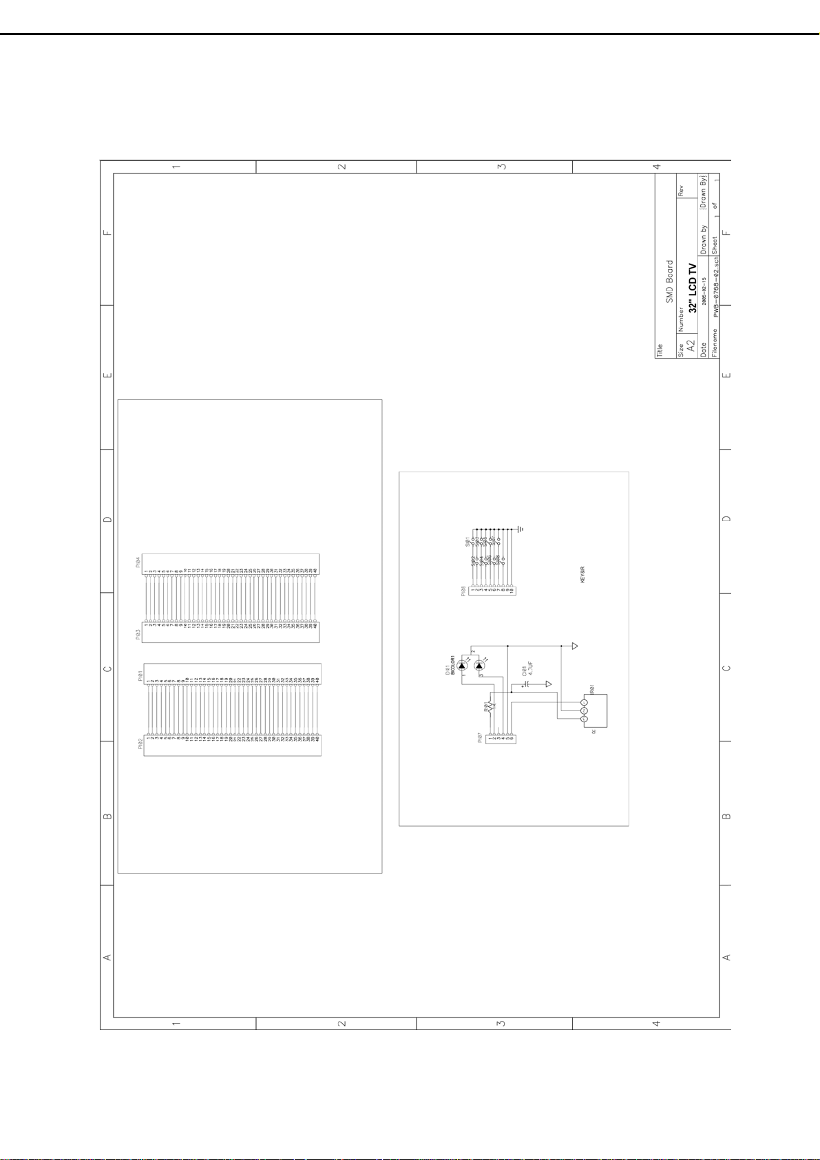
11.3 Interface、Key、IR Board (PWB-0768) :
- 43 -
Page 46
CN2
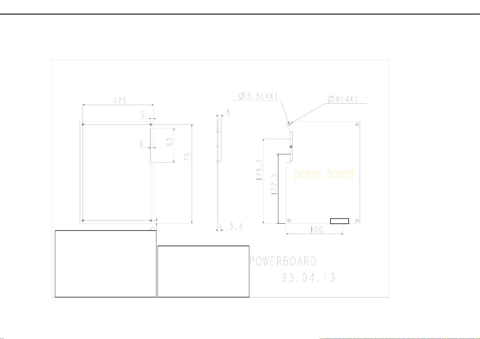
11.4 Power Module (PWB-0769) :
- 44
CN3
-
Top View
CN1
CN2 1~2 24V (Blue)
3~4 12V (Yellow)
CN3 1.Inverter ON/OFF (White)
5~7 5V (Red)
2.Backlight Control (Blue)
8~10 GND (Black)
3~7 24V (Red)
11 Backlight Control (G.)
8~12 GND (Black)
12~13. 24V、12V ON/OFF(W.)
AC IN
Page 47
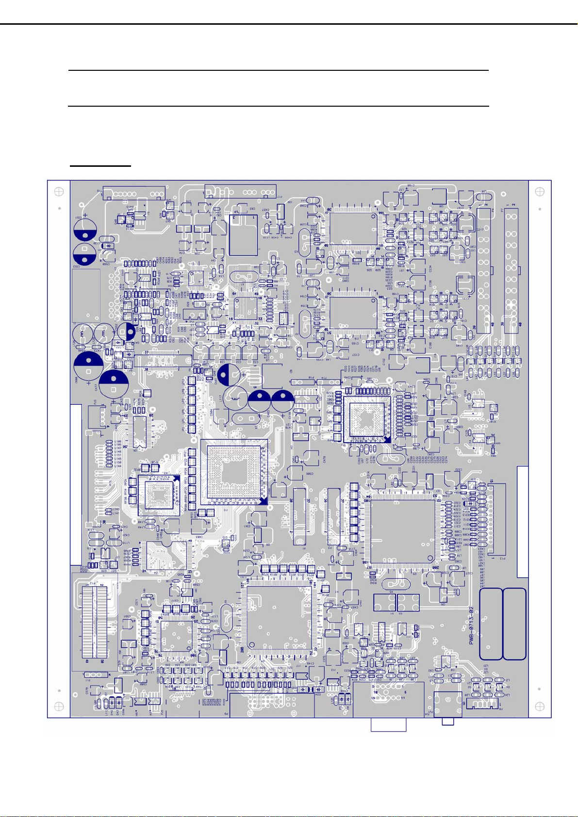
12. PCB Layout
12.1 Main PCB (PWB-0713) :
Front Side
- 45 -
Page 48

Rear side
- 46 -
Page 49
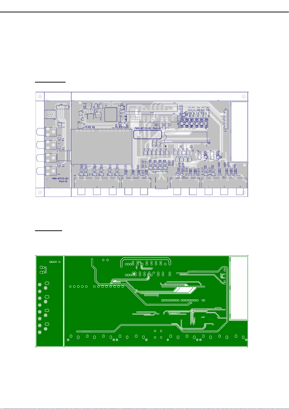
12.2 Tuner PCB & I/O PCB (PWB-0733) :
Front Side
Rear side
- 47-
Page 50

12.3 Interface、Key、IR PCB (PWB-0768) :
Front Side
Rear side
- 48 –
Page 51
13. Electrical Spare Parts List
Model Name : : V32FLBB-U21 (Set) / M21(SKD) with LG - Panel
V32FCBB-U21 (Set) / M21(SKD) with CPT-Panel
No. Name Description
1 PWB-0713 Main Board with MCU (assembly)
2 PWB-0768-K Key Board (assembly)
3 PWB-0768-I IR Board (assembly)
4 PWB-0768-C Connector Board (assembly)
5 PWB-0733-1 Tuner Board (assembly)
6 PWB-0733-2 I/O Board (assembly)
V32FLBB-U21
(5934132007)
V32FCBB-U21
(5934132003)
5097636002
5097636001 5097636001
5098800980 5095670742
5098800957 5095670742
5098800981 5097636410
5098800958
5098800982 5097636408
5098800959
5098800983 5098800975
5098800960 5098800975
5098800984 5098800976
5098800961
V32FLBB-M21
(5934132008)
V32FCBB-M21
(5934132005)
5097636002
5097636410
5097636408
5098800976
7 V901
8 P015A
9 U901A
10 PB01 Power Module (w/o power module case)
11 P013A
32" LG Panel – LC320W01-A6 5051253677 5051253677
32" CPT Panel – CLAA320WA01 5051253683 5051253683
Wire Ass'y W30P/30P Conn.
Panel ÅÆ Main board
Wire Ass'y W12P Conn.
Power ModuleÅÆ Inverter Board.
Wire Ass'y W15P / 10P & 6P Conn. :
* Main board (15pin) ÅÆ
Keyboard (10P) and IR board (6P)
- 49-
E057430005 E057430005
E057430001
5057412042 5057412042
5057414023 5057414023
6693006612 (Ra)
6693006600 (Rb)
5057415267 5057415267
E057430001
6693006612 (Ra)
6693006600 (Rb)
Page 52

V32FLBB-U21
(5934132007)
V32FLBB-M21
(5934132008)
No. Name Description
V32FCBB-U21
(5934132003)
12 P016A
13 PJ003A
14 PJ003B
15 SP01 Speaker x1 (SPk-256 : 10~15W / 4ohm) 5055125600 5055125600
16 SP02 Speaker x1 (SPk-256 : 10~15W / 4ohm) 5055125600 5055125600
17 P807A
18 P901 Power Cord 5056705900
Wire Ass'y W/13P Conn.
* Power module ÅÆ Main board
Wire Ass'y W4P / 2P Conn. :
* Main board (4P) ÅÆ
Speaker connectors (2P) R and L
Wire Ass'y W/2P Conn. :
* Speaker connector (R and L) x 2 pc’s
Wire Ass'y 10P / 6P Conn. :
* Tuner Board ÅÆ I/O Board
5057413007 5057413007
5057404397 5057404397
5057404371 5057404371
E057410002 E057410002
V32FCBB-M21
(5934132005)
5056705900
19 P106 DVI-D Cable 5057424011 5057424011
20 RT01 Remote control 5052731028 5052731028
21 Y001 User’s Manual 5030057155 5030057155
- 50-
Page 53

14. Mechanical Disassembly
- 51 -
Page 54
15. Mechanical Spare Parts List
No. Name Description Parts No.
M1
M2
M3 6F01N SPEAKER INSULATION SHEET 5646510300
M4 6F01 FRONT COVER (w/o Speaker Net) 5642298703
M5 6F06 POWER CAP 5641100500
M6 6B03 FUNCTION KEY 5642850901
M7 6F03 IR LENS 5640332100
M8 6F04 SOUND PIPE 5642680700
M9 V901N
M10 5C01
M11 5C04 MAIN PCB SHIELD 5646257000
M12 5B03 VESA BRACKET 5648743900
M13 6B02 BACK COVER (w/o Sponge & VESE Plate ) 5642298801
M14 6B04 NECK COVER 5642319801
M15 6B05 D-SUB COVER 5642320101
M16 6B08 TUNNER BOX -- UP 5642730860
6F02P SPEAKER NET-- Right 5642564951
6F02N SPEAKER NET-- Left 5642564901
6F02 SPEAKER SCREEN -- Right 5642321101
6F07 SPEAKER SCREEN -- Left 5642321151
PANEL BRACKET Æ for LG PANEL 5642736700
PANEL BRACKET Æ CPT PANEL no need Null
LCD MAIN BRACKET Æ for LG PANEL 5642730702
LCD MAIN BRACKET Æ for CPT PANEL 5642730701
M17 6B07 TUNNER BOX -- DOWN 5642730960
M18 5B02 NECK BRACKET 5648744001
M19 2B01 BASE COVER 5641415902
M20 5B01 BASE BRACKET - STEEL 5640408900
M21 5B02N RUBBER FOOT 5642025400
1 1P23 EPS BLOCK L/T V32 9523440356
2 1P24 EPS BLOCK R/T V32 9523440456
3 1P21 EPS BLOCK L/B V32 9523440156
4 1P22 EPS BLOCK R/B V32 9523440256
5 1P25 EPS BLOCK M/T V32 9523440556
6 1P26 EPS PAD-B 9523440656
7 1P73 PE BAG 9533310156
8 1P11 RS CARTON V32FLBB 9513440356
- 52 -
Page 55

16. Firmware Update Procedure
Step1 : Install Programs
1) Save FlashUpgrader.exe on the desk-top of a PC with Window 98/XP/NT/2000 (first time).
2) Unzip the folder of updated programs, e.g.V32FLBB-U21-MP-1.0-0214.zip
Step2 : Update the firmware
1) Connect Power Cord to the LCD-TV.
2) Connect Exclusive Cable between RS-232 Port of PC and D-Sub Connector of LCD-TV .
3) Make sure the Main Power Switch is OFF. (Main Power switch is near AC socket)
4) Click FlashUpgrader.exe ..
, to Bin Folder.
5) When the screen appears following window, click Choose and then select Bin
√
- 53 –
Folder.
Page 56

6 ) When the screen appears following window, select appcode, and then click 開啟(o) .
7) Click Flash button, and then the window will appear Waiting for target reset.
√
-54 -
Page 57
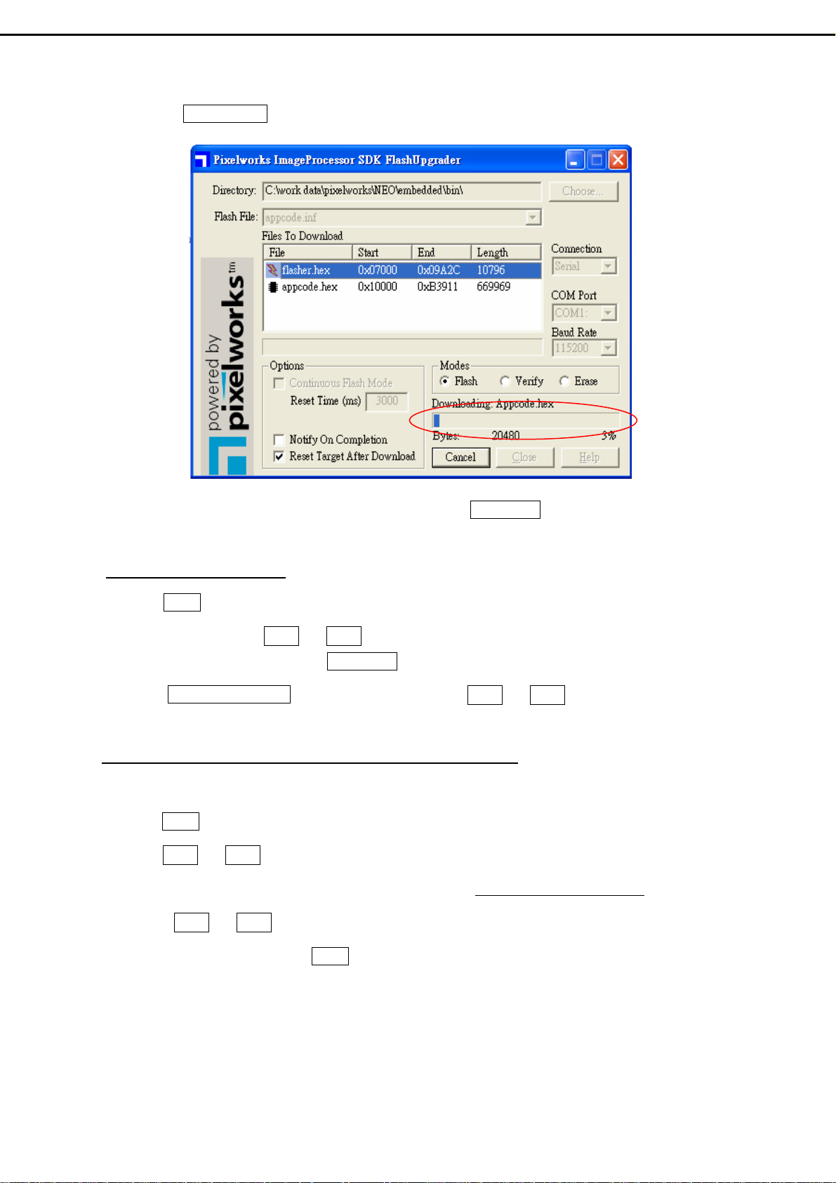
8) Turn the Main Power Switch to ON, and the file will automatically download.
√
9) When the message of completion or 100% appears, turn the Main Power Switch to OFF and then to
ON .
Step 3 : Initial EEPROM
1) Press Power Button to turn on the LCD-TV. (Power Indicator: Green color)
1) Use right hand to press Ch ▽ and Ch △ buttons simultaneously, and keep pressing them ( do not
release) . Use left hand to turn the Main Power Switch to OFF and then ON.
3) When UPDATE EEPROM appears on the screen, release Ch ▽ and Ch △ buttons, which you’re
pressing.
Step4 : Enter Factory mode to check the firmware version
1) Press Power Button to turn on the LCD-TV. (Power Indicator: Green color)
2) Press Ch ▽ and Ch △ buttons simultaneously, and keep pressing them ( do not release) .
3) When the version appears at the bottom of the screen such as V32FCBB-U21-MP-1.0-0214,
release Ch ▽ and Ch △ buttons you are pressing. Now the LCD-TV is in Factory Mode.
4) To exit the Factory Mode, press Power Button to turn off and then on the LCD-TV .
- 55 -
 Loading...