

Page 1

Motherboard
User's Guide
November 1998
5728892203 (Rev 2) T3274
Page 2

Copyright Notice
All rights reserved. No part of this publication may be reproduced, stored in a
retrieval system, or transmitted by any means, electronic, mechanical,
photocopying, recording, or otherwise, without prior written permission from
us. No patent liability is assumed with respect to the use of information
contained herein. While every precaution has been taken in the preparation
of this publication, we assume no responsibility for errors or omissions.
Neither is any liability assumed for damages resulting from the use of the
information contained herein.
The information contained in this publication is subject to change without
prior notice.
Trademark Acknowledgement
Intel is a registered trademark of Intel Corporation.
All other products mentioned herein are trademarks or registered
trademarks of their respective holders.
Page 3

Federal Communications Commission (FCC)
Statement
FCC Notice - Part 15
This equipment has been tested and found to comply with the limits for
a Class B digital device, pursuant to Part 15 of the FCC rules. These
limits are designed to provide reasonable protection against harmful
interference in a residential installation. This equipment generates,
uses and can radiate radio frequency energy and, if not installed and
used in accordance with the instructions, may cause harmful
interference to radio communications. However, there is no guarantee
that interference will not occur in a particular installation. If this
equipment does cause harmful interference to radio or television
reception, which can be determined by turning the equipment on and off,
the user is encouraged to try to correct the interference by one or more
of the following measures:
♦ Reorient or relocate the receiving antenna.
♦ Increase the separation between the equipment and the
receiver.
♦ Connect the equipment into an outlet on a circuit different from
that to which the receiver is connected.
♦ Consult the dealer or an experienced radio/TV technician for
help.
Use only shielded cables to connect I/O devices to this equipment.
You are cautioned that changes or modifications not expressly
approved by the party responsible for compliance could void your
authority to operate the equipment.
Canadian Department of Communication Radio
Frequency Interference Statement
This Class B digital apparatus meets all requirements of the Canadian
Interference-Causing Equipment Regulations.
Page 4

About This Guide
Congratulations on your purchase of this new motherboard.
This user's guide provides information on the installation and
setup procedures for your new motherboard.
Chapter 1: Specifications lists the standard features and
technical specifications of the motherboard.
You can find the motherboard layout in Chapter 2: Connectors
and Jumpers. Through this chapter, you can acquaint yourself
with the functions and locations of different connectors and
jumpers on your motherboard.
For information on BIOS Setup Utility, please refer to Chapter 3:
BIOS Setup. You may need to look into this chapter if you are
installing new peripherals into your system, or would like to
change system settings such as power management, ...
If you need to install or replace CPU or memory, refer to
Chapter 4: Installation.
For procedures on device driver installations, refer to Chapter
5: Device Driver Installations.
Page 5

Table of Contents
CHAPTER 1: SPECIFICATIONS
STANDARD FEATURES...................................................................................1-1
TECHNICAL SPECIFICATIONS .......................................................................1-2
CPU (CENTRAL PROCESSING UNIT)................................................................1-2
INTEL 440 BASIC PC PROCESSOR ....................................................................1-2
POWER MANAGEMENT ....................................................................................1-2
MEMORY ........................................................................................................1-3
BUILT-IN I/OS .................................................................................................1-3
INTEGRATED ATI RAGE IIC 1X AGP (RAGE PRO TURBO 2X AGP) CONTROLLER1-4
INTEGRATED ESS SOLO-1 PCI SOUND CHIP....................................................1-4
WAKE-ON-LAN (WOL) FEATURE......................................................................1-4
ENVIRONMENTAL SPECIFICATIONS ............................................................1-4
AMBIENT TEMPERATURE .................................................................................1-4
HUMIDITY.......................................................................................................1-4
UNIT DIMENSIONS..........................................................................................1-4
CHAPTER 2: CONNECTORS & JUMPERS
PARTS OF THE MOTHERBOARD ...................................................................2-2
MOTHERBOARD LAYOUT.............................................................................2-3
QUICK REFERENCE.........................................................................................2-4
DESCRIPTION ON CONNECTORS & JUMPERS.............................................2-5
CHAPTER 3: BIOS SETUP
ENTERING SYSTEM SETUP...........................................................................3-2
STANDARD CMOS SETUP............................................................................3-3
ADVANCED CMOS SETUP ............................................................................3-5
ADVANCED CHIPSET SETUP........................................................................3-7
POWER MANAGEMENT SETUP ..................................................................3-11
PCI/PLUG AND PLAY SETUP.......................................................................3-14
PERIPHERAL SETUP .....................................................................................3-17
AUTO DETECT HARD DISKS.......................................................................3-18
CHANGE USER PASSWORD...........................................................................3-19
CHANGE SUPERVISOR PASSWORD..............................................................3-19
CHANGE LANGUAGE SETTING....................................................................3-20
AUTO CONFIGURATION WITH OPTIMAL SETTINGS.............................3-20
AUTO CONFIGURATION WITH FAIL SAFE SETTINGS ............................3-20
SAVE SETTINGS AND EXIT..........................................................................3-21
EXIT WITHOUT SAVING..............................................................................3-21
Page 6

CHAPTER 4: INSTALLATION
CPU INSTALLATION.......................................................................................4-2
MEMORY INSTALLATION.............................................................................4-4
CHAPTER 5: DEVICE DRIVERS INSTALLATION
ESS PNP AUDIO SYSTEM..............................................................................5-1
ATI RAGE VGA DRIVER................................................................................5-5
Page 7

hapter 1
Specifications
This chapter lists standard features and technical specifications
of your motherboard.
Standard Features
P High performance system using Intel Celeron, Mendocino
or Pentium II CPU
P Designed using Intel 440 Basic PC processor
P Intel 82443EX (82443LX) PCI/AGP controller (PAC)
P Intel 82371EB PCI/ISA/IDE Xcelerator (PIIX4E)
P Integrated ATI Rage IIC 1X AGP (Rage Pro Turbo 2X AGP)
controller
P Integrated IDE, USB and DMA controllers
P 2MB Flash ROM with AMI BIOS
P Two 3.3V, 168-pin DIMM sockets, for maximum of 256MB
SDRAM memory
P Integrated ESS Solo-1 PCI sound chip
P Integrated SMC FDC37M707QFP Super I/O controller
P Supports ACPI 1.0 and APM 1.2 power management, Plug
& Play compatible and single-jumper configuration
P Built-in ports: serial port, parallel, PS/2 keyboard, PS/2
mouse, IrDA-compatible interface, USB ports x2, game/
MIDI port, microphone in, audio line in, and audio line out
P Expansion slots: ISA slot x1, PCI slots x2
P micro-ATX form-factor, ATX backwards compatible
P Runs under Windows 98
C
Page 8

1-2 Chapter 1: Specifications
Technical Specifications
CPU (Central Processing Unit)
Ÿ Advanced Intel CPU: Single Celeron à 266MHz core without
L2 cache; Mendocino à 300MHz core with 128KB L2 cache
integrated on the CPU die; or Pentium II à
233/266/300/333MHz core with 512KB L2 cache
Ÿ 66MHz CPU-Host bus speed
Ÿ Supports all Pentium II processor speeds, voltages, and bus
frequencies
Ÿ Slot 1 connector
Ÿ Numeric Coprocessor that significantly increases the speed
of floating-point operations and complies with ANSI/IEEE
standard 754-1985
Intel 440 Basic PC Processor
Ÿ Intel 82443EX (82443LX) PCI/AGP controller (PAC):
Integrated PCI bus mastering controller and Integrated
Accelerated Graphics Port (AGP) controller
Ÿ Intel 82371EB PCI/ISA/IDE Xcelerator (PIIX4E)
Ÿ Supports up to four IDE drives or devices: Multifunction
PCI-to-ISA bridge; USB and DMA controllers; two fast IDE
interfaces; power management logic; real-time clock
Power Management
Ÿ PC97 compliant APM (Advanced Power Management) 1.2
power management feature supported
Ÿ ACPI (Advanced Configuration and Power Interface) 1.0
power management feature supported in hardware. To
enable this feature, OS support and BIOS upgrade is
necessary.
Page 9

Technical Specifications 1-3
Memory
Ÿ 2MB Flash ROM with AMI BIOS
Ÿ Two DIMM (dual inline memory module) sockets provided for
expansion to 256MB maximum memory
Ÿ 168-pin 3.3V SDRAMs1 supported, memory access time of
SDRAMs must be 66MHz
Ÿ 64-bit non-ECC memory
Ÿ Different sizes of SDRAMs can be installed, BIOS
automatically detects the memory size
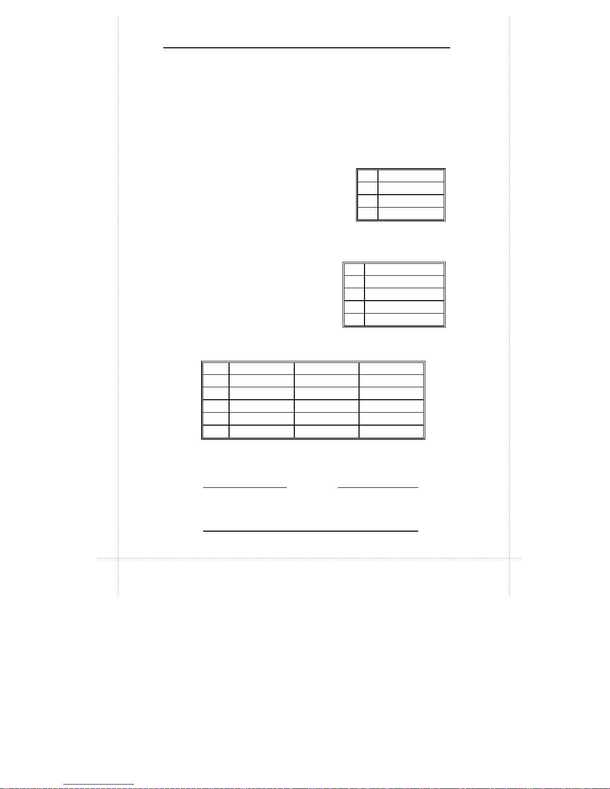
Ÿ Single- or double-sided SDRAMs in the following sizes are
supported:
DIMM Size Non-ECC type
8MB 1Mbit x 64
16MB 2Mbit x 64
32MB 4Mbit x 64
64MB 8Mbit x 64
128MB 16Mbit x 64
Built-in I/Os
Ÿ SMC FDC37M707QFP Super I/O controller
Ÿ Floppy Disk Controller (FDC)
Ÿ FIFO serial port and multi-mode parallel port
Ÿ PS/2 Keyboard and mouse controller
Ÿ IrDA-compatible interface
Ÿ Real-time clock/calendar
Ÿ CMOS RAM to maintain system configuration
Ÿ Two USB (Universal Serial Bus) port interfaces
Ÿ Game/MIDI port
1
SDRAM (Synchronous DRAM) improves memory performance by having
memory access time in synchronous with memory clock cycle. This simplifies the
timing design and increases memory speed since all timing is dependent on the
number of memory clock cycles.
Page 10

1-4 Chapter 1: Specifications
Ÿ Microphone in jack, audio line in jack, and audio line out jack
Ÿ Expansion slots: PCI slots x2, ISA slot x1
Integrated ATI Rage IIC 1X AGP (Rage Pro Turbo 2X
AGP) Controller
Integrated ESS Solo-1 PCI Sound Chip
Wake-on-LAN (WOL) feature
This feature enables a management application to remotely
power up your system, perform remote PC setup, update and
perform asset tracking after office hours and on weekends so
that daily LAN traffic is kept to a minimum and users are not
interrupted.
Environmental Specifications
Ambient Temperature
Operating: 50 °F to 104 °F (10 °C to 40 °C)
Non-operating: 5 °F to 140 °F (- 15 °C to 60 °C)
NOTE: Safety regulations for operating temperature is set at 25°C ±5°C.
Humidity
Operating: 15% to 80%, no condensation
Non-operating: 10% to 90%, no condensation
Unit Dimensions
Motherboard: 225.4 x 243.8 mm
Specifications are subject to change without prior notice.
REMARK
Page 11

hapter 2
Connectors & Jumpers
This chapter provides the layout, descriptions and functions of
the connectors and jumpers of your motherboard.
There are a number of connectors and jumpers on the
motherboard. Connectors allow you to connect to different
peripherals and/or devices. Jumpers, on the other hand,
provide you flexibility and different functions when set to different
values.
These jumpers were set to factory default before shipping,
which gives you the best performance. You should not alter
these settings unless you are sure of what you are doing. If you
want to change any setting, please make sure that the computer
has been turned OFF and make a note of what the original
settings are. This way, you can always revert to the original
settings if the new settings do not work.
C
Page 12
2-2 Chapter 2: Connectors & Jumpers
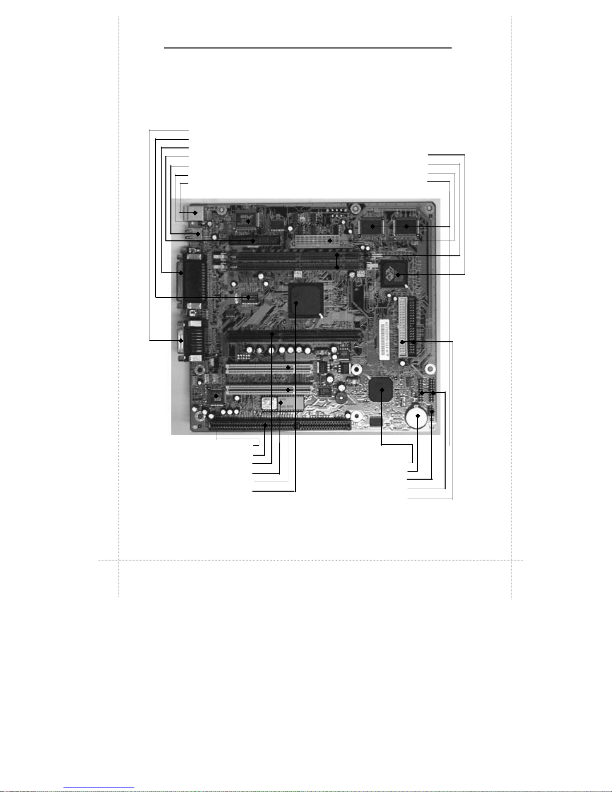
Parts of the Motherboard
AGP Chip
DIMM Sockets
ATX Power Connector
Video SGRAM
Game, Mic, Audio Out and Audio In Ports
Clock IC
Parallel, Video Out and Serial Port
FDD Connector
USB Ports x2
Super I/O Chip
Mouse/Keyboard Port
Sound Chip
ISA Slot
Slot1 (CPU Slot)
Flash ROM
PCI Slots
Intel 82443EX (82443LX)
Chipset
Intel PIIX4E Chip
Battery
CPU Frequency Select Jumper
Front Panel Connectors
IDE Connectors
Page 13
Motherboard Layout 2-3
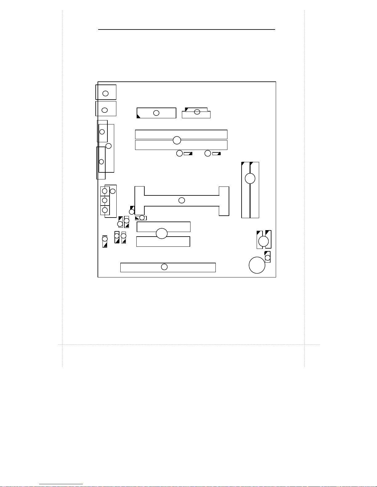
Motherboard Layout
JKB/MS
JUSB
JPRT JCOM1 JVGA JGAME JMIC JIN JOUT
JMPEG
JWOL
JCD2
JPCI1
JPCI2
JISA
Battery
JIDE1 JIDE2 JFRONT
JFAN
JFAN-C
JDIMM2
JDIMM1
JFDD
JATX
1
2
3
4
5
7
6
12
8
9
10
13
14
16
11
SLOT1 (CPU )
15
JCD1 JWOR
18
19 17
20
JCD
JPHONE
22
23 24
21
26
JFRONT1
JCPU
27
25
Page 14

2-4 Chapter 2: Connectors & Jumpers
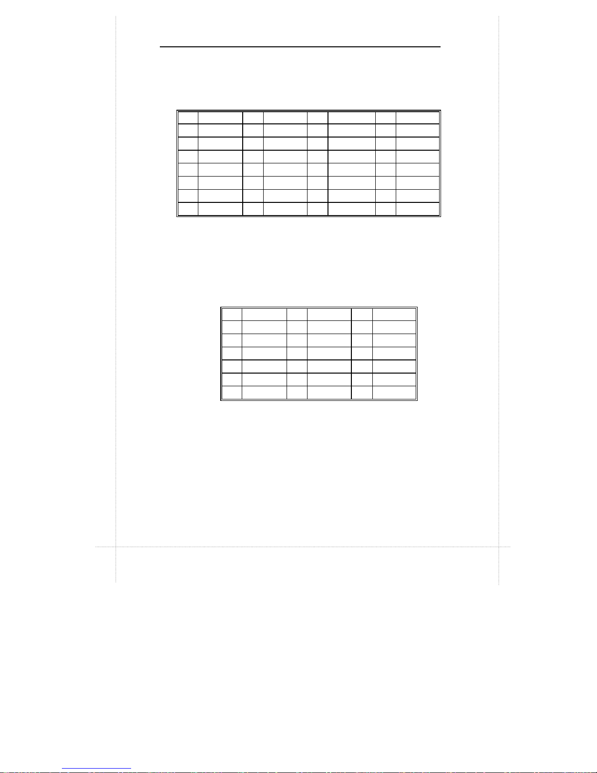
Quick Reference
Pointer
No.
Jumpers/
Connectors
Function Page
1 JKB/MS PS/2 Keyboard/Mouse Connector 2-5
2 JUSB USB Connector 2-5
3 JFDD Floppy Drive Connector 2-9
4 JATX Power Supply Connector 2-10
5 JCOM1 Serial Port Connector 2-5
6 JVGA VGA Port Connector 2-6
7 JPRT Print Port Connector 2-6
8 JDIMM1, JDIMM2 DIMM Sockets -
9 JFAN CPU Fan 2 Headers 2-10
10 JFAN-C CPU Fan 1 Headers 2-10
11 JIDE1, JIDE2 PCI IDE Connectors 2-13
12 JOUT Audio Line Out Connector 2-7
13 JIN Audio Line In Connector 2-7
14 JMIC Audio Mic In Connector 2-7
15 JGAME Game/MIDI Port Connector 2-7
16 SLOT1 CPU Slot 17 JWOR Wake-on-Ring Connector 2-8
18 JWOL Wake-on-LAN Connector 2-8
19 JCD1 ATAPI/CD Audio Connectors 2-8
20 JCD2 ATAPI/CD Audio Base & Pin 2-8
21 JPCI1, JPCI2 PCI Bus Connectors 2-11
22 JPHONE Fax/modem Speaker Connectors 2-8
23 JMPEG MPEG Connector 2-9
24 JCD ATAPI/CD Audio Connectors 2-8
25
JFRONT,
JFRONT1
Front Panel I/O Connectors 2-14
26 JISA1 ISA Bus Connector 2-12
27 JCPU CPU Frequency Select Jumper 2-15
Page 15

Description on Connectors & Jumpers 2-5
Description on Connectors & Jumpers
1
PS/2 Keyboard/Mouse Connector (JKB/MS)
The PS/2 enhanced
keyboard and mouse is
connected to the computer
via a female mini-DIN
connector JKB/MS that is
mounted on the
motherboard.
2
USB Connector (JUSB)
The USB (Universal Serial Bus) connector,
JUSB, is a 2-layered connector mounted
on the motherboard for connecting up to
two USB devices.
3
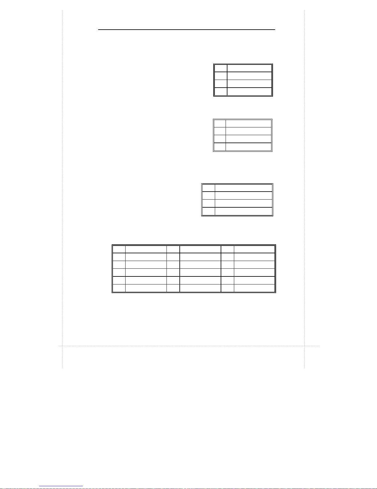
Serial Port Connector (JCOM1)
JCOM1 is a male DB9 (9-pin) serial port connector built-in
on the motherboard. To enable or disable this, perform
BIOS Setup.
Pin Signal Pin Signal
1
Data 4
+5V
(fused)
2
NC 5
CLK
3
GND 6
NC
Pin Signal
1 Power
2
USBP0#
[USBP1#]
3
USBP0
[USBP1]
4
GND
Pin Signal Pin Signal Pin Signal
1
DCD 4 DTR# 7
RTS
2 Serial In# 5
GND 8
CTS
3 Serial Out# 6
DSR 9
RI
Page 16
2-6 Chapter 2: Connectors & Jumpers
4
Print Port Connector (JPRT)
JPRT is a female DB25 (25-hole) parallel port built-in on the
motherboard. You can select the mode of parallel port
through BIOS Setup utility.
5
VGA Port Connector (JVGA)
VGA interface is built-in. Video cable of a VGA/SVGA
monitor is connected to JVGA (15-hole) of the
motherboard.
Pin Signal Pin Signal Pin Signal Pin Signal
1 Strobe# 7 Data bit 5 13 Select 19 GND
2 Data bit 0 8 Data bit 6 14 Auto Feed# 20 GND
3 Data bit 1 9 Data bit 7 15 Fault# 21 GND
4 Data bit 2 10 ACK# 16 INIT# 22 GND
5 Data bit 3 11 Busy 17 SLCT IN# 23 GND
6 Data bit 4 12 Error 18 GND 24 GND
25
GND
Pin Signal Pin Signal Pin Signal
1
R 7
GND 13 HSYNC
2
G 8
GND 14 VSYNC
3
B 9
NC 15 MONID2
4
NC 10 GND 16 GND
5
GND 11
NC 17 GND
6
GND 12 MONID1
Page 17
Description on Connectors and Jumpers 2-7
6
Audio Line In Connector (JIN)
JIN is for connecting audio output of
peripheral devices such as
CD/cassette player.
7
Audio Line Out Connector (JOUT)
JOUT is for connection to an
amplifier system or other audio
peripheral devices.
8
Audio Mic In Connector
(JMIC)
JMIC is for connection to an
external microphone.
9
Game/MIDI Port Connector (JGAME)
JGAME is a 15-pin connector mounted on the motherboard
for connection of joystick or MIDI devices.
Pin
Signal
1
GND
2
Audio Left In
3 Audio Right In
Pin
Signal
1
GND
2 Audio Left Out
3 Audio Right Out
Pin
Signal
1
GND
2
Mono In
3 Electret Bias Voltage
Pin
Signal Pin
Signal Pin
Signal
1 +5V (fused) 6 GP1 (JSY1R) 11 GP2 (JSX2R)
2 GP4 (JSBUT0) 7 GP5 (JSBUT1) 12 MIDI-OUTR
3 GP0 (JSX1R) 8 +5V (fused) 13 GP3 (JSY2R)
4
GND 9 +5V (fused) 14 GP7 (JSBUT3)
5
GND 10 GP6 (JSBUT2) 15
MIDI-INR
Page 18
2-8 Chapter 2: Connectors & Jumpers
10
Fax/Modem Speaker Connector (JPHONE)
JPHONE is for connection to an add-on fax/modem card's
speaker.
11
Wake-on-LAN Connector (JWOL)
Wake-on-LAN is a key feature for
corporate systems. JWOL jumper
allows a management application to
remotely power on a computer that is
originally turned off.
12
Wake-on-Ring Connector (JWOR)
This jumper is for connection to
an optional modem card to turn on
the system when a modem phone
call is received.
13
ATAPI CD Audio
Connectors (JCD, JCD1, JCD2)
The audio output signals of CD-ROM drive is connected to
JCD, JCD1 or JCD2.
You can connect to only one of these at a time.
Check the output signals from your CD-ROM
drive manual.
Pin
Signal
1 5V standby
2
Ground
3 MP_Wakeup
Pin
Signal
1
Telephone In
2
GND
3
GND
4 Telephone Out
Pin
JCD JCD1 JCD2
1 CD_IN-Left CD_IN-Left CD_IN-Left
2 GND GND GND
3 GND CD_IN-Right CD_IN-Right
4 CD_IN-Right
GND GND
Type Connector Connector Base & Pin
NOTE
Page 19

Description on Connectors and Jumpers 2-9
14
MPEG Connector (JMPEG)
JMPEG is for
connecting MPEG-I
audio in signals.
15
Floppy Drive Connector (JFDD)
Floppy disk drives are connected to the motherboard by
using a 34-pin flat cable connected to JFDD.
Pin
Signal
1 CD/MPEG Right Channel Input
2
GND
3
GND
4 CD/MPEG Left Channel Input
Pin Signal Pin
Signal
1
GND 2
DENSEL
3
GND 4
Reserved
5
Key 6
FDEIN
7
GND 8
FDINDX# (Index)
9
GND 10
FDMO0# (Motor Enable A)
11 GND 12
FDDS1# (Drive Select B)
13 GND 14
FDDS0# (Drive Select A)
15 GND 16
FDMO1# (Motor Enable B)
17 MSEN1 18 FDDIR# (Stepper Motor Direction)
19 GND 20
FDSTEP# (Step Pulse)
21 GND 22
FDWD# (Write Data)
23 GND 24
FDWE# (Write Enable)
25 GND 26
FDTRK0# (Track 0)
27 MSEN0 28
FDWPD# (Write Protect)
29 GND 30
FDRDATA# (Read Data)
31 GND 32
FDHEAD# (Side 1 Select)
33 GND 34
DSKCHG# (Diskette Change)
Page 20

2-10 Chapter 2: Connectors & Jumpers
16
CPU Fan 2 Header (JFAN)
JFAN becomes active when the
system’s power is turned on.
17
CPU Fan 1 Header (JFAN-C)
JFAN-C becomes active when the
system is in suspend mode.
18
Power Supply Connector (JATX)
The 20-pin connector from the switching power supply is
connected to JATX.
If the switching power supply used is an ATX-compliant
power supply, remote power on/off is supported and the
system’s power can be turned off through software control.
This feature is called soft-off control.
Soft-off control allows your computer to automatically go
back to the power state (on, off, or suspend) after being
interrupted either by power outage or by disconnection of
power cord. To enable this feature, your system’s
advanced power management must be enabled both in
BIOS setup utility and in the operating system.
Pin
Signal
1
GND
2
+12V
3
GND
Pin
Signal
1
X
2 FAN_CTRL (+12V)
3
GND
Pin Signal Pin Signal Pin Signal Pin Signal
1 +3.3V 6 +5V 11 +3.3V 16 GND
2 +3.3V 7 GND 12 -12V 17 GND
3 GND 8 PWRGD 13 GND 18
-5V
4 +5V 9 +5VSB 14 PS-ON# 19
+5V
5 GND 10 +12V 15 GND 20
+5V
Page 21

Description on Connectors and Jumpers 2-11
19
PCI Bus Connectors (JPCI1, JPCI2)
There are a total of two PCI slots available on the
motherboard, namely, JPCI1 and JPCI2.
Pin
A B Pin
A B
1 GND -12 V 32
AD16 AD17
2 +12 V GND 33
+3.3 V C/BE2#
3 +5 V GND 34 FRAME# GND
4 +5 V No Connect 35
GND IRDY#
5 +5 V +5 V 36
TRDY# +3.3 V
6 PIRQ#A +5 V 37
GND DEVSEL#
7 PIRQ#C PIRQ#B 38
STOP# GND
8 +5 V PIRQ#D 39
+3.3 V PLOCK#
9 Reserved No Connect 40
+5 V PERR#
10 +5 V (I/O) Reserved 41
+5 V +3.3 V
11 Reserved No Connect 42
GND SERR#
12
GND GND 43
PAR +3.3 V
13
GND GND 44
AD15 C/BE1#
14 Reserved Reserved 45
+3.3 V AD14
15 PCIRST# GND 46
AD13 GND
16 +5 V (I/O) CLK 47
AD11 AD12
17
GNT# GND 48
GND AD10
18
GND REQ# 49
AD09 GND
19 PCI_PM# +5 V (I/O) 50
Key Key
20
AD30 AD31 51
Key Key
21
+3.3 V AD29 52
C/BE0# AD08
22
AD28 GND 53
+3.3 V AD07
23
AD26 AD27 54
AD06 +3.3 V
24
GND AD25 55
AD04 AD05
25
AD24 +3.3 V 56
GND AD03
26
AD26 C/BE3# 57
AD02 GND
27
+3.3 V AD23 58
AD00 AD01
28
AD22 GND 59 +5 V (I/O) +5 V (I/O)
29
AD20 AD21 60 PU_ACK64#
+5V
30
GND AD19 61
+5 V +5 V
31
AD18 +3.3 V 62
+5 V +5 V
Page 22

2-12 Chapter 2: Connectors & Jumpers
20
ISA Bus Connector (JISA1)
JISA1 is an ISA slot available on the motherboard for
expansion purposes.
Pin
B A D C
1
GND IOCHK# MEMCS16#
SBHE#
2 BRSTDRV SD7 IOCS16# LA23
3
+5 V SD6 IRQ10 LA22
4
IRQ9 SD5 IRQ11 LA21
5
-5 V SD4 IRQ12 LA20
6
DRQ2 SD3 IRQ15 LA19
7
-12 V SD2 IRQ14 LA18
8 ZEROWS# SD1 DACK0# LA17
9
+12 V SD0 DRQ0 MEMR#
10
GND IOCHRDY DACK5# MEMW#
11 SMEMW# AEN DRQ5 SD8
12 SMEMR# SA19 DACK6# SD9
13
IOW# SA18 DRQ6 SD10
14
IOR# SA17 DACK7# SD11
15 DACK3# SA16 DRQ7 SD12
16
DRQ3 SA15 +5 V SD13
17 DACK1# SA14 RMASTER#
SD14
18
DRQ1 SA13 GND SD15
19 REFRESH#
SA12
20 SYSCLK SA11
21
IRQ7 SA10
22
IRQ6 SA9
23
IRQ5 SA8
24
IRQ4 SA7
25
IRQ3 SA6
26 DACK2# SA5
27
TC SA4
28
BALE SA3
29
+5 V SA2
30
OSC1 SA1
31
GND SA0
Key Key
Page 23

Description on Connectors and Jumpers 2-13
21
PCI IDE Connectors (JIDE1, JIDE2)
The PCI-bus IDE type devices are connected to the
motherboard by using a 40-pin Daisy-chained cable to
JIDE1 and JIDE2. JIDE1 is for the primary IDE connector
while JIDE2 is for the secondary IDE connector. Those
signals in brackets are signals for the secondary IDE
connector.
Pin
Signal Pin
Signal
1 Reset IDE
2 GND
3 Data 7
4 Data 8
5 Data 6
6 Data 9
7 Data 5
8 Data 10
9 Data 4
10 Data 11
11 Data 3
12 Data 12
13 Data 2
14 Data 13
15 Data 1
16 Data 14
17 Data 0
18 Data 15
19 GND
20 Key
21 DDRQ0 [DDRQ1]
22 GND
23 I/O Write#
24 GND
25 I/O Read#
26 GND
27 IOCHRDY
28 P_ALE (Cable Select pull-up)
29 DDACK0# [DDACK1#]
30 GND
31 IRQ14 [IRQ15]
32 Reserved
33 Address 1
34 Reserved
35 Address 0
36 Address 2
37
Chip Select 1P# [Chip
Select 1S#]
38
Chip Select 3P# [Chip
Select 3S#]
39 Activity#
40 GND
Page 24

2-14 Chapter 2: Connectors & Jumpers
22
Front Panel I/O Connectors (JFRONT, JFRONT1)
Note that JFRONT connector is a manufacturer reserved
function and is therefore not available to the user.
JFRONT1 allows connection of I/O controls to the front
panel.
Pin descriptions as follows:
h h h h h h h h h
h h h h h h h h h
Pin
Signal Pin
Signal
1 Vcc (HD-LED(+)) 2 HD-LED (-)
3 Vcc 4 Power_LED (+) (Green)
5 GND 6 Power_LED (+) (Yellow)
7 GND 8 GND (Power_LED(-))
9 GND 10
POWER-ON
11
No Connect 12
No Connect
13
GND 14
Reset Switch
15
No Connect 16
No Connect
17
18
1
2
Reset Switch –
connects to
the front panel’s reset
Power-On Switch – connects to the
front panel’s power on switch.
Hard Disk LED – connects to
the HDD LED of the front panel.
This LED indicates that system
is currently accessing hard
Power LED – connects to the front panel’s power LED. If
power LED of front panel is a single-
color LED, connect pins
4 and 8 or pins 6 and 8 to it.
Suspend LED –
available only if power LED of front panel is
a two-
color LED. In this case, connect pins 4, 6 and 8 to the
power LED of the front panel.
Page 25

Description on Connectors and Jumpers 2-15
23
CPU Frequency Select Jumper (JCPU)
JCPU jumper is used to set CPU speed.
JCPU settings for different CPUs:
CPU Model Frequency Ratio Bus Freq. 1-2 3-4 5-6 7-8
Celeron 266MHz 4X 66MHz OUT IN IN IN
Celeron 300MHz 4.5X 66MHz OUT IN OUT OUT
Celeron
300AMHz
300MHz 4.5X 66MHz OUT IN OUT OUT
Celeron 333MHz 5X 66MHz OUT OUT IN IN
Pentium II 233MHz 3.5X 66MHz IN OUT OUT OUT
Pentium II 266MHz 4X 66MHz OUT IN IN IN
Pentium II 300MHz 4.5X 66MHz OUT IN OUT OUT
Pentium II 333MHz 5X 66MHz OUT OUT IN IN
h h h h
h h h h
h h h h
h h h h
h h h h
h h h h
h h h h
h h h h
h h h h
h h h h
h h h h
h h h h
h h h h
h h h h
h h h h
h h h h
Celeron 266MHz
1
2
7
8
Celeron 300MHz
1
2
7
8
Celeron 300AMHz
1
2
7
8
Celeron 333MHz
1
2
7
8
Pentium II 233MHz
1
2
7
8
Pentium II 266MHz
1
2
7
8
Pentium II 300MHz
1
2
7
8
Pentium II 333MHz
1
2
7
8
Page 26

Page 27

hapter 3
BIOS Setup
The AMI BIOS Setup Utility of your system is discussed in this
chapter.
The system Basic Input and Output System (BIOS) is the
interface between the hardware and the operating system
software. Its function is to provide a series of software
interrupts and functions that control operations on certain
devices connected to your system. Aside from this, it performs
a series of Power On Self Test (POST) every time you boot the
system. POST checks your actual system configuration with
the system configuration data stored in a non-volatile memory
known as CMOS RAM. These tests are to ensure that your
system is properly configured to recognize the devices such as
memory, FDD, HDD, etc.
Usually, you may need to perform setup due to the following
circumstances:
Ÿ Adding or removing devices to or from the system, such as
FDD, HDD, adapter cards, or memory
Ÿ Changing the type of video display
Ÿ Setting the built-in clock/calendar to the correct time and/or
date
Ÿ Enabling or disabling special features such as power
management functions, system passwords, etc.
Ÿ Setting or resetting configuration data if these were
accidentally lost or if the on-board battery was replaced.
C
Page 28

3-2 Chapter 3: BIOS Setup
Entering System Setup
When you turn on your system, the following message is shown
while your system is executing POST:
Hit <DEL> if you want to run SETUP
In order to enter Setup Utility, you have to press <DEL> key fast
enough before it starts up the operating system.
If you are not able to enter the Setup Utility through this, reboot
your computer and repeat the above procedure.
If the computer detects discrepancies between your CMOS
data and actual system configuration, it will prompt you with an
error message and request you to run setup. Just the same,
you can enter setup by pressing <DEL> key.
The following screen appears upon entering Setup Utility:
You can use up and down arrow keys to move to the desired
option, then press <Enter> on that option to select it or to open
its sub-menu. Press <ESC> to return to the previous menu or
to exit setup utility.
Page 29

Standard CMOS Setup 3-3
If you want to modify the option for an item, you have to select
that item and press <PgUp> or <PgDn> key. The options for an
item will be shown either at the bottom of the screen, or at the
right column of the screen.
To change the color of text and background of your screen
display, press <F2> or <F3>.
Standard CMOS Setup
Standard CMOS setup allows you to set the system date and
time; to specify floppy disk drives installed in your system; to
indicate up to four IDE type storage devices (HDDs or CD-ROM
drive); to enable or disable virus protection; and to know the
base and extended memory size. When this option is selected,
the following appears on screen:
Page 30

3-4 Chapter 3: BIOS Setup
Options and description of each item as follows:
Item Options Description
Date (mm/dd/yy) Month:day:year
Time (hh/mm/ss) hour:min:sec
Sets system date and time to
current date and time.
Floppy Drive A:
Floppy Drive B:
Not Installed
360 KB 5¼
1.2 MB 5¼
720 KB 3½
1.44 MB 3½
2.88 MB 3½
Selects the type of floppy drive
installed.
Pri Master
Pri Slave
Sec Master
Sec Slave
Not Installed
1
M
46
User
Auto
CD-ROM
Floptical
Selects type of IDE devices
installed.
Auto - BIOS automatically
detects hard disk
parameters.
User - You enter hard disk
parameters.
1~46 - Select parameters from
a pre-determined set of
values.
Floptical refers to removable
devices.
LBA Off
On
Selects On if the drive has a
capacity greater than 540MB.
Blk Off
On
On allows block mode data
transfers. Check if your hard
disk supports this mode. If it
does not support this mode,
data may be destroyed when
turned On.
PIO Auto
0
1
2
3
4
Selects PIO Mode of the IDE
device. It is best to select Auto
to let the BIOS detect the mode.
If you selected a mode that is
not supported by the IDE drive,
that drive will not work properly.
32Bit Off
On
On allows 32-bit data transfers.
Page 31

Advanced CMOS Setup 3-5
Boot Sector Virus
Protection
Disabled Protect the boot sector and
partition table of the hard disk
from virus intrusion when this is
enabled.
Base Memory
Extd Memory
N/A Detect and display the size of
base memory and extended
memory installed in your
system.
Advanced CMOS Setup
Advanced CMOS Setup allows you to configure basic system
performance parameters.
Options and description of each item as follows:
Item Options
Description
Quick Boot Disabled
Enabled
Enabled allows the BIOS to skip
certain tests to speed up boot
process. If enabled, the message "Hit
<DEL> if you want to run SETUP" will
not appear on screen during boot.
Page 32

3-6 Chapter 3: BIOS Setup
1st Boot Device
2nd Boot Device
3rd Boot Device
4th Boot Device
Disabled
IDE-0
IDE-1
IDE-2
IDE-3
Floppy
LS-120
ZIP Drive
CDROM
SCSI
Network
BIOS will attempt to read the boot
record from first, second, then third
device in the selected order until it is
successful in reading the boot record.
Initial Display
Mode
BIOS
Silent
BIOS displays AMIBIOS messages
before booting the system.
Floppy Drive
Swap
Disabled
Enabled
Enabled allows drive A: and B: to be
swapped.
Boot Up
Num-Lock
On
Off
On turns the Num Lock key off when
system is powered on.
PS/2 Mouse
Support
Enabled
Disabled
Enables or disables the support for
PS/2 type mouse.
Typematic Rate Slow
Fast
This option sets the rate at which
characters on the screen repeat when
a key is pressed and held down.
Password Check Always
Setup
Enables password checking:
Always - every time the system boots
Setup - if BIOS Setup Utility is
accessed
Boot to OS/2 >
64MB
No
Yes
Yes allows BIOS to run with OS/2 and
use more than 64MB of system
memory.
Page 33

Advanced Chipset Setup 3-7
C000, 16K
Shadow
C400, 16K
Shadow
C800, 16K
Shadow
CC00, 16K
Shadow
D000, 16K
Shadow
D400, 16K
Shadow
D800, 16K
Shadow
DC00, 16K
Shadow
Disabled
Enabled
Cached
Enables the shadowing of the
contents of selected ROM area. ROM
area not used by ISA adapter cards is
allocated to PCI adapter cards.
Disabled - contents of video ROM are
not copied to RAM.
Enabled - contents of video ROM area
from C0000h-C7FFFh are copied from
ROM to RAM for faster execution.
Cached - contents of video ROM area
from C0000h - C7fffh are copied from
ROM to RAM and can be written to or
read from cache memory.
Advanced Chipset Setup
Advanced Chipset Setup configures the functions of the chipset
used. Be sure you are familiar with the chipset before you
attempt to make any changes on these.
Page 34

3-8 Chapter 3: BIOS Setup
Options and description of each item as follows:
Item Options Description
SDRAM RAS To
CAS Delay
Specifies the length of the delay
inserted between the RAS and
CAS signals of the DRAM
system memory access cycle.
SDRAM RAS
Precharge
Timing
3 Clks
2 Clks
Specifies the length of the RAS
precharge part of the DRAM
system memory access cycle.
DRAM Integrity
Mode
Non-ECC
EC Only
ECC
Sets the type of system memory
checking:
Non-ECC - No error checking or
reporting done.
EC only - Multi-bit errors are
detected and reported as parity
errors. Single-bit errors are
corrected by the chipset.
Corrected bits are not written
back to DRAM.
ECC - Multi-bit errors are
detected and reported as parity
errors. Single-bit errors are
corrected by the chipset and
written back to DRAM.
Page 35

Advanced Chipset Setup 3-9
VGA Frame
Buffer USWC*
Enabled
Disabled
Enables or disables VGA video
frame buffer using USWC. Note
that older ISA card drivers may
not behave correctly if this option
is not set to Disabled.
PCI Frame Buffer
USWC
Enabled
Disabled
Enables or disables USWC
memory attribute. Enabling this
improves video performance
when a PCI video adapter is
installed.
Fixed Memory
Hole
Disabled
512KB-640KB
15 MB-16 MB
Specifies the location of an area
of memory that cannot be
addressed on the ISA bus.
CPU To PCI IDE
Posting
USWC Write I/O
Post
PCI 32-Clock
Target Timer
PCI To DRAM
Pipeline
Burst Write
Combining
Read Around
Write
Disabled
Enabled
Enables or disables the
corresponding items.
TypeF DMA Buffer
Control1
TypeF DMA Buffer
Control2
Channel-0
Channel-1
Channel-2
Channel-3
Disabled
Channel-5
Channel-6
Channel-7
Specifies the DMA channel
where TypeF buffer control is
implemented.
*
USWC - Uncacheable, Speculatable, Write-Combined
Page 36

3-10 Chapter 3: BIOS Setup
DMA-0 Type
DMA-1 Type
DMA-2 Type
DMA-3 Type
DMA-5 Type
DMA-6 Type
DMA-7 Type
Normal ISA Specifies the bus that the
specified DMA channel can be
used on.
AGP Aperture
Size
4 MB
8 MB
16MB
32MB
64MB
128MB
256MB
Specifies the amount of memory
that can be used by AGP
(Accelerated Graphics Port).
AGP Common
SERR#
Disabled
Enabled
Enabled permits a common
SERR# signal for AGP and the
standard PC bus.
AGP System
Error
Forwarding
Disabled
Enabled
Enabled allows AGP system
errors to be forwarded.
AGP Parity Error
Response
PIIX4 SERR#
USB Passive
Release
PIIX4 Passive
Release
PIIX4 Delayed
Transaction
Disabled
Enabled
Enables or disables the
corresponding items.
USB Function Disabled
Enabled
Enables or disables USB
functions.
USB Keyboard
Legacy Support
Disabled
Enabled
Enables or disables USB
keyboard and mouse if USB
function is enabled.
Page 37

PCI/Plug and Play Setup 3-11
Power Management Setup
Power Management Setup allows you to configure power
conservation features.
Page 38

3-12 Chapter 3: BIOS Setup
Options and descriptions of each item as follows:
Item Options Description
Power
Management/
APM
Disabled
Enabled
Enabled lets the BIOS control the
power conservation features.
Video Power Down
Mode
Hard Disk Power
Down Mode
Disabled
Standby
Suspend
Specifies the power state that the
display or hard disk enters after the
specified period of inactivity has
expired.
Standby Time Out
(Minute)
Suspend Time Out
(Minute)
Disabled
1
2
4
8
10
20
30
40
50
60
Specifies the length of period of
system inactivity while in full
power/standby state before it
enters standby/suspend power
state.
Throttle Slow Clock
Ratio
0-12.5%
12.5-25%
25-37.5%
37.5-50%
50-62.5%
62.5-75%
75-87.5%
Indicates the percentage of time the
STPCLK# signal is asserted while
in the thermal throttle mode.
Modem Use IRQ N/A
3
4
5
7
9
10
11
Sets the IRQ address used by
modem.
Page 39

PCI/Plug and Play Setup 3-13
Device 6 (Serial
port 1)
Device 7 (Serial
port 2)
Device 8 (Parallel
port)
Device 5 (Floppy
disk)
Device 0 (Primary
master IDE)
Device 1 (Primary
slave IDE)
Device 2
(Secondary
master IDE)
Device 3
(Secondary slave
IDE)
Monitor Enables event monitoring on the
selected item. Monitor allows BIOS
to enter Full On state if any activity
occurs on that specific item when
the computer is in a power saving
state.
Power Button
Function
On/Off
Suspend
When power button is pressed:
On/Off turns the computer on or of.
Suspend places the computer in
suspend mode or full power mode.
Wake on Ring
Wake on LAN
Disabled
Enabled
Enabled allows you to wake up the
system through modem or LAN.
RTC Alarm
Resume From
Soft-Off
Disabled
Enabled
Sets the RTC alarm to wake up the
system on a specified period.
RTC Alarm Date Every Day
01
M
31
RTC Alarm Hour 00
M
23
RTC Alarm Minute 00
M
59
Specifies the date and time to wake
up the system if 'RTC Alarm
Resume From Soft-Off' is enabled.
Page 40

3-14 Chapter 3: BIOS Setup
RTC Alarm Second 00
M
59
PCI/Plug and Play Setup
PCI/Plug and Play Setup configures PCI and Plug-and-Play
features.
Page 41

PCI/Plug and Play Setup 3-15
Options and descriptions of each item as follows:
Item Options Description
Plug and
Play-Aware
OS
No
Yes
Set this to Yes if your operating
system is aware of and follows the
Plug and Play specification.
Onboard Sound
Function
Disabled
Enabled
Enables or disables system's
onboard sound feature.
PCI Latency
Timer (PCI
Clocks)
32
64
96
128
160
192
224
248
Specifies the latency timings in
PCI clocks for all PCI devices.
PCI VGA
Palette
Snoop
Disabled
Enabled
This option must be set to
Enabled if any ISA adapter card
installed in the system requires
VGA palette snooping.
Allocate IRQ to
PCI VGA
Yes
No
Assigns an interrupt signal to the
PCI VGA card.
PCI IDE
Busmaster
Disabled
Enabled
Specifies if the IDE controller on
the PCI bus has bus mastering
capabilities.
PCI Slot1 IRQ
Priority
PCI Slot2 IRQ
Priority
Auto
3
4
5
7
9
10
11
Sets the interrupt priority of the PCI
slots.
DMA Channel 0
DMA Channel 1
DMA Channel 3
DMA Channel 5
DMA Channel 6
DMA Channel 7
PnP
ISA
Specifies which channels to
control the data transfers between
I/O devices and system memory.
Page 42

3-16 Chapter 3: BIOS Setup
IRQ3
IRQ4
IRQ5
IRQ7
IRQ9
IRQ10
IRQ11
IRQ14
IRQ15
PCI/PnP
ISA
Specifies which bus the specified
IRQ line is used on and allows you
to reserve interrupts for legacy ISA
adapter cards. If more interrupts
must be removed from the pool,
you can use these options to
reserve the IRQ by assigning an
ISA/EISA setting to it. Onboard I/O
is configured by the BIOS and are
configured as PCI/PnP.
IRQ14 and 15 will not be available
if onboard PCI IDE is enabled. If all
IRQs are set to ISA/EISA IRQ14
and 15 are allocated to the
onboard IDE, IRQ 9 will still be
available for PCI and PnP devices.
Reserved
Memory Size
Disabled
16K
32K
64K
Specifies the size of the memory
area reserved for legacy ISA
adapter cards.
Reserved
Memory
Address
C0000
C4000
C8000
CC000
D0000
D4000
D8000
DC000
Specifies the beginning address
(in hex) of the reserved memory
area. The specified ROM memory
area is reserved for use by legacy
ISA adapter cards if "Reserved
Memory Size" is not disabled.
Page 43

Peripheral Setup 3-17
Peripheral Setup
Peripheral Setup allows you to configure system I/O support.
Options and descriptions of each item as follows:
Item Options Description
OnBoard FDC Auto
Disabled
Enabled
Enables the floppy drive
controller on the motherboard.
Floppy Drive
Access
Read/Write
Read Only
Specifies the read/write access
mode that is set when booting
from a floppy drive.
OnBoard Serial
Port1
Auto
Disabled
3F8h/COM1
2F8h/COM2
3E8h/COM3
2E8h/COM4
Specifies the base I/O port
address of serial port 1/2.
OnBoard
Parallel Port
Auto
Disabled
378h
278h
3BCh
Specifies the base I/O port
address of the parallel port on
the motherboard.
Page 44

3-18 Chapter 3: BIOS Setup
Parallel Port
Mode
Normal
Bi-Directional
EPP
ECP
Normal à normal parallel mode
EPP (Enhanced Parallel Port) à
provide asymmetric bidirectional
data transfer driven by the host
device.
ECP (Extended Capabilities
Port) à achieve data transfer
rates of up to 2.5 Mbps. Uses
DMA protocal and provides
symmetric bidirectional
communication.
EPP Version 1.7
1.9
Options available only if ‘Parallel
Port Mode’ is EPP.
Parallel Port
IRQ
5
7
Specifies IRQ to be used by the
parallel port.
Parallel Port ECP
DMA Channel 0 1
3
Options available only if ‘Parallel
Port Mode’ is ECP.
On-Board IDE Disabled
Primary
Secondary
Both
Specifies the onboard IDE
controller channels to be used.
Auto Detect Hard Disks
Your system can automatically detect and configure the IDE
devices installed in your system. When you select this item
from the main menu, the Standard CMOS Setup menu will be
displayed to show you the results of the automatic detection.
Page 45

Save Settings and Exit 3-19
Change User Password
Change Supervisor Password
Passwords prevent unauthorized use of your computer. There
are two levels of security provided by your system, that is,
supervisor and user.
If "Password Check" item in the "Advanced CMOS Setup" is set
to "Always", you shall need your user password before you are
able to access your system. If it is set to "Supervisor", you shall
need supervisor password if configuration changes are to be
made. However, note that you need to set your supervisor
password first before setting your user password.
To enter new password, change a password or disable a
password, choose "Change User Password" or "Change
Supervisor Password" from the main menu.
To enter a new password, you will be required to type in that
password twice (for confirmation purposes) before the system
will accept that password. Your system accepts passwords
that contain maximum of six characters. When entering the
password, "*" appears in place of the characters you typed. If
password (supervisor) is successfully installed, the system
displays the message below:
New supervisor password installed, press any key to continue
If you want to change an existing password, system will prompt
you to enter the old password, then enter the new password
twice. The same message appears on screen when password
installation is successful.
If you want to disable or clear a password, just press <Enter>
key when you are prompted to type in new password. The
following message (for supervisor password) is displayed:
Supervisor password disabled, press any key to continue
Page 46

3-20 Chapter 3: BIOS Setup
Note that if you disabled the supervisor password, user
password is automatically disabled, too.
Wrong password entered provides the following message:
Incorrect password, press any key to continue
If you forgot your password, you have to clear CMOS data and
reconfigure the system.
Change Language Setting
This item is intended for users to select the type of language
characters displayed on screen. Currently, only "English" is the
available option.
Auto Configuration with Optimal
Settings
Auto Configuration with Fail Safe
Settings
Two sets of default values were permanently stored in your
system allowing it to load these automatically if there are invalid
CMOS data. If you want to load one of these, you can select it
from the main menu.
Optimal settings are best-case values that would optimize
system performance. If CMOS data are corrupt, system will
load these settings automatically. Fail safe settings offer the
most stable settings but are far from optimal system
performance. Use this option as a diagnostic aid if the system is
behaving erratically.
When one of these items was selected from the main menu,
you will be prompted to confirm your selection by entering "Y" for
yes and "N" for no.
Page 47

Save Settings and Exit 3-21
Save Settings and Exit
When you are finished with the modifications and would like to
quit setup, press <ESC> key until the following dialog box
appears on screen:
Type "Y" to save all changes made into CMOS RAM before
leaving Setup utility. Your system will then reboot to reflect the
modifications made.
If you do not want to quit setup yet, type "N".
Exit Without Saving
If you would like to restore the original contents of CMOS data
and disregard current changes made, choose this item from the
main menu and type "Y" if prompted with:
Quit without saving (Y/N)? N
Your system will exit Setup Utility and reboot.
Type "N" if you would like to continue with your setup operations.
Page 48

Page 49

hapter 4
Installation
This chapter provides the installation procedures for CPU
and system memory.
Before proceeding with the installation procedure, read
through some safety tips and precautions first:
Ÿ Use a grounded wrist strap designed for static discharge.
Ÿ Discharge static electricity from your hands by touching a
grounded metal object before removing the motherboard
from its anti-static packaging.
Ÿ Hold the motherboard by its edges only. Do not touch its
components, peripheral chips, memory modules, or gold
contacts.
Ÿ Avoid touching pins of chips or modules.
Ÿ Put the motherboard back into its anti-static bag when not
in use.
Ÿ Do not put the motherboard on an unstable surface, near
water, nor near sources of extreme heat.
C
Page 50

4-2 Chapter 4: Installation
There are different kinds of CPU packaging, retention module,
and fan assembly that can fit into this motherboard. The figures
on this section show one type for your reference. You can
consult your dealer for the installation of items that were different
from what were shown here.
CPU Installation
1
Locate Slot 1 on the
motherboard. You can see the
retention module mounted on
the motherboard.
2
Pull up the sides of the retention module until it is
perpendicular with the motherboard. Then, push to lock it
securely in place. As shown:
NOTE
Retention Module
Page 51

CPU Installation 4-3
CPU
Fan Assembly
3
Attach the fan assembly to
Pentium II processor by aligning
and inserting the two clips near
the bottom of the assembly into
the two bottom notches found
on the CPU. (Note that the fan's
power cable should be on top.)
4
Then, push the two clips near the top of
the assembly to snap these into the CPU's
top notches.
5
Afterwards, vertically insert the CPU and
fan assembly into the retention module,
until it clicks into place.
6
Then, connect the fan's power cable to
fan connector on the motherboard.
Page 52

4-4 Chapter 4: Installation
DIMM’s Notches
Memory Installation
Your system provides two DIMM slots for the installation of
SDRAMs.
Installation procedures as follows:
1
Locate the DIMM sockets on the
motherboard.
2
Align the two notches of the DIMM
with the receptive points on the
DIMM socket. You cannot insert
the DIMM into its socket if this is
not aligned properly.
3
Press the clips on both sides of the DIMM socket outward to
release it.
Metal fingers
Clips
Page 53

Memory Installation 4-5
4
Insert the DIMM vertically with its metal fingers aligned with
the socket's grooved slot.
5
Press until the DIMM is
locked onto the socket.
(The clips will return to its
original standing position
when the DIMM is properly
inserted into the socket, as
shown.)
6
To ensure proper operation, check if the clip is properly
locked onto the hollow of the DIMM. If not, press slightly to
lock it.
7
You do not have to change jumpers or BIOS setting. Your
system automatically detects the size and type of memory
installed.
Original Standing Position
Page 54

Page 55

hapter 5
Device Drivers Installation
This chapter provides you the procedures for installing several
device drivers included with your motherboard.
ESS PnP Audio System
1. Complete the installation of Windows 98 operating system.
If you are not so familiar with the installation procedure,
please refer to the user’s guide of Microsoft Windows 98
software package.
2. Double click on “My Computer” icon, located on the top left
part of your screen.
3. Choose “Control Panel”
icon by double clicking on it,
then select “System” icon.
The “System Properties”
window will be displayed on
the screen.
4. Click on “Device Manager”
and select “Other Devices”.
C
Page 56

5-2 Chapter 5: Device Drivers Installation
5. Double click on “PCI Multimedia
Audio Device”.
6. Click on “Driver” tab.
7. Click “Update Driver” button.
8. The “Update Device Driver
Wizard” window is displayed.
Click “Next >” button.
9. Insert the “Device Driver CD”
disk into the CD-ROM drive,
designated as D:\ in this
procedure. Click “Next >”
button.
(Note that “Search for a better
driver ....” option should be
selected.)
Page 57

ESS PnP Audio System 5-3
10. Click the white box beside
“Specify a location:” and enter
the drive and filename of the
device driver,
“D:\WIN9X\SOUND”. Then,
click “Next >” button.
11. Click “Next >” button again.
12. The following screen informs
you that the system is copying
files.
13. When this screen is displayed,
click “Finish” button.
Page 58

5-4 Chapter 5: Device Drivers Installation
14. Click “Close” button.
15. Your audio driver is now
properly installed.
16. Check the “System Properties”
for the newly installed audio
driver:
a. Double click on “My
Computer” icon
b. Select “Control Panel”
c. Choose “System”
d. Click “Device Manager” tab
e. Double click on "Sound, video and game controls"
Page 59

ATI RAGE VGA Driver 5-5
ATI RAGE VGA Driver
It is strongly recommended that you install this VGA
driver even if the operating system may have detected
this driver automatically.
1. Complete the installation of Windows 98 operating system.
If you are not so familiar with the installation procedure,
please refer to the user’s guide of Microsoft Windows 98
software package.
2. Insert the “Device Driver CD” disk into the CD-ROM drive,
designated as E:\ in this procedure.
3. Click at the bottom left of
your screen and select
“Programs (P)”.
4. Click “Windows Explorer”.
5. Select the following
sub-directory of your Device
Driver CD disk:
E:\vga\win98\disk1.
6. Double-click on “Setup”.
This window is displayed.
7. If you are running other programs, close these before
proceeding.
NOTE
Page 60

5-6 Chapter 5: Device Drivers Installation
8. Click “Finish”. Your system
now starts copying files into
your hard disk.
9. When this dialog box is
displayed, press “OK”.
10. Now, select the following
sub-directory:
E:\vga\win98\disk2.
System copies other
required files.
11. In order to reflect changes
made onto your system, you
will be requested to restart
your operating system. Click
“Yes”.
12. Your VGA driver is now properly installed.
13. To check your Device
Manager entries for the
newly installed driver:
a. Double click on “My
Computer”
b. Select “Control Panel”
c. Click “System”
d. Select “Device
Manager” tab
e. Double click on “ Display
adapters”
 Loading...