

Page 1
L7CMS/L7CMT
Tatung LCD Monitors
Service Manual
Page 2

L7C SERIES LCD Monitor Service Manual (v1.0)
TABLE OF CONTENTS
1. Precaution and Notices … … … … . … … … … … … … … … … … … … … … 3
1.1 Safety Precaution … … … … . … … … … … … … … … … … … … … … . 3
1.2 Product Safety Notice … … … … … … … … … … … … … … … … … … 3
1.3 Service Notes … … … … … … … … … … … … … … … … … … … … … . 3
2. Specifications … … … … . … … … … … … … … … … … ... … … … … … … … 4
2.1 Monitor Specifications … … .. … … … … … … … … … … … … … … … . 4
2.2 Timing Supported – Analog Inputs .. … … … … … … … … … … … … . 5
3. Control Buttons and Functions … … … … … … … … … … … … … … … … . 6
4. Disassembly Instructions … … … … … … … … … … … … … … … … … … .. 6
5. General Connection and Applications … … … … … … … … … … … … … .. 6
5.1 Connecting the Monitor to the Computer … … … … … … … … … … .. 9
6. Electronic Block Diagram … … … … … … … … … … … … … … … … ..... 11
Appendix A. Troubleshooting Flow Chart
Appendix B. Mainboard Circuit Diagrams
Appendix C. Keyboard Circuit Diagrams
Appendix D. Audio Circuit Diagrams
Appendix E. Mechanical Disassembly
Appendix F. Service Parts List
Page 3

L7C SERIES LCD Monitor Service Manual (v1.0)
1. Precautions and Notices
1.1 Safety Precautions
Although LCD monitors are displays without high voltage as that in the CRTs, the
following precautions still should be take care of.
1) Observe all cautions and safety related notes located inside the display cabinet and on
the display chassis.
2) Operation of these displays outside the cabinet or with the cover removed involves a
shock hazard from the display backlight’s inverter. Work on the display should not be
attempted by anyone who is not thoroughly familiar with precautions necessary when
working on high voltage equipment.
3) Before returning a serviced display to the customer, a thorough safety test must be
performed to verify that the display is safe to operate without danger or shock.
1.2 Product Safety Notice
1) Many electrical and mechanical parts in this chassis provide special visual safety
protection. The protection afforded by them cannot necessarily be obtained by using
replacement components rated for higher voltage, wattage, etc.
2) Before replacing any of these components, read the parts list manual carefully. The use
of substitute replacement parts, which do not have the same safety characteristics, as
specified in the parts list may create shock, fire or other hazards.
1.3 Service Notes
1) When replacing parts or circuit boards, wrap the wires around terminals before
soldering.
2) Keep wires away from high temperature components.
3) Keep cable and their shielding in their original position so as to reduce interference.
Page 4

L7C SERIES LCD Monitor Service Manual (v1.0)
2. Specifications
2.1 Monitor Specification
LCD Module 17-in, active matrix TFT, anti-glare coating, 0.264 mm pixel pitch
Display Size 337.9 mm x 270.3 mm
Viewing Angle
Left/Right
Up/Down
80° / 80°(Typical)
40° /80°(Typical)
Luminance
Contrast Ratio
250 cd/m2 (Typical)
400 : 1 (Typical)
Display Colors 16.7 million
Power Input 100 ~ 240 VAC Full Range, 50/60 Hz (External AC adapter)
Maximum power
consumption
< 45W
Signal Input
Video Signal
Sync signals
RGB positive 0.7VPP, 75ohm
Separate & Composite, TTL Level
Line (horizontal)
frequency
31.5 kHz ~ 80 kHz
Raster (vertical)
frequency
56 Hz ~ 75 Hz
Pixel dot clock 135 MHz (maximum)
Recommended mode 1280 x 1024 @ 60 Hz
Pedestal tilt
20° forward, -5°backward
Dimensions
(W x H x D)
424 x 438 x 86 mm (without base)
Weight 7.0 kg
Operating Conditions
Temperature
Humidity
Altitude
5° ~ 40°C at altitude 0 ~ 2000m
5° ~ 30°C at altitude 2000 ~ 3000m
20% ~ 85% RH, non-condensing
3000m Max.
Storage Conditions
Temperature
Humidity
Altitude
-20° ~ 60°C
5% ~ 95% RH
10000m Max.
Page 5
L7C SERIES LCD Monitor Service Manual (v1.0)
2.2 – Analog Inputs
Mode
No.
Mode Name
Resolution
1 VGA 60HZ
640*480
2 VGA 72HZ
640*480
3 VGA 75HZ
640*480
4 SVGA 56HZ
800*600
5 SVGA 60HZ
800*600
6 SVGA 72HZ
800*600
7 SVGA 75HZ
800*600
8 XGA 60HZ
1024*768
9 XGA 70HZ
1024*768
10 XGA 75HZ
1024*768
H.Freq.(KHZ)
V.Freq.(HZ)
31.469
59.941
37.804
72.81
37.5
75.0
35.156
56.25
37.879
60.317
48.077
72.188
46.875
75.0
48.363
60.004
56.476
70.069
60.023
75.029
H. Polarity
V. Polarity
-
-
-
-
-
-
+
+
+
+
+
+
+
+
-
-
-
-
+
+
Pixel CLK
(MHZ)
25.175
31.5
31.5
36.0
40.0
50.0
49.5
65.0
75.0
78.75
11 SXGA 60HZ
1280*1024
12 SXGA 75HZ
1280*1024
13 MAC SVGA
640*480
14 MAC SVGA
832*624
15 US TEXT
720*400
16 VGA 70HZ
640*350
63.981
60.020
79.976
75.025
35.0
66.667
493725
74.550
31.469
70.087
31.469
70.087
+
+
+
+
-
-
-
-
-
+
+
-
Note: The display is capable of going beyond these recommended modes.
108
135
30.24
57.283
28.322
25.175
Page 6

L7C SERIES LCD Monitor Service Manual (v1.0)
3. Control Buttons and Functions
There are four control buttons located at the lower part of the front panel of your display:
ð POWER: Push to turn on or turn off the display. The power indicator (Green) will light
while the display is on.
ð Select: Display the On-Screen Display (OSD) “Main Menu” , selects items for user
adjustment, and execute the function selected.
Note: Hold down this key for 2 seconds will clear OSD menu.
ð Up(△): Move upward through the choice in the OSD submenu. If an adjustment bar is
displayed, this button increases the setting value.
Note: This key is also used as ‘direct key’ to bring-up OSD “Audio Menu”.
ð Down(▽): Move downward through the choice in the OSD submenu. If an adjustment bar
is displayed, this button decreases the setting value.
Note: This key is also used as ‘direct key’. When the OSD “Main Menu” is inactive, press
this key will execute ‘Auto Setup’ function.
Detail contral function please reference User’s Manual
4. Disassembly Instructions
To disassembly the monitor, follow the steps as below:
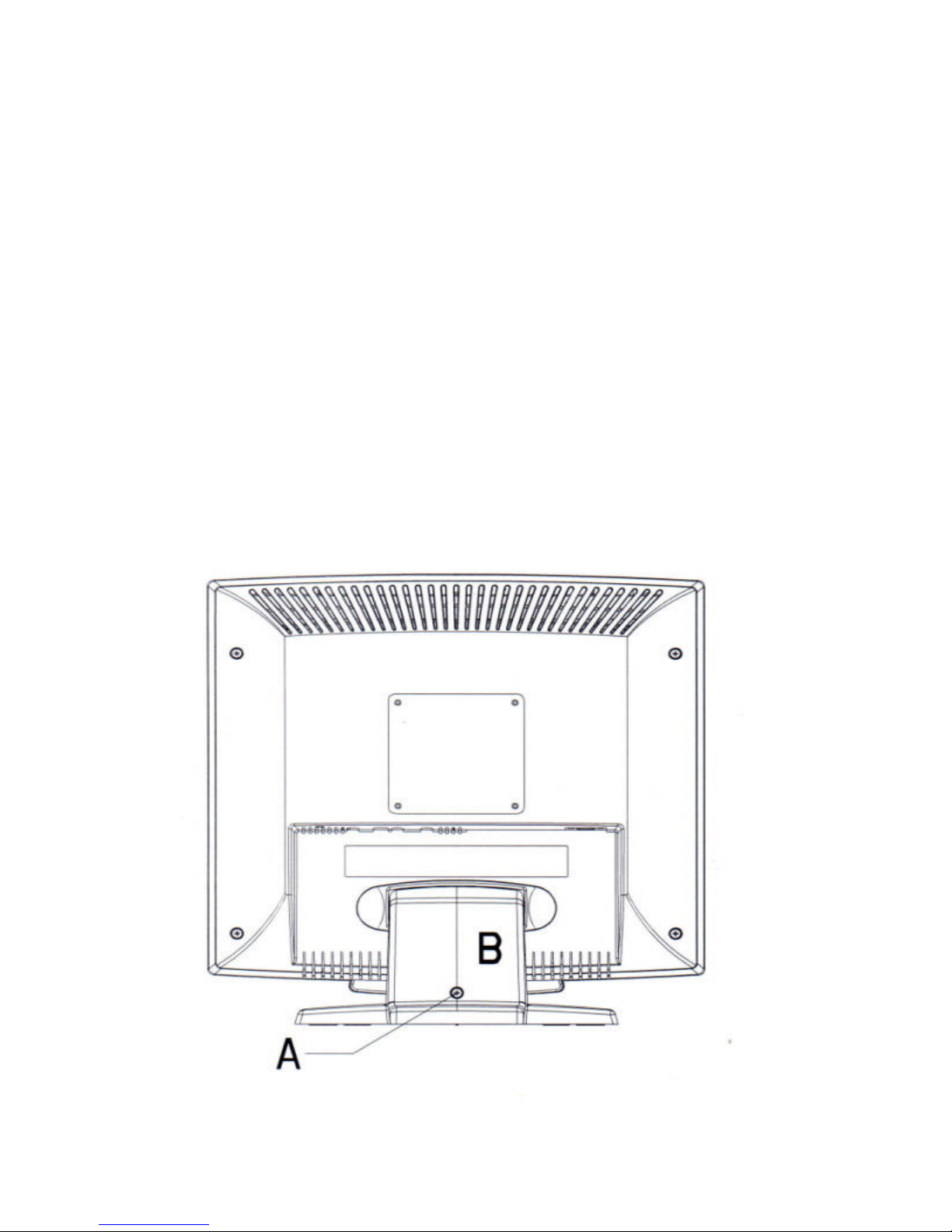
1) Face Down the Monitor.
Note: Face down the monitor on a smooth plane with a soft material on that plane to
protect the panel faceplate.
2) Hinge Cover Removal
As below, remove the screw indicated by “A” from the hinge cover, and then remove the
hinge cover (indicated by “B”) for the base.
Page 7
L7C SERIES LCD Monitor Service Manual (v1.0)
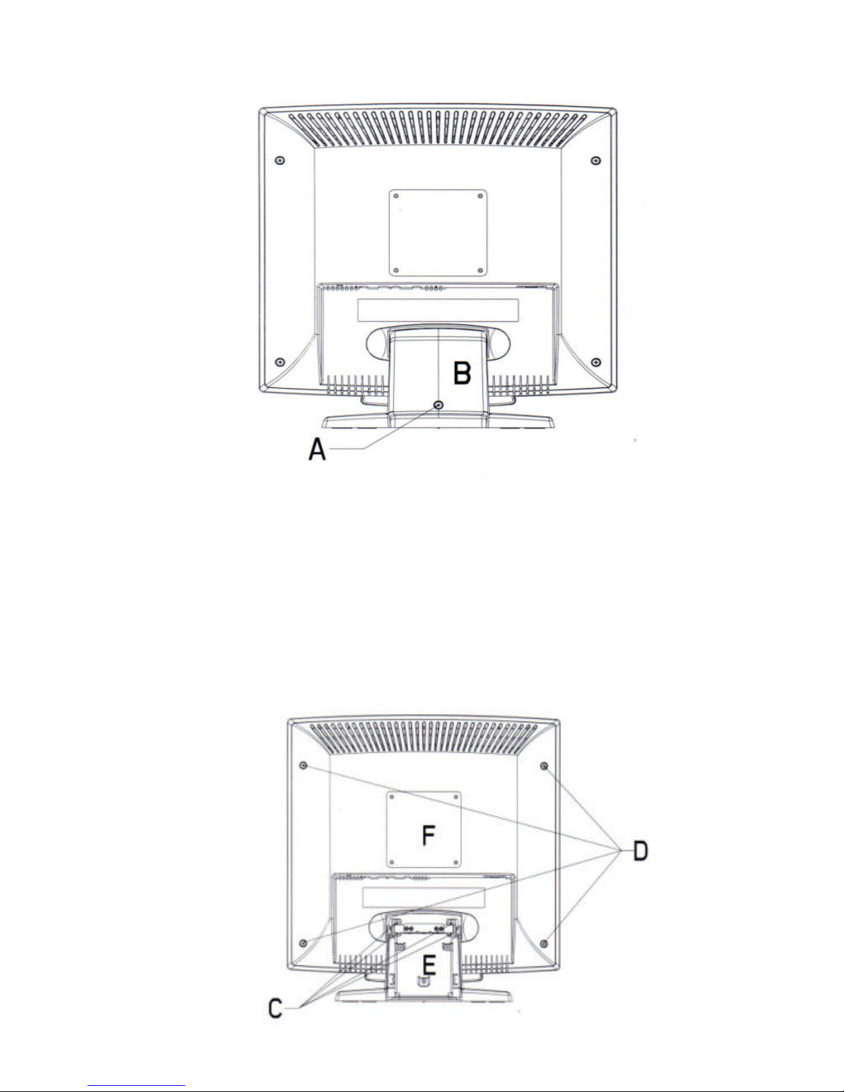
3) Base and Back Cover Removal:
As below, after removing the hinge cover, there will be 4 screws (indicated by “C”), and
remove them. Then you can remove the whole base of the monitor.
Remove 4 screws indicated as “D” of the back cover. Then remove the back cover with
care .
Page 8

L7C SERIES LCD Monitor Service Manual (v1.0)
4) Metallic Cover Removal:
Remove 6 screws indicated as “G” from the back metallic cover. Then remove the back
metallic cover.
5) PCB Assembly Removal:
Caution: When serving or replacing the panel, disconnect the DC power jack completely.
(a) Unplug all connected wires from the PCB.
(b) Remove 3 screws indicated as “K” from the inverter board, and then remove the board
carefully.
(c) Remove 2 screws indicated as “J” from the audio board, and then remove the board
carefully.
(d) Remove 7 screws indicated as “I” from the main board connected with front cover.
Page 9

L7C SERIES LCD Monitor Service Manual (v1.0)
5. General Connection and Applications
Procedures for installing and using this CML171SX LCD monitor are described as
below.
5.1 Connecting the monitor to the computer
1) Place the display on a flat, sturdy surface. Choose an area free from excessive heat,
moisture, and sunlight. Avoid possible sources of electromagnetic interference, such as
transformers, motors, and fluorescent lighting.
2) Locate the AC power adapter with attached power cable and then connect the power cable
to the power jack on the back of the display. Plug the three-prong power cord into a power
outlet, and plug the other end into the AC power adapter. The three-prong power cord is a
shielded type and is provided as a safety precautions to ensure proper electrical grounding.
Plug the D-SUB 15-pin analog signal cable into the Analog Input port on the back of the
display. Connect the other end of the signal cable into your computer’s VGA output port. The
assignment of the pins of the connector is as follows:
Pin Assignment of 15-pin D-SUB connector
1
Red Video
9
+5V for DDC circuit
2
Green Video
10
Logic Ground
3
Blue Video
11
Monitor Ground
4
Monitor Ground
12
DDC-Serial Data
5
DDC-Return
13
H-Sync.
6
Red Ground
14
V-Sync.
7
Green Ground
15
DDC-Serial Clock
8
Blue Ground
Page 10

L7C SERIES LCD Monitor Service Manual (v1.0)
3) First turn the PC power switch ON. Then apply power to the display by pressing the power
button to turn the monitor on. The power indicator LED will then illuminate.
Note: Do not force the cable into the connector; line it up carefully so that you don ’t
bend the pins.
Page 11

6. Electronic Block Diagram
RED
GREEN
BLUE
H_SYNC
V_SYNC
SCL
SDA
3.3V
12V
5V
Audio in
ANALOG R.G.B INPUT
24WC02
(DDC2B)
gmZAN1
PLL
ADC
OSD
SCALER
160 pin PQFP Package
LVDS
MICROCONTROLLER
Regulat
LVDS
TFT LCD PANEL
Audio Ampilier
Speaker/Earphone
INVERTER
Page 12

Troubleshooting Flow Chart
No
No
YES
No
No
YES
YES
YES
YES
YES
NoNo
YES
No
No image appear
LED light up
Voltage
of P006
pin 1 is
5V
Replace
PWB-0319
Voltage
of C305
is 5V
Replace
PWB-0265
Is the
frequency
of R005
20 MHz
Replace
X001
Replace
MCU
I003
LED display
is amber
Is it entering
power Saving
Restart PC
signal to ensure
H.V Sync. are
not absent
End
LED
display
is
Green
Replace
MCU
I003
Replace
INVERTER
Replace
PWB-0265
Page 13

Page 14

Page 15

Page 16

Page 17

Page 18

Page 19

Page 20

Page 21

Page 22

APPENDIX F.
Service parts
Description Part Number
WIRE ASS'Y SIGNAL CABLE
5057415162
AC/DC ADAPTOR
5061369403
PPOWER CORD,Europe
5056705939
POWER CORD,UK
5056705992
WIRE ASS'Y W/05P CONN.
5057405110
Inverter Assembly
5000100023
ASSEMBLY,PCB-MAIN
5097699603
ASSEMBLY,PCB-AUDIO BOARD
5097699704
ASSEMBLY,PCB-KEY BOARD
5097699803
QUICK TIE,PVC
5071000510
AUDIO SIGNAL CABLE
5057402323
Microphone Wire Ass'y
5055120001
WIRE ASS'Y 6PIN CONNECTOR
5057406127
WIRE ASS'Y 30PIN CONNECTOR
5057430002
Speaker Box Ass'y
5055120200
MODEL LABEL
5030434421
USER'S MANUAL
5030034701
BRACKET-LCD
5642720700
BRACKET SMIELD
5646248800
SCREW,PRWS M3.0x06 S-ZN-Cc
7136160652
SCREW ISO PPW M3.0X06 S-ZN-CC
7000311032
TAPE OF AL FOIL
5648006502
SCREW ISO PPW M3.0X10 S-ZN-CC
7000311042
BASE #31455 5642283002
SCREW BFB M4.0X08 S-ZN-CC
7034251152
NECK-F #31455
5642282802
SCREW,PZP M4.0X10
7134251482
SCREW ISO PP M4.0X06 S-ZN-CC
7001260612
NECK-B #31455
5642282902
SCREW,PZS M4.0x08 S-PC
7134251156
NECK BRACKET
5642721200
RUBBER FOOT
5642025400
HINGE-L
5642721400
SCREW MS CROSS PANHEAD SW
7190030022
HINGE-R
5642721500
SCREW MS CROSS PANHEAD SW
7190030022
FRONT COVER(TATUNG)#31455
5642282600
SCREW,PZP M4.0X10
7134251482
FRONT PANEL #31455
5642381702
BUTTON-4KEY #31455
5642842900
SCREW,PZP M4.0X10
7134251482
VISA MOUNT BRACKET
5642721300
SCREW,PZP M4.0X10
7134251482
BACK COVER #31455
5642282702
SCREW,PZS M4.0x08 S-PC
7134251156
SCREW,PZS M4.0x10 ZN-BLK
7134251456
DECORTING PLATE (#31455)
5642417203
RS CARTON L7CMS (NATURAL) 9513050156
EPS PAD-L L7CM
9523050156
EPS PAD-R L7CM
9523050256
PE BAG
9533020256
TCO99 LOGO 5635582100
TCO 99 LABEL 紙箱 5635578602
 Loading...