

Page 1
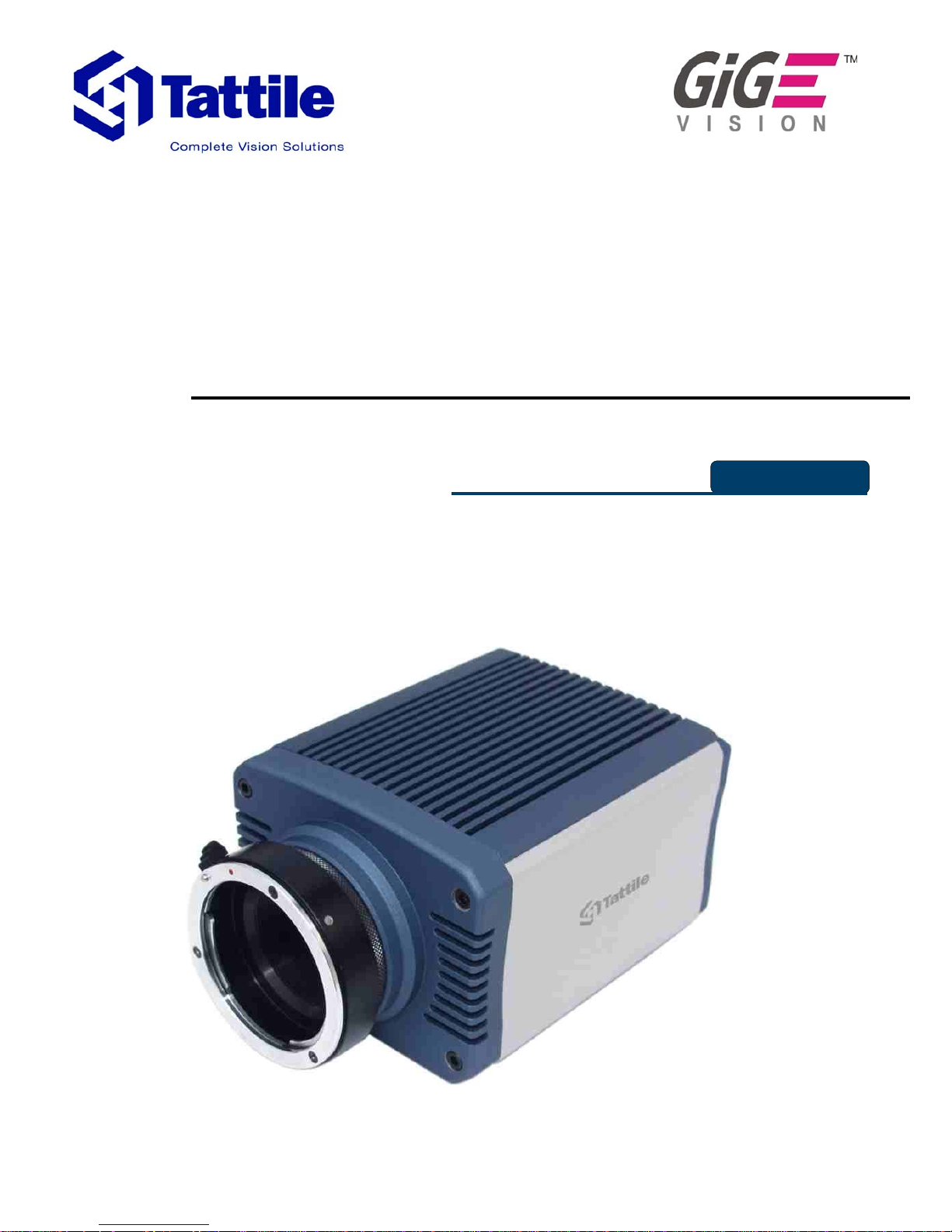
TAG-2 CAMERA
quadri-linear
Reference Manual
© 2005 by TATTILE S.r.l.
ENG
Page 2

Version__03.00.00 (November 2005)
© 2005 by TATTILE S.r.l.
The Gige® logo is registered mark of the Automated Imaging Association.
All Tattile's systems were created to be alive, smart and open products. Therefore, we give you the chance to
update features and capabilities during the whole life cyc le of the produc ts.The Download area of our web site has
been created to allow our Partners to download new releases of Firmware and Software: http://www.tattile.com
.
All material in this publication is subject to change without notice and is copyright Tattile S.r.l.
Page 3

Index
Mechanical Dimensions.....................................................................................................................4
Connectors and Indicators.................................................................................................................5
General Characteristics.....................................................................................................................6
CCD General Characteristics.............................................................................................................7
Interface Connection..........................................................................................................................9
Example of Connection....................................................................................................................12
Instructions for a right installation of TATTILE control equipment...................................................14
Warning!..........................................................................................................................................15
Revisions.........................................................................................................................................16
3
Page 4
TAG-2 CAMERA
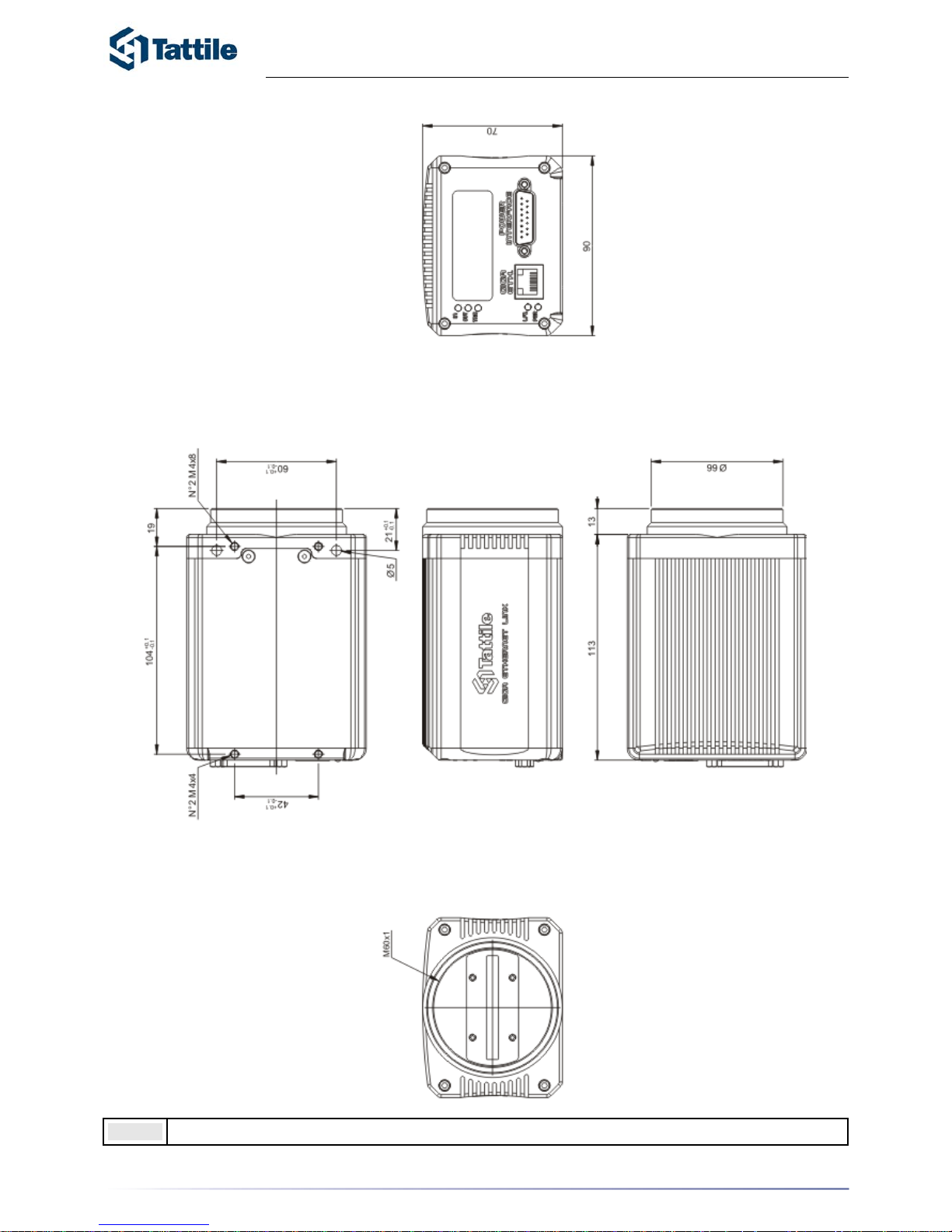
Mechanical Dimensions
Note: To fix use only M4 screws, appling 1,55 Nm force.
4
Page 5
TAG-2 CAMERA
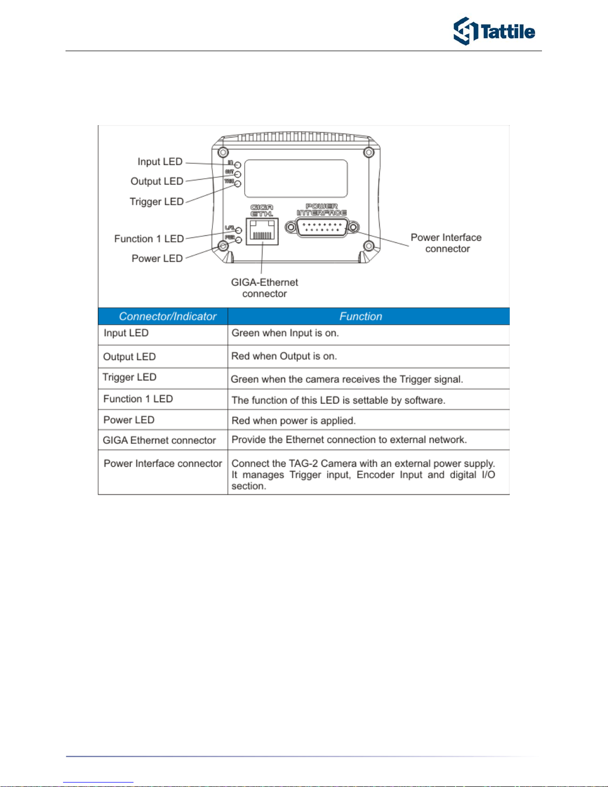
Connectors and Indicators
Rear View
5
Page 6
TAG-2 CAMERA
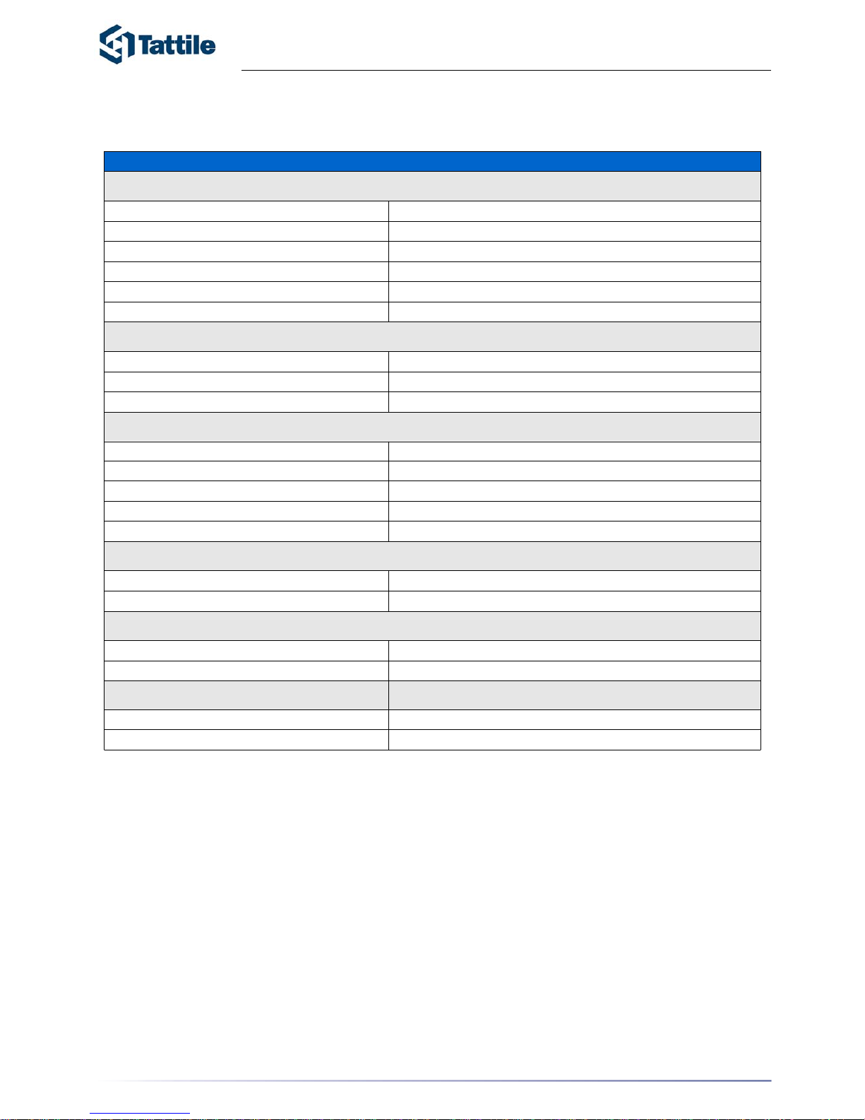
General Characteristics
6
+24V
9 W
Processor:
Flash
SDRAM Micro
IP42
TAG-2 C amera
0V
0°C +50°C
-10°C +65°C
Characteristics
Electric Char acter istics
Power Supply
Power Cons umpt ion
Sensor Linear CCD sensor
Digital Inputs 2 optois olated inputs 24V dc 20m A
Digital Outputs 2 PNP optoi so l ated outputs 24Vdc 500mA
Ethernet Net work GigaE thernet 10 bit
Microprocessor Al tera NIOS F P G A Technology
8 Mb Fl ash M emory
32 Mb
Mechani cal Ch aracter istics:
Mechanical Dim ensions 113 x 90 x70 m m (LxHxW)
W ei ght 900 gr (wit hout l ens)
Package B ody Anodi zed Al um inium
Protection Degree
Conformity Conform to CE Standards
Standard Supply
Reference Manual
Work Tensions
Suppl y voltage +24 V . Provide a stable suppl y +/- 10% .
Ground
Operating Condition
Operat i ng Temperat ure
Storage Temperat ure
Page 7

TAG-2 CAMERA
CCD General Characteristics
CCD Specifications
7
Pa ra met ers Value
Total Number of Pixe ls
3x4134 c hrom a
1x8292 lum a
Number of Effective Pixels
3x4128 c hrom a
1x8276 lum a
Number of Active Pixels
3x4080 chroma
1x8160 lum a
Pixel Siz e 10 µm (H) x 10 µm (V)
chroma 5 µm (H) x 5 µm (V ) luma
Pixel Pitch
10 µm c h rom a
5 µm lum a
I n t er-Ar r ay S pac in g G to R R to B 90 µm (9 l ines effecti ve)
B to L 122.5 µm (12. 25 lines effective)
Chip Size 50.5 mm (H) x 1.1 mm (V)
Satur atio n Si g nal
132000 electrons chroma
100000 electrons luma
Quantum Efficiency (B) 62%(B )
Quantum Efficiency (G) 62%(G)
Quantum Efficiency (R) 80%(R)
Quantum Efficiency (L) 85%(L)
Output Sensitivity
Chroma -14 µV/electron
Luma -11 µV/ el ectron
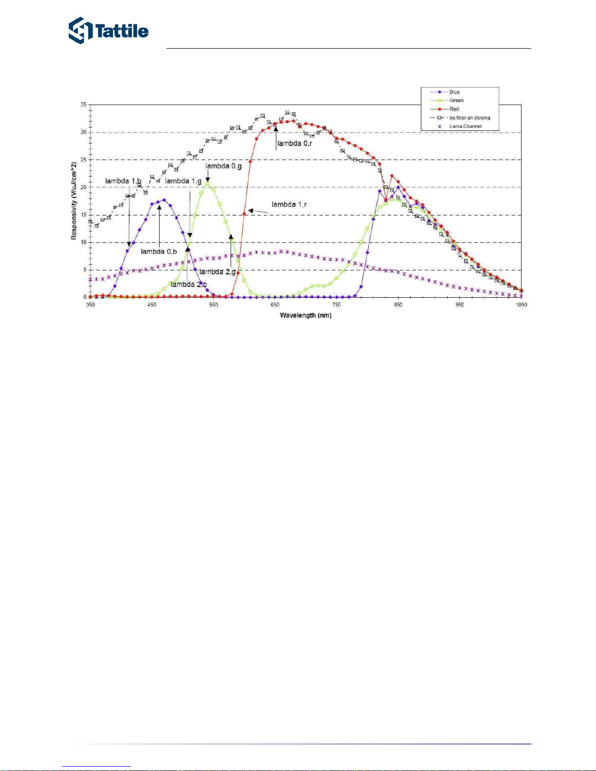
Responsivity ( B) 17(B) V /µJ/ cm2
Responsivity ( G ) 20(G) V/µJ/cm2
Responsivi ty (R) 32(R) V/ µJ/cm 2
Responsivity ( L) 27(L) V/ µJ/cm 2
Total Read Noise 120 elec trons
Dark Current
Chroma 0. 007 pA/ pixel
Luma 0.0008 pA/ pixel
Dark Current Doubling Tempera ture 9ºC
Dynamic Ran ge @ 30 MHz Data Rat e
60 dB (c hrom a)
60 dB (lum a)
Photoresponse Non-uniformity 5% Peak-P eak
Charge Transfer Efficiency 0.99999/Transfer
Max imum Data Rate 30 Mhz/Channel
Exposure Control
Gain
0:1023
Offs et 0:255
Pow er Suppl y 24 V
Consumption 5W
>31µs
Page 8
TAG-2 CAMERA
Picture 1 - Sensor Typical Responsivity
8
Page 9
TAG-2 CAMERA
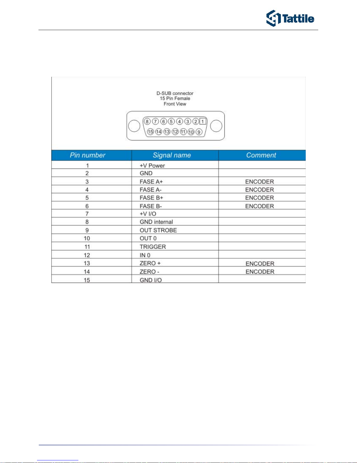
Interface Connection
Power Interace connector
9
Page 10
TAG-2 CAMERA
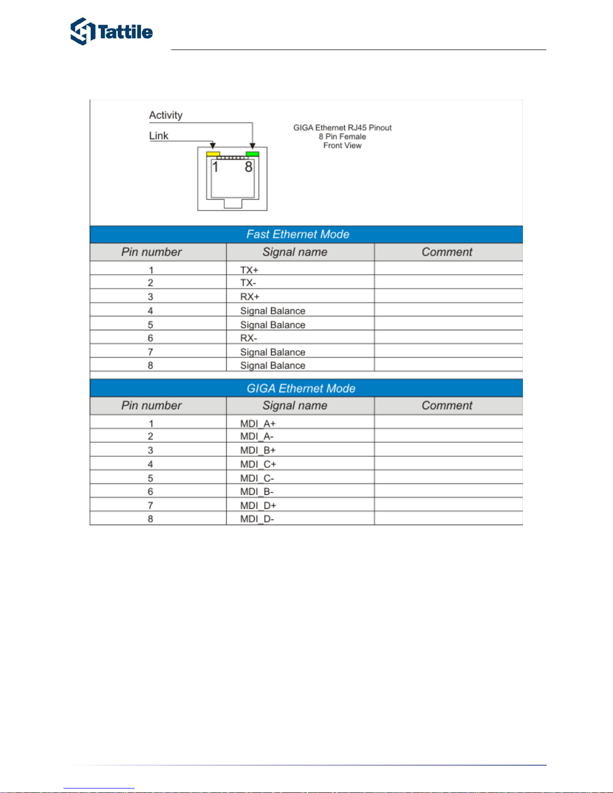
Ethernet Connector
10
Page 11
TAG-2 CAMERA
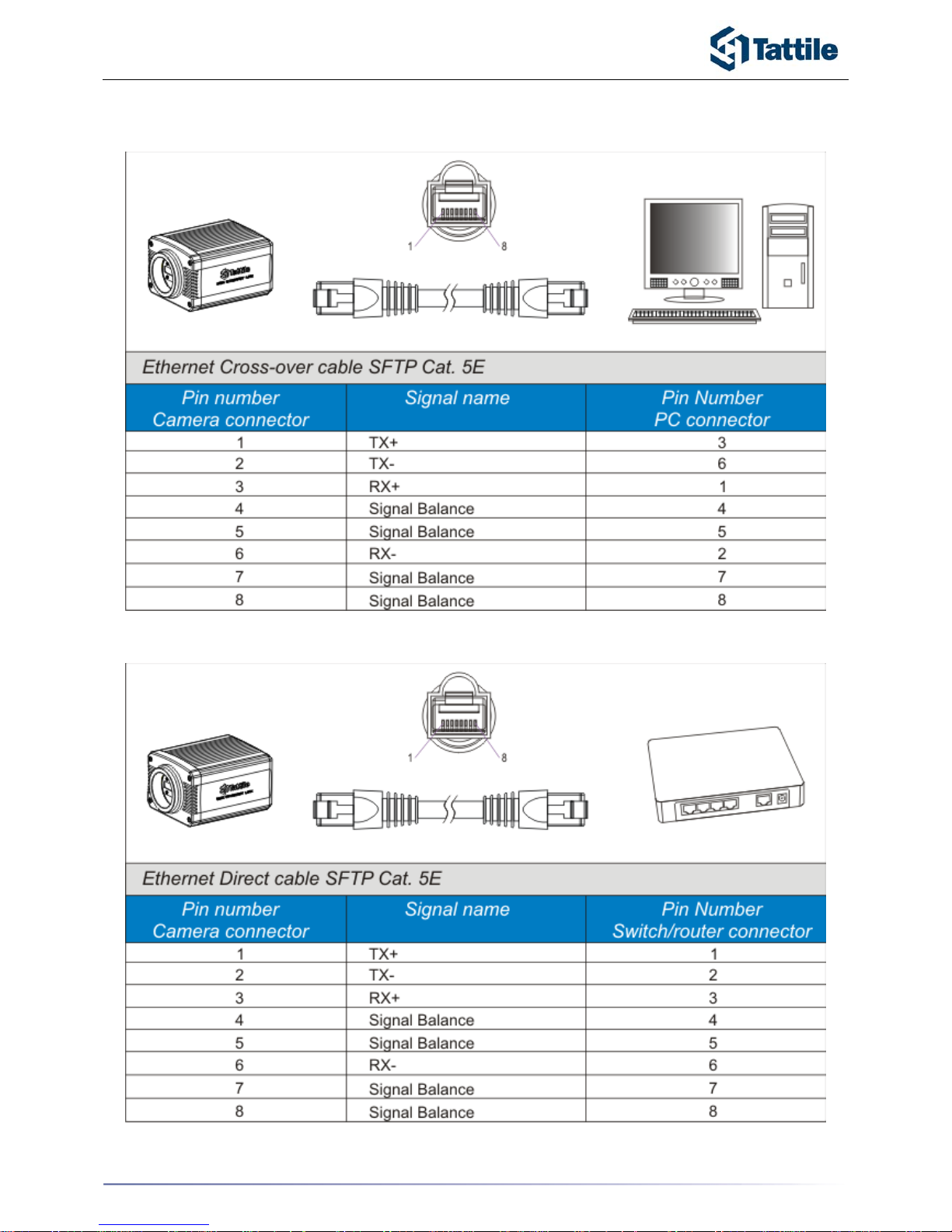
Ethernet Connection Cables
11
Page 12
TAG-2 CAMERA
Example of Connection
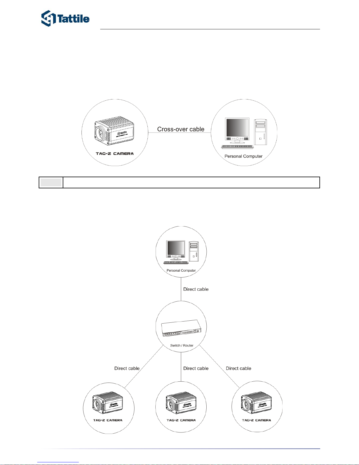
Standalone Connection
The TAG-2 CAMERA can be connecte d directly to a PC using an Ethernet cross-over cable.
The operator uses the PC to configure applications and monitor runtime operation. In this
configuration, th e camera is isolated from the factory network.
Note:
For connection between TAG-2 CAMERA M0 and PC use a cross-over cable.
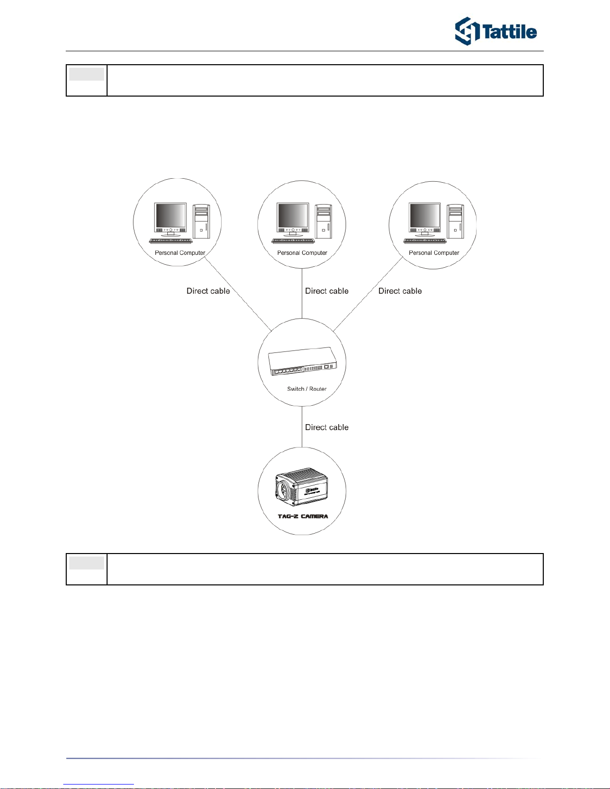
Connection using Switches/Routers
A maximum of 4 TAG-2 CAMERA can be conn ected to a personal computer, by using a
network router or an ethernet switch.
12
Page 13
TAG-2 CAMERA
Note:
For connection between PC and switch/router and between switch/router and TAG-2
CAMERA use ethernet direct cables.
The TAG-2 CAMERA can be connected to a network fa ctory, by using a network r outer or an
ethernet switch.
Note:
For connection between PC and switch/router and between switch/router and Smart
Reader M0 use ethernet direct cables.
13
Page 14

TAG-2 CAMERA
Instructions for a right installation of TATTILE control equipment
Good equipment operation is guaranteed only by respecting the instructions cited in this refer ence manual.
TATTILE declines all responsibility for anomalous equipment operation, installed with criteria
not respecting these instructions.
• TAG-2 CAMERA cable courses must be kept separate from power cables.
• Pay attention to the various connections, especially in respect to the correct
polarity of the power-supply cables.
• Supply the TAG-2 CAMERA with a dedicated power-supply.
• The power supply for inputs and outputs must never be taken from the same
power source of TAG-2 CAMERA. The mass hasn't to be linked.
• The power supply cable must be screened and not longer than necessary.
14
Page 15

TAG-2 CAMERA
Warning!
The warranty covering TATTILE equipment is invalidated when :
1. The equipment has been opened or tampered with.
2. Faults due to incorrect connection of power or input/output circuits.
3. Faults due to overload or non-compliance with equipment's rated specifications.
4. Application act in conditions that do not comply with those specified for a correct
installation.
Note:
These conditions concern all equipment supplied with the system.
15
Page 16

TAG-2 CAMERA
Revisions
The Revision Index is reported below. The various revisions can contain additional
information or corrections of printin g errors.
Rev. Date Page Description Prepared Checked Approved
03.00.00
December
2005
All First release Nicola G. G.Gualeni Nicola F.
16
 Loading...