

Page 1
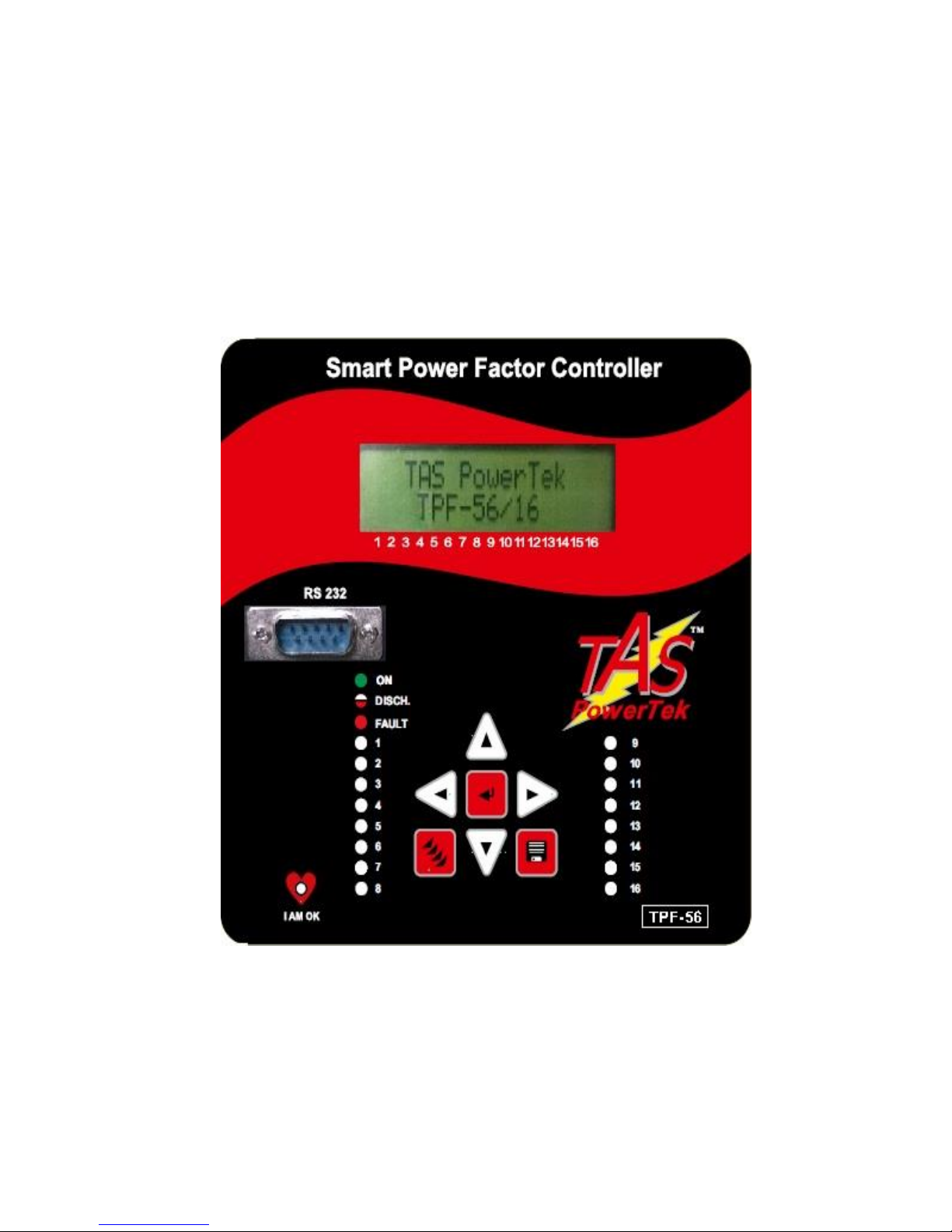
LT Intelligent Automatic Power Factor Controller
& Data Logger
For Capacitor-Duty Thyristor Switches,
For High-Speed Power Factor Correction
TPF-56
User Manual
Version 1.1.5
Updated on: 22
nd
March 2016.
Page 2

NOTE
These instructions do not purport to cover all details or
variations in equipment, nor to provide for every possible
contingency to be met in connection with installation,
operation or maintenance.
Should further information be desired or should particular
problems arise which are not covered sufficiently for the
purchasers purposes, the matter should be referred to our
office.
The contents of this instruction Manual shall not become
part of or modify any prior or existing agreement or
relationship. Any statements contained herein do not create
new warranties or modify the existing warranty.
The reproduction, transmission or use of this
document or its contents is not permitted
without express written authority. Offenders
will be liable for damages. All rights are
reserved.
Intelligent Power Factor Controller TPF-56
CAUTIONS:
1. There are High Voltages associated with this Unit. So, take appropriate
precautions.
2. To be installed & commissioned by a technically qualified person only.
3. Make sure that the discharge time set in the controller matches
the capacitor discharge time!
4. This Automatic Power Factor Controller (APFC), TPF-56, is to be used
indoor only.
5. Make sure that the Capacitor Bank Discharge Time set in the PF
Controller matches with the actual Capacitor Bank Discharge Time.
6. This User Manual is applicable to TPF-56 Unit with Firmware
Version 1.0.7 as on 25 JAN, 2016.
Because of continuous improvements carried out by TAS PowerTek in their
Product’s Features and Specifications, the Product as well as the Content of the User
Manual is likely to get updated without any prior notice.
Therefore, please always refer to the User Manual supplied to customer along with
the Product, at the time of product dispatch.
!
2 of 56 Version 1.1.5 22nd March, 2016
Page 3

Index
Section Page No.
Index page -- 3
Ordering Information -- 4
Features -- 5
Specifications -- 8
Functional block diagram -- 15
PF correction technique -- 16
Typical wiring scheme -- 18
Front fascia -- 19
LCD display contrast & backlit -- 22
Display of various parameters -- 23
Sub menu for display of parameters -- 24
Method of Keyboard / Display usage -- 26
Keyboard / Display operations -- 29
Edit Parameters -- 30
General & I/O -- 31
System -- 31
Fault -- 32
Steps -- 35
Communication -- 36
Utilization counter -- 37
Notes On Protection
and Functionalities -- 38
Fault indications and
Fault actions -- 40
Data logging facilities -- 41
Power-fail monitoring -- 42
Commissioning Instructions -- 43
Fault finding Guidelines and
Trouble shooting procedures -- 45
Factory Default Settings -- 47
Maintenance Copy
(Blank Forms for User) -- 52
Manufacturer’s Contact Details -- 56
Intelligent Power Factor Controller TPF-56
3 of 56 Version 1.1.5 22nd March, 2016
Page 4

Ordering Information
Product Specific Information Number (PSIN)
TPF-56 / nn
nn: Number of Current-sourcing, 20 milli-Amps Current-Limiting, Transistor
Output stages: 04,08, 12, or 16.
Please specify the “nn” while quoting, ordering, buying etc.
Note that the Isolated +12 V DC Supply is from User Side, and the “Return” for
all Command Outputs of TPF-56/nn are “Commoned” to 0 V of the +12 V DC
Supply, at the TAS Thyristor Switches Side.
The TPF-56 Units with TAS Capacitor-Duty Thyristor Switches make ideal
combinations for Applications in Welding Shops, Reciprocating Piston AirCompressors, Electric Arc Furnaces, Induction Furnaces, Rolling-Mills etc.
Intelligent Power Factor Controller TPF-56
4 of 56 Version 1.1.5 22nd March, 2016
(Similar APFC Unit is available with Potential-Free, Normally-Open (N. O.)
Relay Contacts, as SPF-56, for Medium-Speed, P. F. Corrections, based on ThreePhase, Capacitor-Duty, Power Contactors & Three-Phase, Delta Connected Power
Capacitors, with Discharge Resistor and optional Current-Limiting I de-tuned
Inductive Reactors in EACH Phase to the Power Capacitor.
The SPF-56 Firmware is compatible for the Relays and the Contactors based
Medium-Speed PF Correction Applications with TAS Reactors and Capacitors.
Please contact TAS PowerTek, Nasik, India, for further details.)
Page 5

Features:
• Totally Micro-Controller based logic for measurements, monitoring,
analysis & control.
• Functionality Suitability: LT PF correction application for Distribution
Transformers secondary side used by Electricity Distribution
Companies, Private Industries, Offices, Establishments etc.
• Protection and Functionality to take care of Supply System
abnormalities and various faults.
• Protection against internal faults and its controlled components like
Capacitor Banks and switching thyristor.
• Communication port RS-232 for logged data downloading and for
other convenience functionalities.
• Completely Fire Retardant ABS grade plastic material body with
sufficient ventilation for cooling.
• Externally replaceable battery slot for maintenance convenience. This
battery is used primarily for RTCC – “Real Time Clock-Calendar” to
work during supply power down condition.
• LCD – 16 Char. x 2 Line Yellow-green Backlight and Black Characters,
Display for Display of various parameters, symbols & functionalities
requirement.
• Keypads with soft touch 7 Nos. of keys for Scrolling between various
displays and various functionalities / settings.
• Power supply and measurement range is wide-ranging and highly
reliable operation under various supply system PQ issues like supply
voltage dips / swells, transients, cycle loss etc.
• Reliable Screw type terminals for fork/ring type lugs with externally
replaceable fuse protection for transistor outputs.
• Capacitor Banks – same value Equal Utilization logic.
Intelligent Power Factor Controller TPF-56
5 of 56 Version 1.1.5 22nd March, 2016
Page 6

Features (Continued):
• Capacitor Banks actual value measurement in terms of KVAr (reactive
power) normalized values for rated supply voltage and frequency, for
monitoring it’s health. This is on-line monitoring with complex
algorithm for getting right values under variable loading conditions
authentically.
• Measurement and Display of Various Electrical values:
3-phase Voltages (Line – Neutral Values)
3-phase Currents and Neutral Current.
Individual Phase PF, Active Power, Reactive Power, Apparent
Power values.
AC Mains Supply Line frequency.
Overall Values: Average Voltage & Current, Total Active Power,
Total Reactive Power, Total Apparent Power.
Energy Values: Active Energy Consumed, Reactive Energy
Inductive (uncompensated), Reactive Energy Capacitive
(uncompensated), Apparent Energy.
Harmonics: Per Phase V-THD-F% and I-THD-F% values up to 15th
odd harmonics.
Capacitor Bank Values: Normalized for rated supply voltage and
frequency and monitored on line.
Temperature of the Unit.
Battery Voltage for RTCC / NV-RAM Battery.
• Data Logging: Unit has sufficient Non-Volatile memory to log hourly,
30min,15min,10min readings and to log last 1024 events. The
Parameters are logged for downloading on PC based program “Data
View” for viewing and report generation purpose.
The Logged values for viewing and report generation are:
Unit ID, Sr. No., Date / Time stamp.
3-phase Voltages (Line – Neutral Values)
3-phase Currents.
Supply frequency.
Overall Power Values: Total Active Power, total Reactive Power,
total Apparent Power.
Energy Values: Active Energy Consumed, Reactive Energy
Inductive (uncompensated), Reactive Energy Capacitive
(uncompensated), Apparent Energy.
Harmonics: Maximum value of Phase V-THD-F% and I-THD-F%
values.
Intelligent Power Factor Controller TPF-56
6 of 56 Version 1.1.5 22nd March, 2016
Page 7

Features (Continued):
Capacitor Bank Values: Normalized for rated supply voltage and
frequency and monitored on line.
All Capacitor Bank Status.
Temperature of the TPF-56 Unit.
Battery Voltage for RTCC / NV-RAM Battery.
• Data Mobilizer – In future, we will add Hand Held Unit (HHU-01) as a separate
unit, that can be procured separately for transfer of data from remote site
located TPF-56 Unit that can be further uploaded to PC having “Data View”
software. Such Unit even have added facilities like fixed set parameter
uploading (5 pre-programmed sets of Parameters to be programmed in TPF-
56).
• Manual Mode (Testing) facility available for convenience of checking the TurnOn and Turn-Off of capacitor banks. This feature is additionally useful for
Manual Synchronization and for resetting the “faulty” declared capacitor banks.
• GSM (global system for mobile) :
Enabling GSM send SMS about various parameter :
3-phase Voltages (Line – Neutral Values)
3-phase Currents and Neutral Current.
Bank status .
Fault.
• RS485 communication :
There are two basic transmission modes found in serial MOD-BUS
connections, ASCII and RTU. These transmission modes determine the
way in which the MOD-BUS messages are coded.
One of the main differences between MOD-BUS/ ASCII and MOD-BUS RTU
is that ASCII allows gaps between the bytes of a message with a
maximum length of 1 second. With MOD-BUS RTU, continuous streams of
messages must be sent. Enabling Modbus ASCII or RTU gives values:
3-phase Voltages (Line – Neutral Values)
3-phase Currents and Neutral Current.
Individual Phase PF, Active Power, Reactive Power, Apparent Power values.
AC Mains Supply Line frequency.
Overall Values: Average Voltage & Current, Total Active Power, Total
Reactive Power, Total Apparent Power.
Energy Values: Active Energy Consumed, Reactive Energy Inductive
(uncompensated), Reactive Energy Capacitive (uncompensated),
Apparent Energy.
Harmonics: Per Phase V-THD-F% and I-THD-F% values.
Capacitor Bank Values: Normalized for rated supply voltage and
frequency and monitored on line.
Temperature of the Unit.
Intelligent Power Factor Controller TPF-56
7 of 56 Version 1.1.5 22nd March, 2016
Page 8

Specifications of TPF-56/xx Unit:
1. Rated supply values:
3 – Phase, 4 – Wire supply system.
Line-to-Line rated voltage 440VAC sinusoidal.
Rated frequency 50Hz(+/-3Hz) Or 60Hz(+/-3Hz)
2. Auxiliary Supply:
Line to Line sinusoidal voltage range 100VAC - 500VAC.
Supply frequency range 47 Hz to 63 Hz.
Supply VA burden – 8 VA maximum. (typical 6 VA)
Protected by externally replaceable 0.8 A/500VAC slow-blow
glass type standard fuse.
3. Metering (measurement) Input:
Voltage Input:
Voltage 3-Ph, 4-Wire with Ph-N values range of measurement
as 60 VAC to 300VAC.
Voltage Measurement burden < 1VA per phase.
Current Input:
Current measurement through secondary current of 3 Nos of
Current transformers with secondary rated current as either
1Amp or 5Amp AC.
Current measurement range: 1.5%I
Nominal
to 130%I
Nominal
For 1Amp terminals: 15mA to 1.3Amp.
For 5Amp terminals: 75mA to 6.5Amp.
Maximum current withstanding capacity: 4xI
Nominal
for 1 Second.
Maximum VA burden on CT: < 1VA.
Measurement Values and Accuracy:
Per phase Voltage, Per phase & neutral Current,
Overall Power and Overall Energy values with accuracy class
1.0 as defined in IS-14697 with all Amendments till date.
This is for Active & Reactive Power / Energy.
Intelligent Power Factor Controller TPF-56
8 of 56 Version 1.1.5 22nd March, 2016
Page 9

Specifications (continued):
5. Transistorized Output:
Total No. of Transistorized Output for capacitor banks
switching ON / OFF : Maximum up to 16 Numbers.
Voltage & Current Rating, Transistorized O/Ps (Short-Circuit Protected) :
+12 VDC to +24 VDC, Current-Sourcing Output, 20 mA max.
Protected by Glass cartridge fuse – 200mA,+12/24V DC/fast blow.
6. Connection Terminals (rear side):
All the connectors are on rear side and suitable for connecting
fork type copper lugs with 1.5mm2 or 2.5mm2 wires.
Maximum applicable torque on Screws of Terminal while
tightening is 0.5 Newton-meter. Recommended torque
calibrated screw driver adjustment is 0.35 N-met.
Voltage rating across 2 adjacent terminals – 380VAC.
Continuous Current rating (RMS value) – 8 Amp.
7. Battery for RTCC (Real Time Clock-Calendar) & NV RAM:
Battery type to be used : CR2032. (Maxell make preferred)
Battery Voltage (New) : 3.3VDC to 3.1VDC.
Low Battery Alarm : 2.6VDC. (Range 2.65VDC to 2.55VDC)
Battery Fault Indication : < 1.8 VDC.
Expected Battery Life: @ 2½ Years to 3 Years.
Time frame for Battery replacement after Low Battery Alarm
is Maximum 6 months. Recommended period < 3months.
8. Data Log Non-Volatile Memory:
Used for TPF-56 Program Parameter storage, 1 Hour, 30min,15min,10min
interval data log, latest 1024 events data log and Power-down values
storage with “Early-Warning-Power-Failed (EWPF)” sequence.
Critical storage even with RTCC Battery Fail or Replacement for
ensuring no data loss or maintain Energy values.
Intelligent Power Factor Controller TPF-56
9 of 56 Version 1.1.5 22nd March, 2016
Page 10
Specifications (continued):
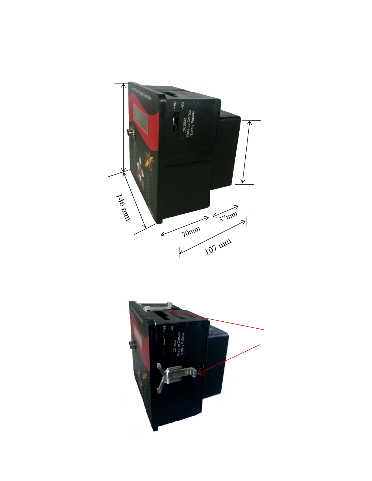
9. Mechanical Dimensions:
Intelligent Power Factor Controller TPF-56
Mounting
Clamps
All 4 sides.
10 of 56 Version 1.1.5 22nd March, 2016
All Dimensions in mm.
146 mm
95 mm
•Un-packed net weight of the Unit: 880 gm.
Page 11
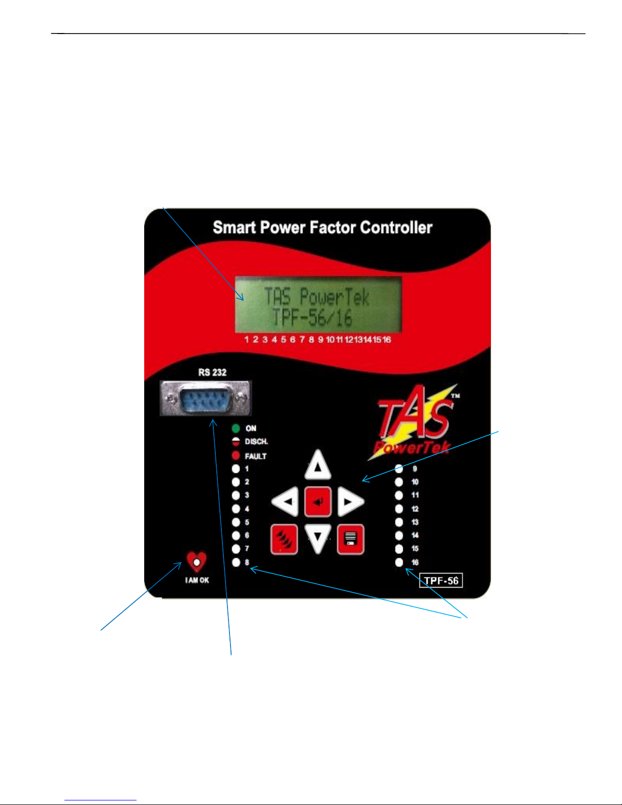
Front fascia
LCD Display
RS-232 port with
dedicated protocol.
Key pad
I AM OK LED
(Controller
“Health”
status LED)
Intelligent Power Factor Controller TPF-56
Specifications (continued):
11 of 56 Version 1.1.5 22nd March, 2016
Leds for indication
of status of
Capacitor Banks
Page 12
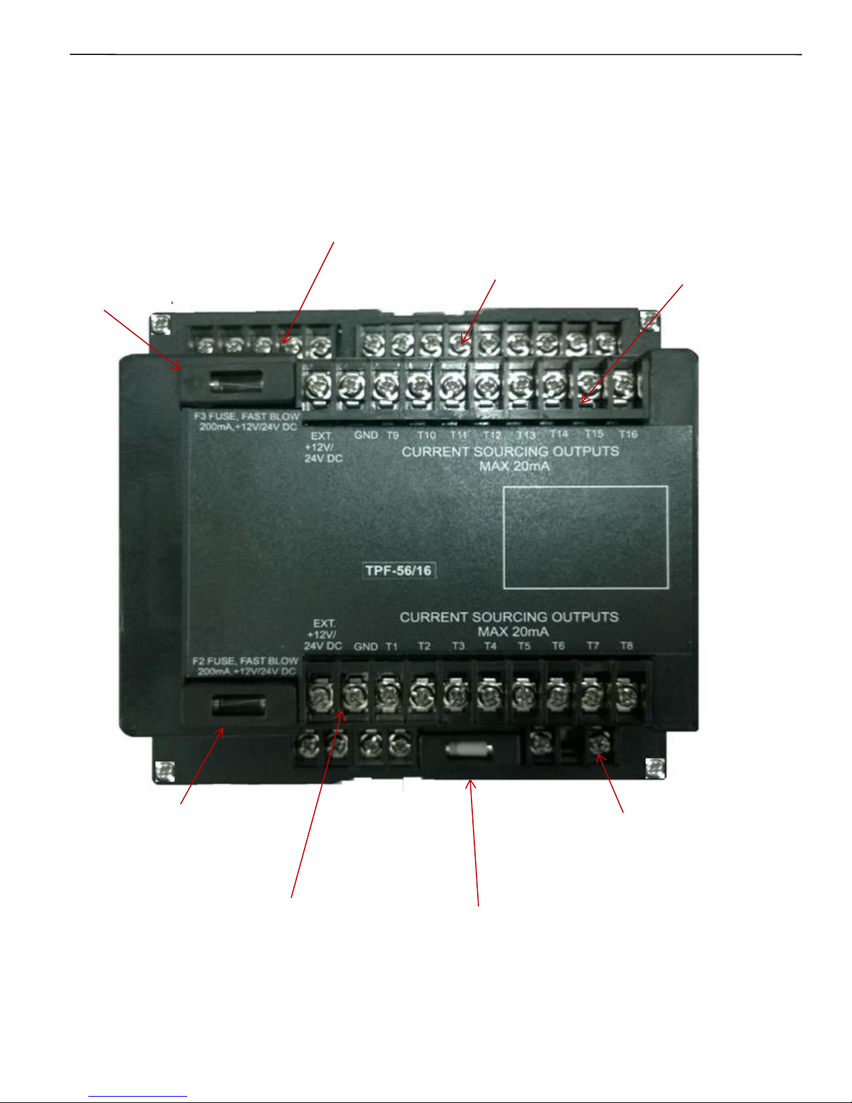
Back side terminals
Note:
Use appropriately rated and type, while replacing the fuse(s) in the field
Measurement voltage
(Line To Neutral 300VAC max)
Auxiliary Supply
Voltage
(100V to 500 VAC)
Load current CTs
F1: Fuse for Auxiliary
Supply ( 0.8 A/500 VAC
slow-blow glass
Cartridge.)
Intelligent Power Factor Controller TPF-56
Specifications (continued):
12 of 56 Version 1.1.5 22nd March, 2016
F2: Fuse for Capacitor
Banks 1 to 8
(200mA,+12/24 VDC
Fast- blow,
Glass Cartridge).
Output commands
to Thyristor switch
1 to 8 Outputs.
F3: Fuse for Capacitor
Banks 9 to 16
(200mA,+12/24 VDC
Fast- blow,
Glass Cartridge).
Output commands
to Thyristor switch
9 to 16 Outputs.
Page 13
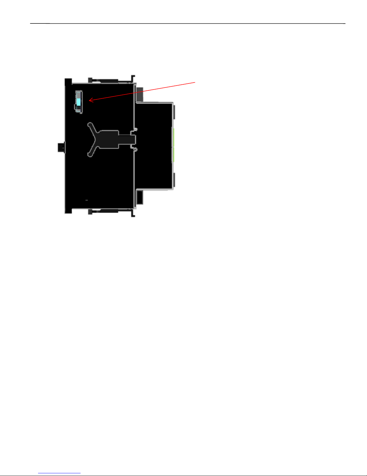
Other Auxiliary Arrangements:
RTCC Battery insertion slot.
Intelligent Power Factor Controller TPF-56
Battery Slot for replacement
Of CR2032, 3 Vdc Li. Battery.
(Remove black sticker over the slot
to see the battery inside)
Recommended to change the Battery
with Auxiliary Supply to Unit in ON
condition. RTCC would not be disturbed.
Ensure new battery replacement with
Correct polarity. Use tips insulated, thin
& long nose plier to remove old battery
& insert the new battery.
In case the Aux. Supply was OFF and then
this RTCC Battery is replaced, user will
have to set RTCC once again to correct
date & time.
- +
Side view of TPF-56 for seeing Battery insertion slot.
The unit after mounting in panel is compatible for
enclosure protection class as per DIN 40 050:
Front side: IP-54.
Back side: IP-10.
Specifications (continued):
10. Environmental Requirements:
Operating temperature range: 0°C to +55°C.
Storage temperature range: 0°C to +65°C.
Altitude: up to 3500 meters above sea level.
Relative Humidity range: 10% to 95% RH (Non-condensing).
11. Standards Compatibility:
Unit is designed to comply with following standards compliance.
Safety Standards: IEC61010-1:2001
EMI Standards: CISPR 11
EMC Standards: IEC61000-4-2:8kV
IEC61000-4-4:4kV
IEC61000-4-11:Class A.
Accuracy Standards: IS14697: Class 1.0
13 of 56 Version 1.1.5 22nd March, 2016
Page 14
Intelligent Power Factor Controller TPF-56
Specifications (continued):
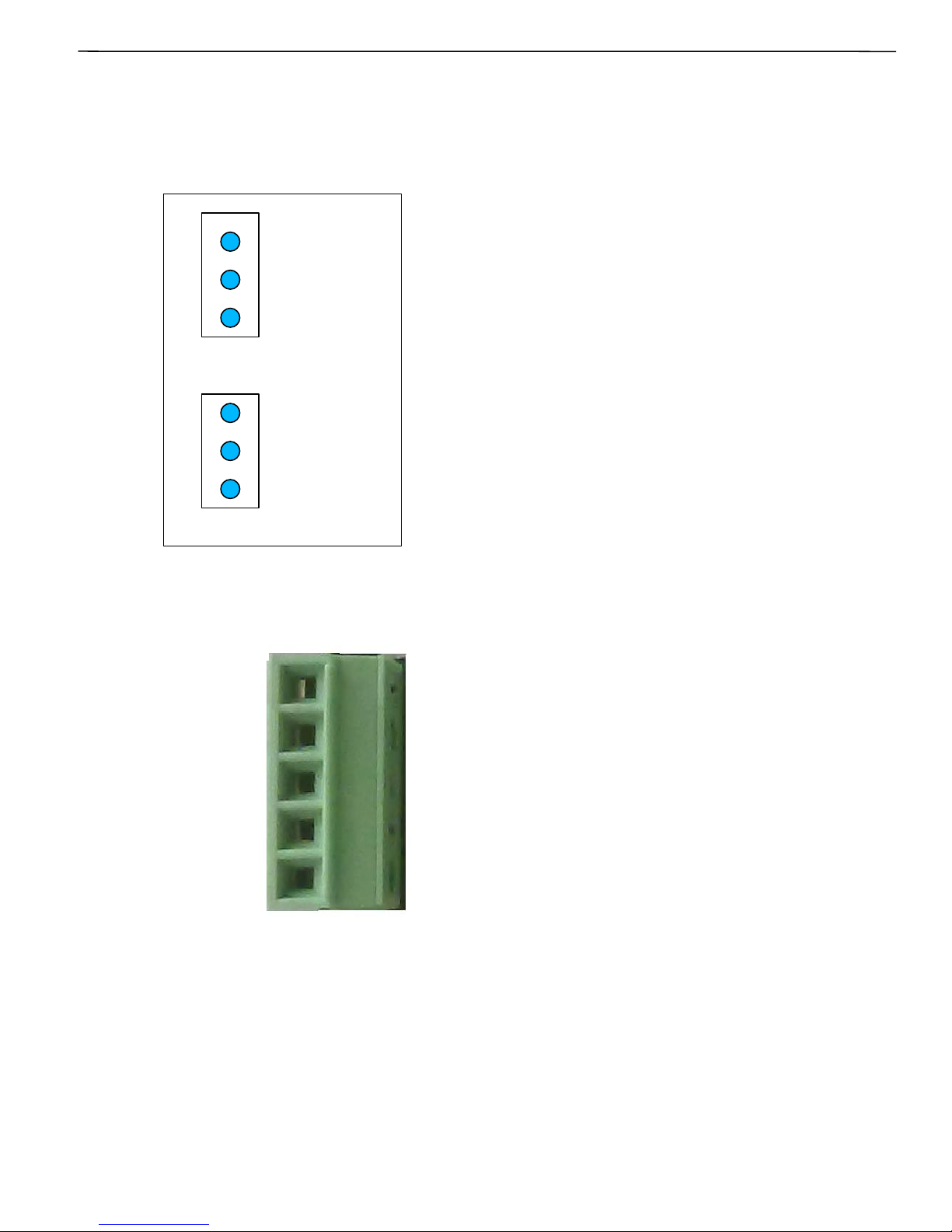
9. Jumper Selection for RS485 and GSM communication
(Continued):
14 of 56 Version 1.1.5 22nd March, 2016
Fig: Berg Jumpers selection for RS232 or RS485 Interface.
Fig: Connector for RS232 and RS485
Selecting positions 1 & 2 in both JP1 and JP2
enables RS232 communication for external GSM
Modem.
Selecting positions 2 & 3 in both JP1 and JP2
enables RS485 for MOD-Bus ASCII or MOD-Bus
RTU protocol.
Contact us for RS232 to RS 485 converter
module for RS 485 communication between TPF56 and PC / PLC’s RS-232 Port, with Auto-DataDirection Control.
Figure shows connector for RS232 and RS485
Communication. RX and TX for RS 232
communication and D- and D+ for RS485
communication. Note that the Signal Ground
Terminal is common for RS-232 or RS-485.
Contact us for Separate Documents for MOD-Bus
and GSM Functionality Implementations.
Note:
Please remove the 5-way mating connector of
RS-232/RS-485 while installing the Unit in the
DIN Standard Cut-out on the Panel Door, and
replace it after the installation is done.
3
2
1
3
2
1
DI (RS485)
TX 1
TXD1 (RS232)
RO (RS485)
RX 1
RXD1 (RS232)
JP1
JP2
D+ (RS485)
D- (RS485)
GND
TXD-GSM(RS232)
RXD-GSM(RS232)
Page 15
V, I, PF and Power
Measurement
Block
Three channel
Supply (load)
current feedback
Front-Panel RS-232 for
Data Downloading
Calculation
Block for
• Energy Parameters
• Harmonic analysis
• Capacitor kVAr
Power
Supply
Keyboard,
Display &
other support
function
block.
Power Factor
Correction Block
+ event monitoring.
Outputs Commands
For Capacitor
Switching.
Transistorised o/p
Capacitor
switching
commands
Serial
Communication.
Channels - 2 Ports.
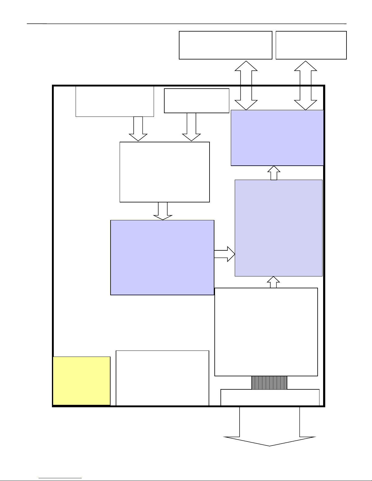
Functional Description:
Functional Block Diagram
Intelligent Power Factor Controller TPF-56
RTCC & Non-
Volatile Memory
for:
• Interval Log
• Event Log
• Prog. Param
• Critical data
with EWPF
logic.
15 of 56 Version 1.1.5 22nd March, 2016
3Ph 4Wire
Voltage feedback
Rear-Panel
RS232/RS485
Page 16
Functional Description (Continued):
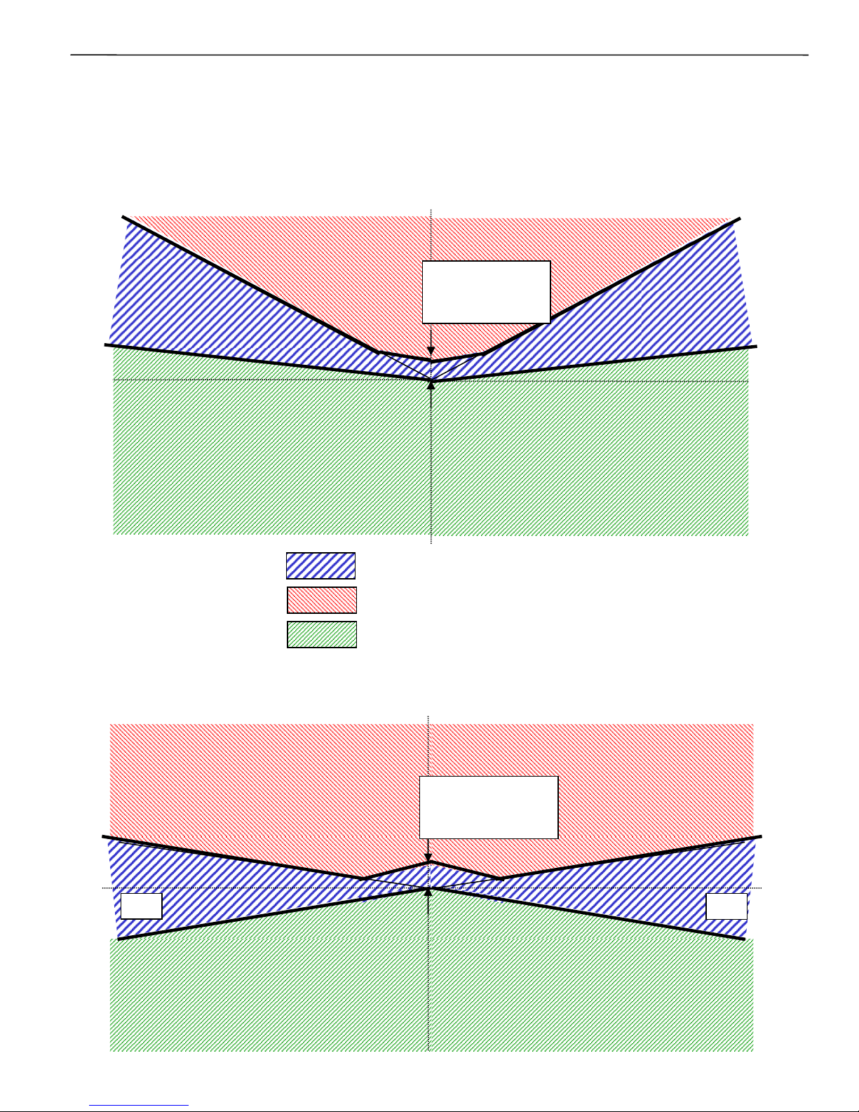
PF correction technique
KW.
KVAR
(Ind)
KVAR
(Cap)
PFLOWER.
PFUPPER.
- KW.
PFLOWER.
PFUPPER.
Case-1: PF-UPPER & PF-LOWER both set as inductive:
smallest
Capacitor bank
kVAr x 1.5 width.
KVAR
(Ind)
KVAR
(Cap)
PFLOWER.
PFUPPER.
- KW
PFLOWER.
PFUPPER.
smallest
Capacitor bank
KVAR X 1.5 width.
Case-2: PF-UPPER as Capacitive & PF-LOWER set as Inductive:
KW
No change band.
Capacitor addition band.
Capacitor removal band.
Intelligent Power Factor Controller TPF-56
16 of 56 Version 1.1.5 22nd March, 2016
Page 17
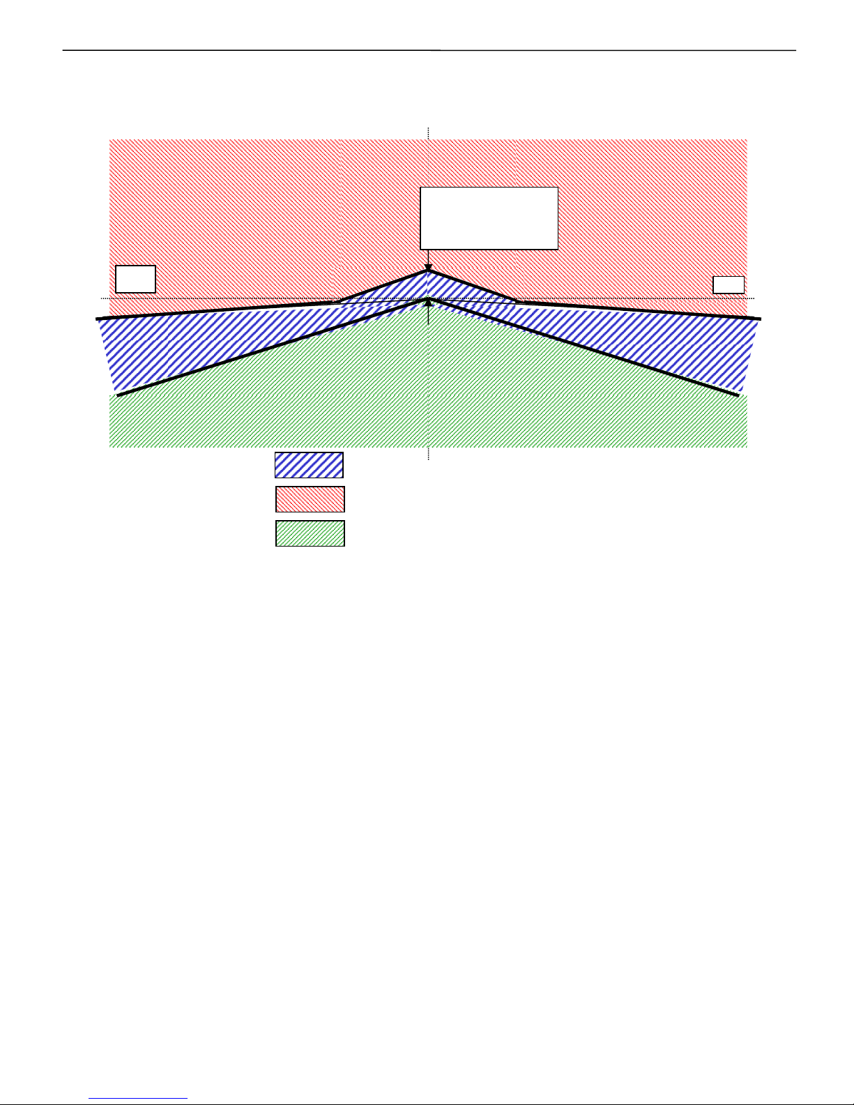
There are two PF set-points to be set in TPF-56/16. The UPPER limit and
the LOWER limit. TPF-56 ensures that PF-UPPER is never exceeded.
Additionally, “No change band” to minimum KVAR band size equal to
smallest bank KVAR x 1.5 ensures no hunting during the low KW loading.
TPF-56 is normally set for PF settings as per first two diagrams shown
where PFLOWER is inductive. This philosophy helps to optimize the
system maximum KVAR to be used as well as reduces the number of
switching operations during higher loading conditions. This ensures better
life expectancies of the switched capacitors as well as the switching
devices.
This methodology of KVAR compensation reduces the complex settings
that are used by conventional PF relays. The settings like C/K ratio and
KVAR offsets/shifts are eliminated which makes TPF-56 user friendly and
thus easy to commission.
For all the three conditions shown in the above diagrams, 4-quadrant
operation is achieved. Typical example of 4-quadrant operation is “CoGeneration Plants” and “Wind-Power Generation”. But with most
conventional consumer applications, only +Ve KW is seen, where the
Auto Synchronization feature can be used.
KVAR
(Ind)
KVAR
(Cap)
PFLOWER.
PFUPPER.
- KW
PFLOWER.
PFUPPER.
smallest
Capacitor bank
KVAR X 1.5 width.
KW.
Case-3: PF-UPPER & PF-LOWER both set as Capacitive:
No change band.
Capacitor addition band.
Capacitor removal band.
Intelligent Power Factor Controller TPF-56
17 of 56 Version 1.1.5 22nd March, 2016
Page 18
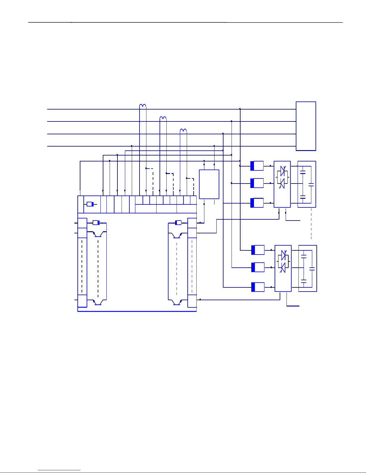
Typical wiring diagram for PF correction
Intelligent Power Factor Controller TPF-56
18 of 56 Version 1.1.5 22nd March, 2016
PH1
PH2
PH3
N
L
O
A
D
TPF-56
Capacitor Bank 1
Capacitor Bank n
S1S2
P1P2
S1S2
P1P2
S1S2
P1P2
Fuse
Fuse
Fuse
Fuse
Fuse
Fuse
External
+12 / +24 V
DC Supply
+ 0V
1Amp
EXT
Ground
CMD
+
_
CMD
+
_
External DC Supply
EXT Ground
External DC Supply
EXT Ground
Thyristor SW n
Thyristor SW n
PH1 PH2 PH3 N C 1A 1A 1AC C5A 5A 5A
PH2 PH3PH1
T1
T8
EXT
T9
T16
EXT
L1 L2
Fuse
Fuse Fuse
Page 19
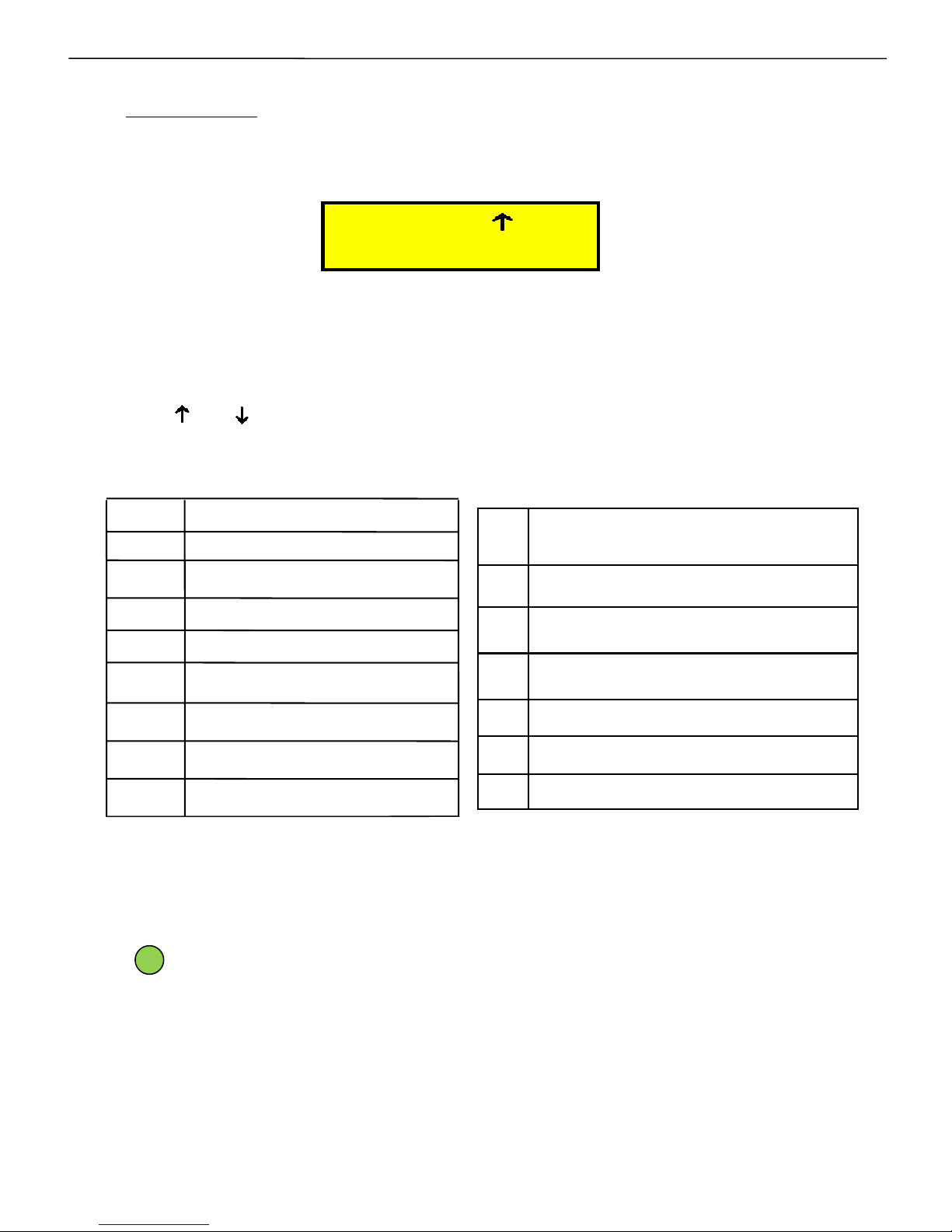
Front fascia –
LCD screen
First line of display indicates the PF value, inductive / capacitive PF,
mode of operation and fault /OK status:
“PF = 1.000” indicates the overall PF of the system.
“+” or “-” indicates if this PF is inductive or capacitive respectively.
“A” or “M” indicates the Auto and Manual mode of operation respectively.
“ ” or “ ” indicates the Mains and Generator mode of operation respectively.
“OK” (blinking) indicates status of the system, healthy or faulty.
Last two characters represent one of the following status:
Second line indicates the status of each capacitor bank by symbols.
‘I AM OK’ Blinking LED indicates the controller’s health status ,i.e. the
controller is working okay. If this LED stays continuously ON or
continuously OFF, then, it means the Controller is not functioning properly.
OK Controller status is OK
ZV Zero voltage
OV
Over voltage
UV
Under voltage
VH Voltage over-harmonics THD%
IH
Current over-harmonics THD%
BF Battery Fail for Battery or RTC faulty
ZC Zero current in any one phase
Intelligent Power Factor Controller TPF-56
AS Auto-Synchronization Pending
19 of 56 Version 1.1.5 22nd March, 2016
- I am OK (Blinking Green colour LED) to indicate the
healthy state of Controller.
OB
Out of Banks (Insufficient Total
Capacitive kVAr – Warning.
OT Over Temperature
UF Under Frequency
OF Over Frequency
UL Under Load
BL Low Battery Warning
OC System Over Current Warning
PF=+1.000 A OK
_ _ _ _ _ _ _ _ _ _ _ _ _ _
Page 20
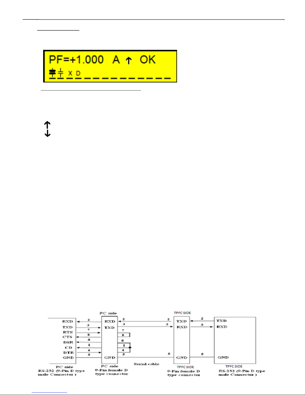
Example of a typical LCD display screen is show below:
Meaning of this screen contents:
Total no. of banks connected is 16.
Power Factor at Load sensing CT is ‘+1.000’
‘+’ indicates Inductive.(‘-’ indicates Capacitive)
Unit is operating in ‘A’ Auto mode. (‘M’ defines Manual mode)
“ ” indicates controller is on mains.
“ ” indicates controller is on Generator.
Total number of banks that are operational are 16.
Bank no. 1 is declared as fixed and is in ON condition.
Bank no. 2 is in ON condition.
Bank no. 3 is declared as faulty.
Bank no. 4 is in discharging state.
Bank no. 5 to 16 are in OFF condition.
“I AM OK”, flashing Green LED indicates the controller health status.
This LED is located at the extreme, left-hand, bottom side of the front
panel, as viewed by the user.
This LED, if continuously ON or continuously OFF, indicates
malfunctioning of the controller.
On powering up the unit, there is power-on discharge time given
for the capacitors to discharge completely. However, if the user is sure
that the capacitors are discharged, then on pressing the left key would
allow the controller to come out of the discharge time and thus user
need not wait for the discharge time to get complete and thus saves
time.
Front fascia –
LCD screen
This port is used for downloading of data logged in the controller.
The interface is Standard, 3-wire, RS232. For further description about
the data logging, please refer Page No. 36 of this user manual.
Following gives the pin configuration:
Front side RS232 communication port connection
Intelligent Power Factor Controller TPF-56
20 of 56 Version 1.1.5 22nd March, 2016
Page 21
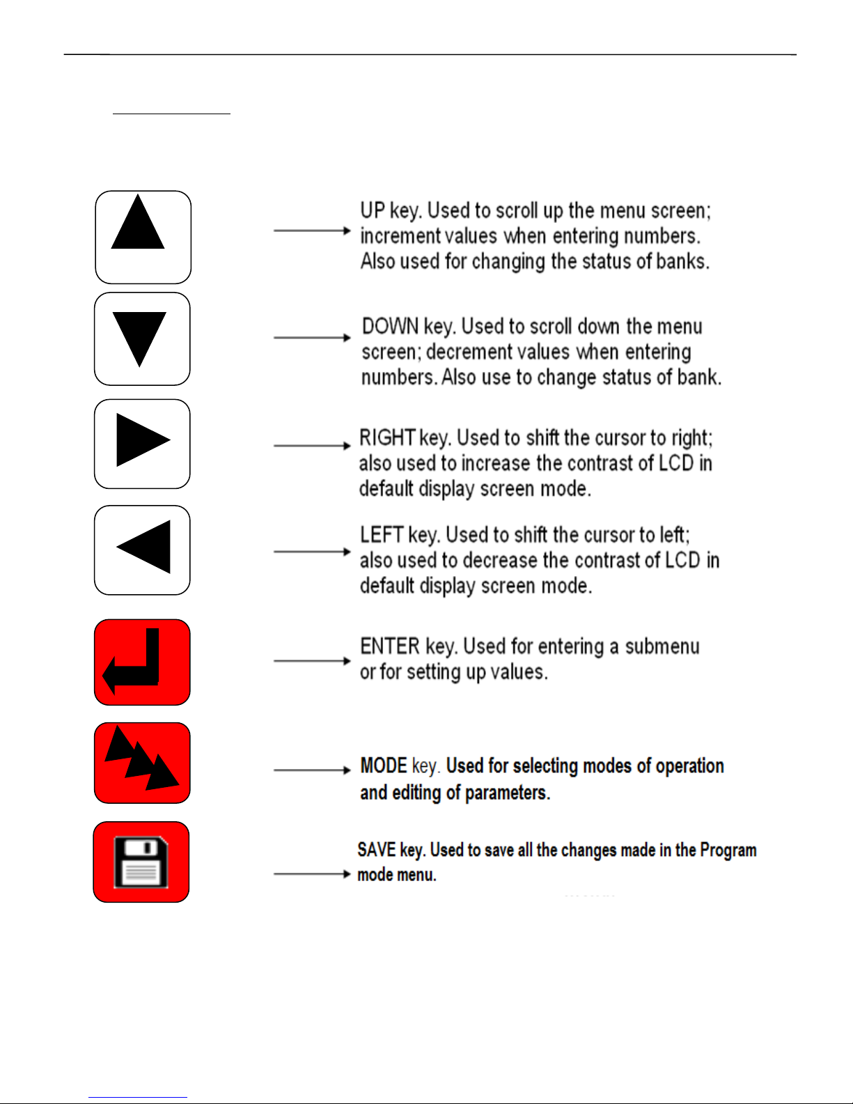
Front fascia –
Keypad
Intelligent Power Factor Controller TPF-56
21 of 56 Version 1.1.5 22nd March, 2016
Page 22

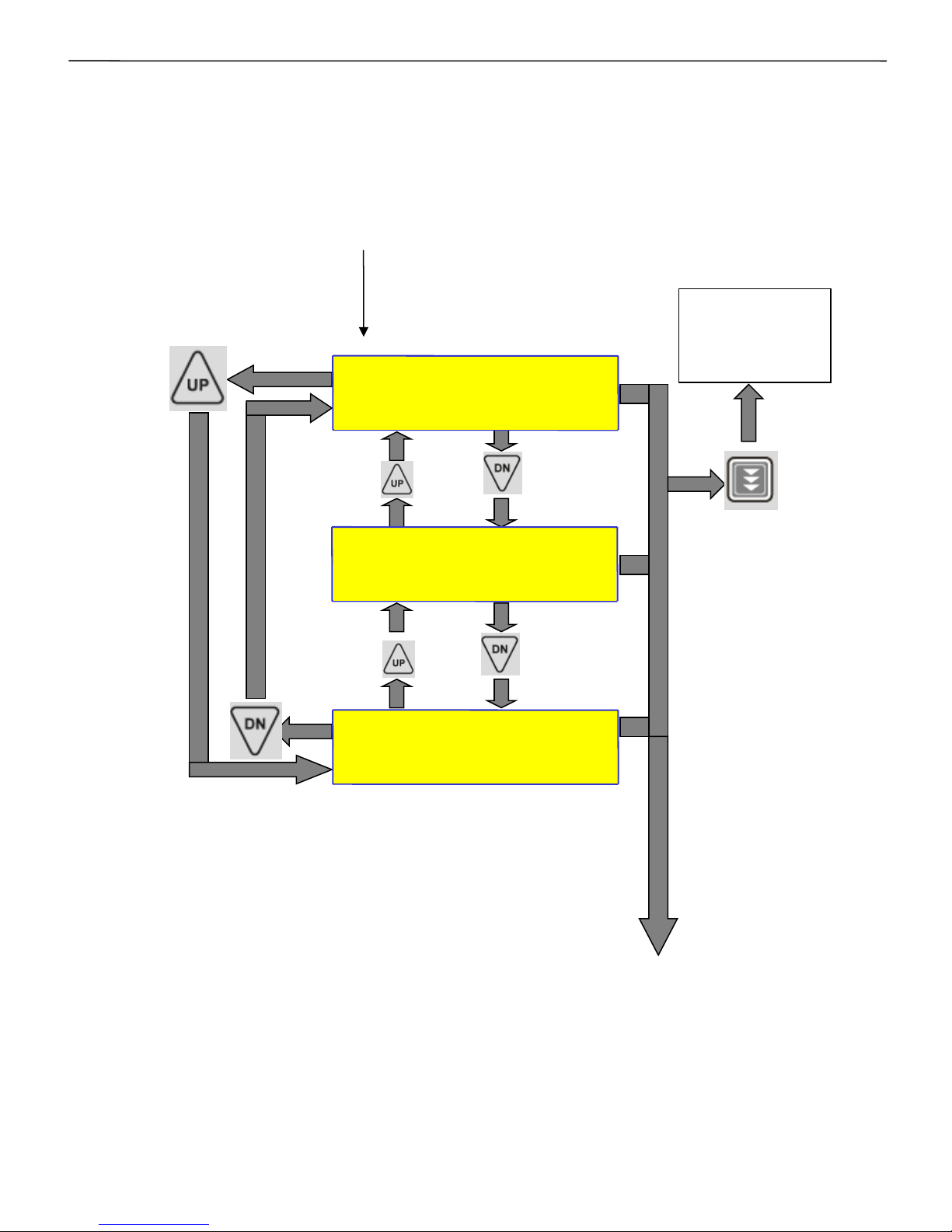
LCD Display Contrast & Back-light.
The LCD display Contrast is adjustable by front keyboard.
Repetitive strikes of “Right” key would increase the contrast
Repetitive strikes of “Left” key would reduce the contrast of
LCD display.
LCD – Background visibility light (Back-light) is turned on during Power
Up of TPF-56.
Any key on the Keypad pressed once, will turn on the Back-light of LCD
display.
Any non-activity on the keyboard for more than 1 Minute would turn off
the back-light of LCD display.
Intelligent Power Factor Controller TPF-56
22 of 56 Version 1.1.5 22nd March, 2016
Page 23
PF=+0.980 A OK
----------------------
DISPLAY
OVERALL VALUES
DISPLAY
PER-PHASE RMS
DISPLAY
POWER
DISPLAY
ENERGY
DISPLAY
HARMONICS
BATTERY VOLTAGE
3.15 VOLT
INT-Temperature
29 Deg C
TIME: 15:10:14
DATE:25/02/14
UNIT SR.NO
4600054100001
DISPLAY
MAXIMUM VALUES
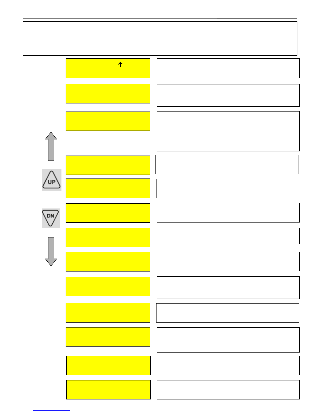
This is factory set default display screen giving
information on PF, mode, bank & controller status.
Overall values gives the average values of system
parameters – V, I, kW, kVAr, kVA, C-kVAr, frequency.
Max values gives the maximum values of V, I, kW,
kVAr and kVA, detected after the last reset. This also has
the facility of resetting the maximum values manually
which would be the actual instantaneous values and not
zero.
Per phase RMS gives the per phase values of voltage,
current, and neutral current.
Displays overall energy parameters like kWH, Inductive
& Capacitive kVArH, kVAH.
Displays THD in terms of “%” for per phase voltage and
current up to 15th odd harmonics.
Displays the Battery voltage of the Lithium Coin Battery
inserted in the Battery Holder.
Displays overall power parameters for per
phase like PF, kW, kVAr, kVA.
Display Sr. No of Controller. It is used for Data
downloading.
Display of various parameters
Values of various parameters can be viewed by using UP / DN keys & then pressing ENT
key. To exit a sub-menu press PROGRAM.
Intelligent Power Factor Controller TPF-56
Displays the internal (cabinet) temperature
of the TPF-56 Unit.
Displays current time & date that is from the internal
Real Time Clock-Calendar. Time is in HH/MM/SS (24
Hr) & date is in DD/MM/YY format.
23 of 56 Version 1.1.5 22nd March, 2016
TAS POWERTEK
VER. 1.0.5
Displays Name and the version of software.
DISPLAY
STEP KVAr
Displays the Step kVAr of the number of banks
connected.
Page 24

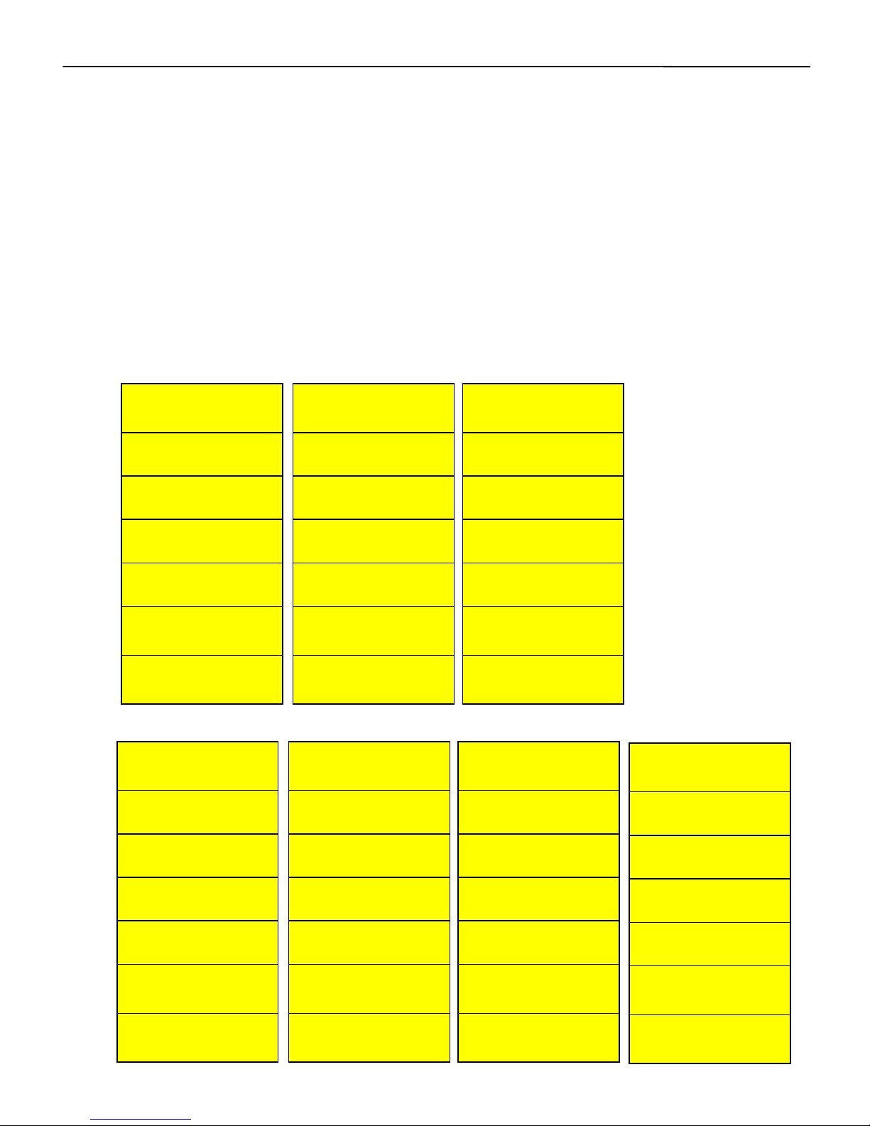
Sub-menu for display of parameters
Intelligent Power Factor Controller TPF-56
24 of 56 Version 1.1.5 22nd March, 2016
Overall
Values
Max.
Values
Per
Phase
RMS
Display
Power
Display
Energy
Display
Harmonics
Average
Voltage
00000.0 (L-N)
Maximum
Voltage
0000.0 V
R-Phase
Voltage
00000.0 (L-N)
R-Phase PF
1.000 IND
KWH
000000000.0
Vr-THD -F
000.0 %
Average Current
0000.0 A
Maximum
Current
0000.0 A
Y-Phase
Voltage
00000.0 (L-N)
Y-Phase PF
1.000 IND
IND
KVARH
000000000.0
Vy-THD-F
000.0 %
Active Power
00000.0 KW
Maximum KW
00000.0 KW
B-Phase
Voltage
00000.0 (L-N)
B-Phase PF
1.000 IND
CAP
KVARH
000000000.0
Vb-THD -F
000.0 %
Reactive Power
00000.0 KVAr
Maximum
KVAR
00000.0 KVAR
R-Phase
Current
0000.0 A
R-Phase KW
000000.0
KVAH
000000000.0
Ir-THD -F
000.0 %
Apparent Power
00000.0 KVA
Maximum KVA
00000.0 KVA
Y-Phase
Current
0000.0A
Y-Phase KW
000000.0
Iy-THD -F
000.0 %
C-KVAR
000000.0
RESET
MAXIMUM
VALUES
NO/YES
B-Phase
Current
0000.0A
B-Phase KW
00000.0
Ib-THD -F
000.0 %
Frequency
00.0 Hz
Neutral
Current
0000.0A
R-Phase KVAR
00000.0
In-THD -R
000.0 %
Y-Phase KVAR
00000.0
B-Phase KVAR
00000.0
R-Phase KVA
00000.0
Y-Phase KVA
000000.0
B-Phase KVA
000000.0 KVA
Page 25
continued..
Harmonic data of various current & voltage parameters can be
viewed by pressing ENT on the respective parameter screen of the
Harmonics menu. Following are the sub-menus giving the harmonic
data of voltage, current & capacitor current for each phase.
continued..
25 of 56 Version 1.1.5 22nd March, 2016
Intelligent Power Factor Controller TPF-56
Vr Harmonics
3rd:00.0%
Vr Harmonics
5th:00.0%
Vr Harmonics
7th:00.0%
Vr Harmonics
9th:00.0%
Vr Harmonics
11th:00.0%
Vr Harmonics
13th:00.0%
Vr Harmonics
15th:00.0%
Vy Harmonics
3rd:00.0%
Vy Harmonics
5th:00.0%
Vy Harmonics
7th:00.0%
Vy Harmonics
9th:00.0%
Vy Harmonics
11th:00.0%
Vy Harmonics
13th:00.0%
Vy Harmonics
15th:00.0%
Vb Harmonics
3rd:00.0%
Vb Harmonics
5th:00.0%
Vb Harmonics
7th:00.0%
Vb Harmonics
9th:00.0%
Vb Harmonics
11th:00.0%
Vb Harmonics
13th:00.0%
Vb Harmonics
15th:00.0%
Ir Harmonics
3rd:00.0%
Ir Harmonics
5th:00.0%
Ir Harmonics
7th:00.0%
Ir Harmonics
9th:00.0%
Ir Harmonics
11th:00.0%
Ir Harmonics
13th:00.0%
Ir Harmonics
15th:00.0%
Iy Harmonics
3rd:00.0%
Iy Harmonics
5th:00.0%
Iy Harmonics
7th:00.0%
Iy Harmonics
9th:00.0%
Iy Harmonics
11th:00.0%
Iy Harmonics
13th:00.0%
Iy Harmonics
15th:00.0%
Ib Harmonics
3rd:00.0%
Ib Harmonics
5th:00.0%
Ib Harmonics
7th:00.0%
Ib Harmonics
9th:00.0%
Ib Harmonics
11th:00.0%
Ib Harmonics
13th:00.0%
Ib Harmonics
15th:00.0%
In Harmonics
3rd:00.0%
In Harmonics
5th:00.0%
In Harmonics
7th:00.0%
In Harmonics
9th:00.0%
In Harmonics
11th:00.0%
In Harmonics
13th:00.0%
In Harmonics
15th:00.0%
V Harmonics
I Harmonics
Page 26
Method for keyboard / display usage
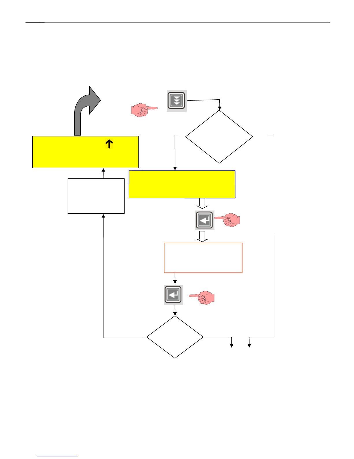
Flowchart for entering into different modes:
Enter the 4 digit
Password by using
& keys.
PRESS
Enable
If Password
Option is
Enable/Disable.
Disable
IF
PASSWORD
Correct?
NO YES
Continued on next page
*
PRESS
Enter Password:
****
Default
Display
mode
PRESS
Intelligent Power Factor Controller TPF-56
26 of 56 Version 1.1.5 22nd March, 2016
PF=+0.980 A OK
_ _ _ _ _ _ _ _ _ _ _ _
Page 27
*
#
1 2 3 4 5 6 7 8 9 10 11 12 13 14 15 16
Continued on next page
Select
1. Edit Parameter
Select
2. Auto Operation
Select
3. Manual Operation
Default
Display
mode
Intelligent Power Factor Controller TPF-56
27 of 56 Version 1.1.5 22nd March, 2016
Page 28
Operation in Auto Operation in Manual
Mode. Mode.
#
Select
1. Edit Parameter
Select
2. Auto Operation
Select
3. Manual Operation
PF= +0.980 A OK
_ _ _ _ _ _ _ _ _ _
Edit Parameters
General and IO
Edit Parameters
System
Edit Parameters
Fault
Edit Parameters
Step
Communication
Edit Parameters
General parameters
TPF-56 system related
parameters
Fault trip settings
Capacitor bank step settings
Communication related
parameters
Banks utilization counter
Intelligent Power Factor Controller TPF-56
28 of 56 Version 1.1.5 22nd March, 2016
PF= +0.980 M OK
_ _ _ _ _ _ _ _ _ _
Page 29

Mode Selection
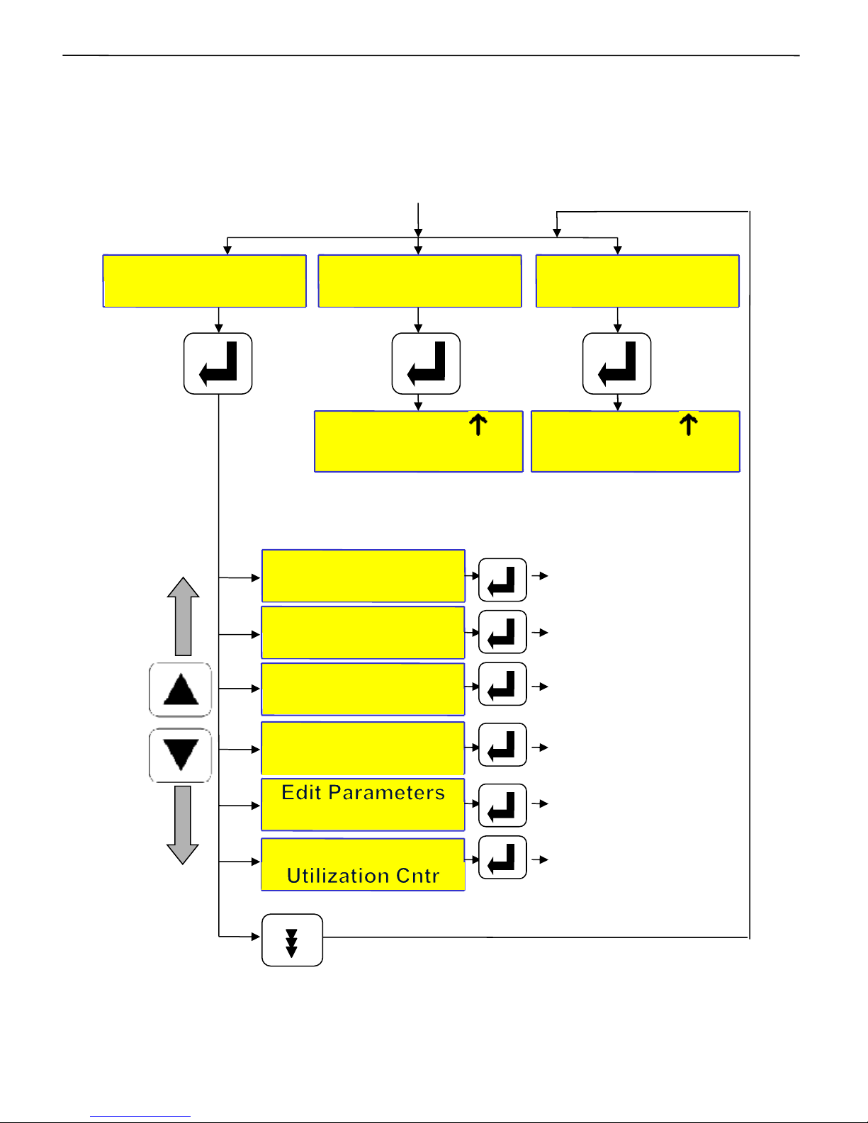
There are two modes of operation (Manual and Auto) and one mode for
data entry (Edit Parameters).
Press the PROGRAM key. Enter password (if enabled) by using
keys. Press ENTER Now using keys, select the Mode of operation:
• AUTO OPERATION
• MANUAL OPERATION
• EDIT PARAMETERS
Then press ENTER to enter the specific mode.
Auto Operation:
For functioning in automatic PF correction mode.
Manual Operation:
Pressing ENTER button, while on this screen, will put TPF-56 in Manual
mode. If user has switched to Manual Mode and for 5 minutes no key on
the keypad is pressed, then TPF-56 will automatically switch to Auto
Mode.
In manual mode the user can manually turn ON/OFF the banks. But
this is not allowable for all the faults. In case of the following faults,
turning ON the banks in manual mode is NOT allowed:
1] Under Voltage (UV)
2] Over Voltage (OV)
3] Under Frequency (UF)
4] Over Frequency (OF)
Entry in to Manual Mode of operation first turns-off all the Capacitor
Banks.
This mode is normally used to perform the operations like:
• Resetting of faulty banks to healthy status.
• Checking the Capacitor banks by turning them ON/OFF.
• Declaring specific bank/banks faulty. Masking of the banks so that once
auto mode is selected, these faulty declared banks would not be used for
PF correction.
For Declaring banks faulty or Resetting faulty banks:
While in Manual Mode default screen, press ENTER key.
The cursor above bank 1 will start blinking. Use keys to select the
specific bank. Then use key to declare it faulty.
To reset the faulty bank, bring the blinking cursor to that bank and use
key again to declare that bank as healthy.
After any of these operations press ENTER key so that cursor stops
blinking. To save the status on permanent basis (so that even after
Power-down, the status is unchanged), press MEMORY key. After saving
the settings, the unit will jump back to default mode. By default, the
controller is set to operate in AUTO mode.
Keyboard / Display operations
continued..
Intelligent Power Factor Controller TPF-56
29 of 56 Version 1.1.5 22nd March, 2016
Page 30

For Testing banks with Manual ON / OFF commands:
Press ENTER key, the cursor will start blinking. Use keys to select
the specific bank/s that are healthy and use key to turn ON and use
key to turn OFF that capacitor banks.
To come out of Manual ON/OFF edit mode, press ENTER key so that
cursor stops blinking.
…continued.
Edit Parameters:
This mode is used to carry out system settings. In this mode, various
system settings can be carried out. To do the same, use the keys
and select the type of parameters to be edited. The types of parameters
that can be edited are:
General & I/O : For general settings.
System : For TPF-56 system related settings.
Fault : Fault settings.
Step : Capacitor bank step settings.
Communication : Communication parameters.
Utilization counter: Bank operations utilization counters.
After selecting the type, press ENTER to enter the sub-menu of that
specific type.
The details of these sub-menus for every type is given further.
You can edit all these sub-menu settings by using the ENTER, , , ,
and keys
To come out of the sub-menu press MODE key once.
To store the edited parameters permanently, press MEMORY when you
are either in the Edit Parameters or any sub-menu area.
To come out of Edit Parameters without saving the changes, press MODE
key again.
Intelligent Power Factor Controller TPF-56
30 of 56 Version 1.1.5 22nd March, 2016
Page 31
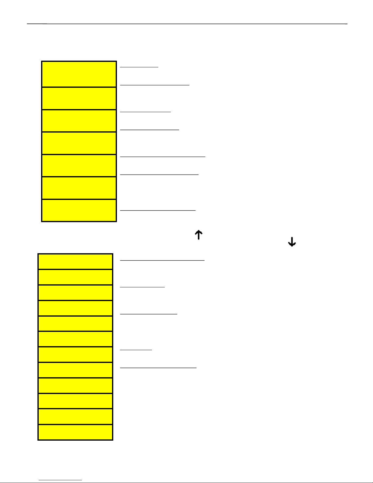
Rated Supply voltage :User can set rated supply voltage of
panel.
Ext-PT ratio: In case the external PT is used, this ratio can
be set.
Cur CT Primary: Rated Feedback Load current for mains.
NOTE: PT ratio and CT Ratio are adjusted such that Panel
VA Rating Should not Exceed 50 MVA.
DT Ratio: Set the distribution transformer ratio.
Power Factor Limits: PF limits can be set as inductive or
capacitive. Also Target PF band can be set as Upper PF and
Lower PF limit. These limits can be set for Mains & or for
Generator.
Password: Enable or disable password.
Change Password: Set new value of password (4 digit).
Factory default password is “0000”.
Load Default: Loads factory set default parameters.
THD to Display: Type of THD to be displayed for V and I. RTHD (RMS), F-THD (fundamental).
Reset Energy Counter: Reset all energy counters to zero.
AUX OP1 FUNCTION :Program the auxiliary output to
become NC due to any of the following :None, TripFlt,
Sys Flt, OutOfBank.
AUX IP1 FUNCTION : Set an action through auxiliary input
None ,O/P En Di (output enable disable) , Mains/generator,
Reset Bank Flt. When controller is on Mains mode then on
main screen shows (arrow). And if controller is on
generator mode then on main screen shows (arrow).
General & I/O
continued..
System
Intelligent Power Factor Controller TPF-56
31 of 56 Version 1.1.5 22nd March, 2016
CUR CT Primary
: 1000
PF Up Lim: Mains
[Cap : 0 ] 0.999
PF Up Lim: Mains
Cap: 0 [0.999]
PF Low Lim: Mains
[Ind : 1] 0.990
PF Low Lim: Mains
Ind : 1 [0.999]
Password
Disable :
Change Password
: 0000
Load Default
No :
THD To Display
F-THD :
Reset energy Cnt
No :
AUX OP1 FUNCTION
None :
AUX IP1 FUNCTION
None :
EXT-PT Ratio
0001.0 : 1
Rated Supply Vtg
(L-N) : 0254.0 V
DT Ratio
0001.0 : 1
PF Up Lim: Gen
[Cap : 0 ] 0.820
PF Up Lim: Gen
Cap: 0 [0.820]
PF Low Lim: Gen
[Cap : 0] 0.800
PF Low Lim: Gen
Cap : 0 [0.800]
Page 32
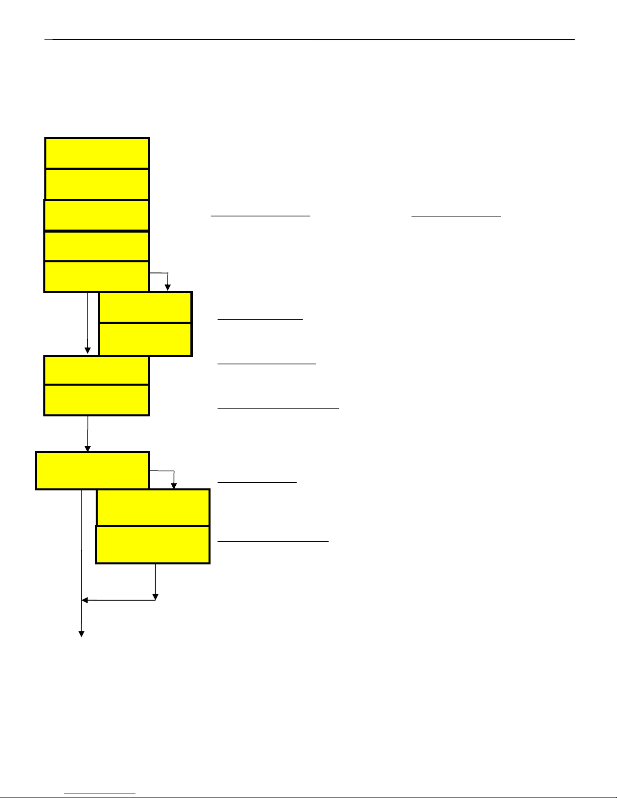
For over-voltage and under-voltage fault, the option
available is as hereunder:
1=Fast Off Step
For all the faults, normally two limits are defined. One is
Detection Limit and another Resume Limit. Detection
Limit if exceeded (above/below) by the parameter would
mean the action as defined by parameter in type of fault
(as given here-above). Resume Limit defines the
parameter value above/below which the fault is
deactivated.
• Over-Voltage: As name suggests, its for Over-Voltage
conditions persisting in any one phase for 3 sec.
• Under-Voltage: For Under-Voltage conditions in any one
phase persisting for 3 sec.
• Under Load fault: The values here are set as % of
Maximum rated kW. This is useful in case of banks are put
in circuit to take care of no load compensation. Value for
this Under-Load KW can be calculated as shown here.
•Over current: The TPF-56 detects if the supply system is
overloaded, then it is for warning indication. No capacitor
banks are switched off with this detection.
•Temperature fault: As the name suggests, it displays the
over temperature fault if the temperature exceeds the set
limits. There are two parameters related to it, i.e. the
temperature upper limit and lower limit. If fault is set,
then “Fast Off step” action is undertaken.
Fault
continued..
Over voltage
Limit (%) : 113
Over voltage
Resume (%) : 110
Under voltage
Limit (%) : 068
Under voltage
Resume (%) : 071
Under load
Limit (%) : 02
Under load
Resume (%) : 03
Under load KW Flt
Off Step :
IF ENABLED
IF
DISABLE
#
Over Current
Limit (%) : 100
Over Current
Resume (%) :095
Intelligent Power Factor Controller TPF-56
Temperature Flt
Fast off :
Temperature
U. limit : 70
Temperature
L. limit : 60
IF Fast off
IF
DISABLE
32 of 56 Version 1.1.5 22nd March, 2016
Page 33
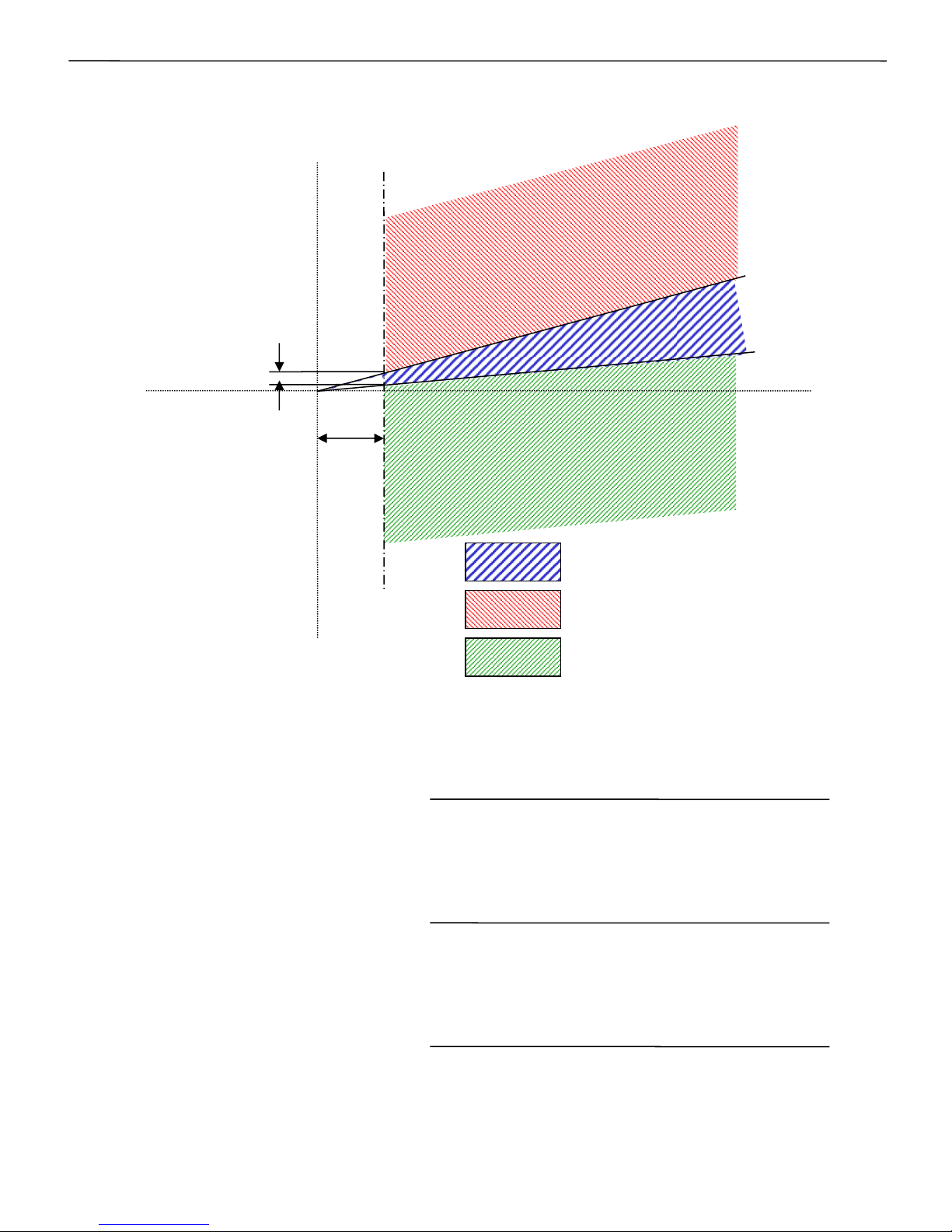
Under-Load kW value setting =
1.5 x Smallest bank kVAr.
[tan{cos -1(PFUPPER)} + tan{cos-1(PFLOWER)}]
For PFUPPER Capacitive and PFLOWER Inductive :
For PFUPPER Inductive and PFLOWER Inductive :
Under-Load kW value setting =
1.5 x Smallest Bank kVAr.
[tan{cos -1(PFLOWER)} – tan{cos-1(PFUPPER)}]
Under-Load kW value setting =
1.5 x Smallest bank kVAr.
[tan{cos -1(PFUPPER)} – tan{cos-1(PFLOWER)}]
For PFUPPER Capacitive and PFLOWER Capacitive:
Under Load settings:
KW.
KVAR
(Ind)
KVAR
(Cap)
1.5 x smallest
Capacitor bank
PFLOWER.
PFUPPER.
KW
UnderLoad.
No change band.
Capacitor Addition band.
Capacitor Removal band.
Intelligent Power Factor Controller TPF-56
33 of 56 Version 1.1.5 22nd March, 2016
Page 34
Intelligent Power Factor Controller TPF-56
34 of 56 Version 1.1.5 22nd March, 2016
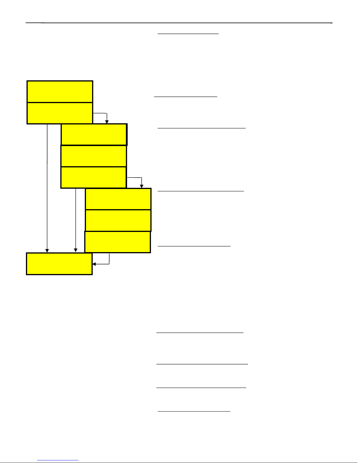
•Out of Banks Fault: This is only with Disable and
Enable options. If Enabled, then unit will indicate the
out of bank fault if for two consecutive correction
cycles, PF is more inductive than Lower PF set point
and all the healthy capacitor banks are in ON state.
In short, the total Capacitive KVAr is less that the
required, to maintain PF within the limits set.
Harmonic Overload: This has two options, namely
Disable and Fast Off.
This is basically to indicate the harmonic faults.
•V-THD Threshold limit (%):. If percentage of voltage
THD is above the set limit, then voltage harmonics
fault (VH) will be displayed on the default screen.
Average THD in any one phase over 3 min period if
exceeded, then this fault is activated.
The VTHD limit can be set through V-THD threshold
limit screen.
•I-THD Threshold limit (%):If percentage of current
THD is above the set limit, then current harmonics
fault (IH) will be displayed on the default screen.
Average THD in any one phase over 3 min period if
exceeded, then this fault is activated. The I-THD limit
can be set through I-THD threshold limit screen.
•Harmonic Flt Auto-Rst: This fault has two options,
namely Enable and Disable. If it is enabled and
Harmonics exceeds from the set limits then
controller switch OFF all the capacitor bank steps
until harmonics come down within set limits. After
harmonics comes below the set limits controller
clears the fault automatically after a period of 180
seconds & is ready to switch ON the capacitor bank
steps. and if disable controller shows the fault until
you reset the fault manually.
•Harmonic Lmt Ext Loading: User can set the actual
load limit in percentage of rated load here for which
harmonic fault can be detected.
•Low Rng Mul Fact For VTHD: By setting this factor
user can extend the VTHD fault limit.
•Low Rng Mul Fact For ITHD: By setting this factor
user can extend the ITHD fault limit.
•Bank Health tolerance: In the capacitor bank health
check monitoring, this indicates the tolerance
between the user set bank kVAr values and the
actual kVAr as calculated by the controller.
…continued.
Out of banks Flt
Disable : 0
Harmonic overload
Disable : 0
I-Thd threshold
Limit(%) : 18
V-Thd threshold
Limit(%) : 03
Harmonic Flt Auto Rst
Disable : 0
Out of banks Flt
Enable :
Harmonic overload
Fast Off :
I-Thd Threshold
Limit(%) : 025
V-Thd Threshold
Limit(%) : 05
Har Flt Auto-Rst
Enable :
Bank health tolerance
Tolerance : 20%
IF ENABLE
IF
ENABLE
IF
DISABLE
#
IF
DISABLE
Harmonic Lmt Ext
Loading(%) : 20
Low Rng Mul Fact
For VTHD:3.0
Low Rng Mul Fact
For ITHD:4.0
Page 35
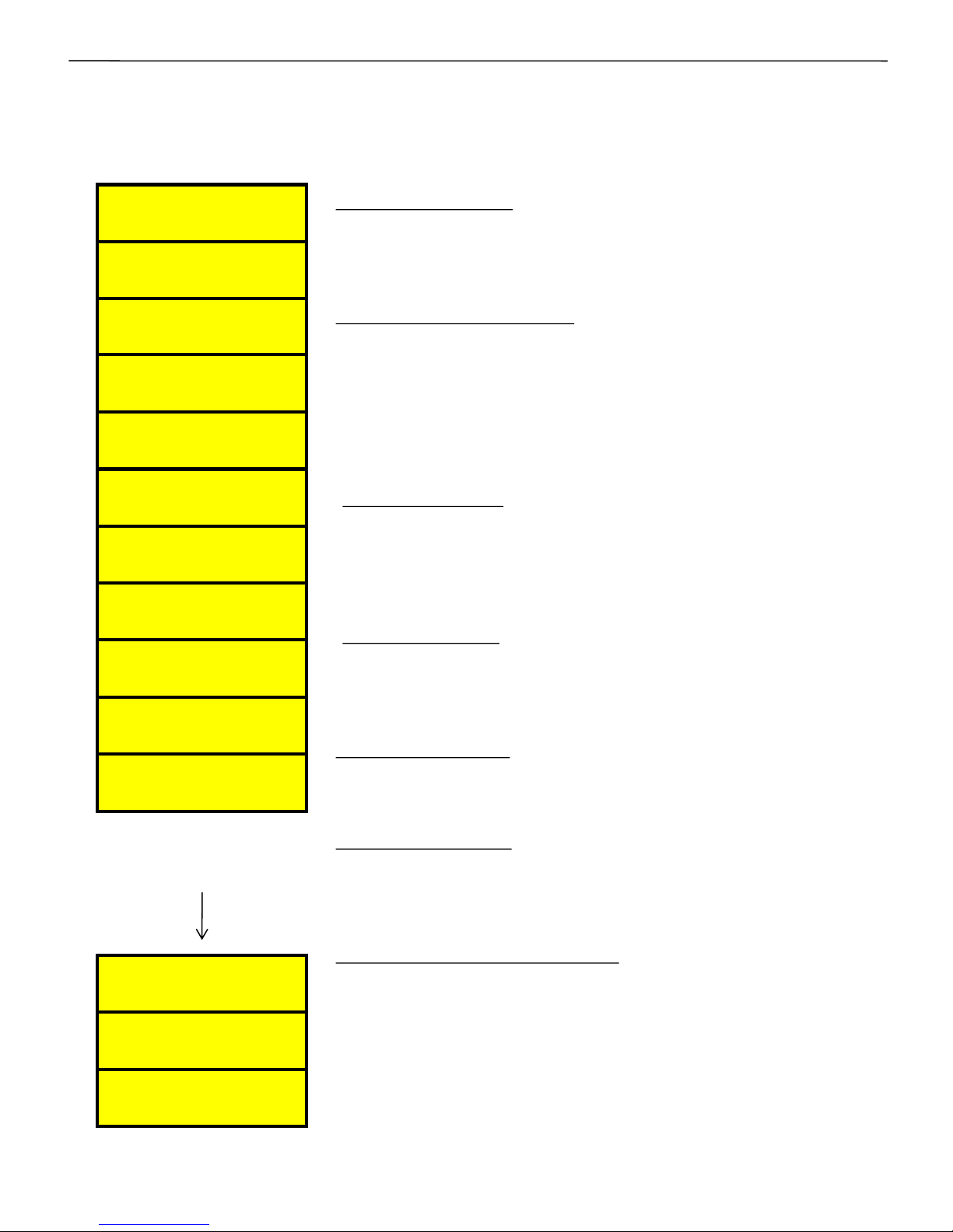
•Steps Connected: Defines the number of operational
steps . Depending on the capacitor bank steps of the
APFC system, this parameter is set. Maximum 16 banks
can be connected.
•Capacitor Bank Voltage: Capacitor bank voltage line-to-
line value is defined here. i.e. it defines the Voltage value
at the defined kVAr.
• Smallest kVAr safety Fact: This factor defines the no
action zone prohibiting the capacitor bank On/Off
operation to avoid hunting.
• Correction Time: Defined in cycles. This is the Time
between two consecutive kVAr compensations i.e time
between change in load kVAr demand & subsequent
switching of capacitor bank steps. This can be set within 1
to 240 line Cycles.
• Discharge Time: Time defined here is the time for
discharge of the capacitors to a level, so that they can be
turned ON again. This can be set within the range of 1 sec
to 300 sec.
•IntrLeaving Dely: This is the switching delay between
two bank execution. User can set it as instantaneous or 1
Sec as a option.
•Fixed bank setting: In this, any bank(no of banks
depends upon the steps connected) can be set as fixed
bank.
•Unequal Bank kVAr [1….16]: The capacitor bank step
configuration values are to be set here .These parameters
are to be defined for each bank kVAr (at defined
Capacitor Bank Voltage). TPF-56 has an in-built intelligent
algorithm to select the best possible combination to suit
the exact kVAr requirement for compensation.
Step
continued..
Intelligent Power Factor Controller TPF-56
35 of 56 Version 1.1.5 22nd March, 2016
Steps Connected
: 16
Smallest KVAr
Safety Fact: 1.5
Correction Time
Cycles: 00050
Discharge Time
Seconds: 00010
Fix – Bank Setting
_ _ _ _ _ _ _ _ _ _ _ _
Unequal Bank [1]
KVAR :012
Unequal Bank [2]
KVAR :012
Unequal Bank [3]
KVAR :012
Unequal Bank [4]
KVAR :018
Unequal Bank [15]
KVAR :150
Unequal Bank [16]
KVAR :180
Unequal Bank [14]
KVAR :125
.
.
.
Define KVAR Vtg
(L-L) : 00440 V
IntrLeaving Dely
1 SEC:
Page 36
.
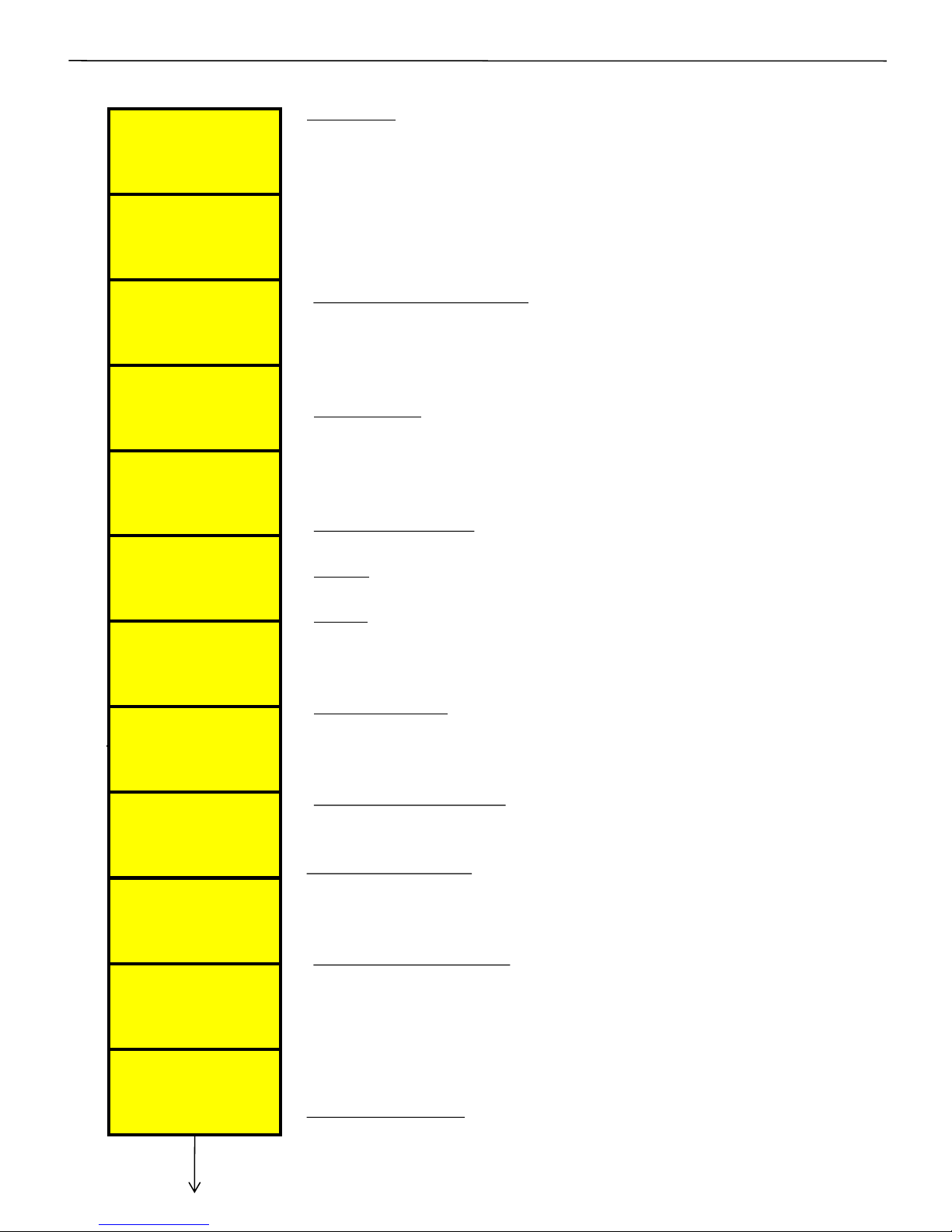
•Panel ID: Value - 00000001 to 99999999. Default value
00000001. Defines the 8 digit Panel ID, used for serial
communication on RS-232 Dedicated protocol, and for
further analysis of down-loaded data. The panel ID can be
changed and a new Panel ID can be saved only if all the
logged data is Erased from the EEPROM. This is to prevent
false data.
• Erase Data for New ID: Yes and No.
It erases all the logged data in the EEPROM. The panel ID
can be changed and a new Panel ID can be saved only if all
the logged data is Erased from the EEPROM.
• Baud Rate: selectable.
4800bps, 9600bps, 19200bps, 57600 bps. The Baud rate
should match on both sides, TPF-56 & PC/HHU for
communication.
• Real Time Clock: Defines the Real Time Clock / Calendar
setting.
• Time: Defines Hours (24 Hours Clock), Minutes and
Seconds ( HH:MM:SS ) format.
• Date: Defines the date, month & year setting.
(DD:MM:YY) format.
The above applicable only after saying “Yes” to initialize
RTC, by pressing Up key.
• Initialize RTC: Yes and No.
Defining “Yes” initializes RTC (real time clock) to the
specified set values.
• Clear Battery fault: Yes and No.
Defining “Yes” clears Battery fault and/or NV RAM fault in
TPF-56.
•Select LOG Time : 60 MIN , 30 MIN , 15 MIN ,
10 MIN . By pressing UP key it Define log data at 60
/30/15/10 MIN interval period.Default value is 60 min.
• EraseData4LOGTime : Yes and No.
Defining “ Yes ” erase all previously logged data from the
EEPROM . Select LOG Time can be changed and new
Select LOG Time can be saved only if all logged data is
erased from the EEPROM. This is to maintain time
synchronization of data.
•COM 2 Function : None, Mod-bus ASCII , Mod-bus RTU,
GSM. Option Mod-bus ASCII & Mod-bus RTU for RS485
communication and GSM for RS 232 communication for an
external GSM/GPRS MODEM.
Communication
Intelligent Power Factor Controller TPF-56
36 of 56 Version 1.1.5 22nd March, 2016
Select LOG Time
60 MIN :
EraseData4LOG Time
No :
COM 2 Function :
Modbus RTU :
#
OvrWrt INTER LOG
No :
OvrWrt EVENT LOG
Yes :
Panel ID
00000001
ErasData 4 NewID
No :
Set Date
DD:MM:YY
Baud Rate - COM1
57600 :
Set Time
HH:MM:SS
Clr Battery Flt
No :
Initialize RTC
No :
Page 37
Intelligent Power Factor Controller TPF-56
37 of 56 Version 1.1.5 22nd March, 2016
continued..
#
Baud Rate – COM 2
9600 :
Service Provider
0000000000
SMS Receiver No.
0000000000
• Baud Rate: selectable.
4800bps, 9600bps, 19200bps, 57600bps. The
Baud rate should match on both sides, TPF-56 &
GSM/GPRS for communication.
• GSM Service Provider: GSM service provider
number is to be given. It is a 10digit number. The
Country Code of 91 is internally pre-fixed by the
Controller.
• SMS Receiver No: This defines the number to
where the SMS communication is to be sent.
Normally it’s a Master control unit Receiver
Number. This is a 10 Digit Number.
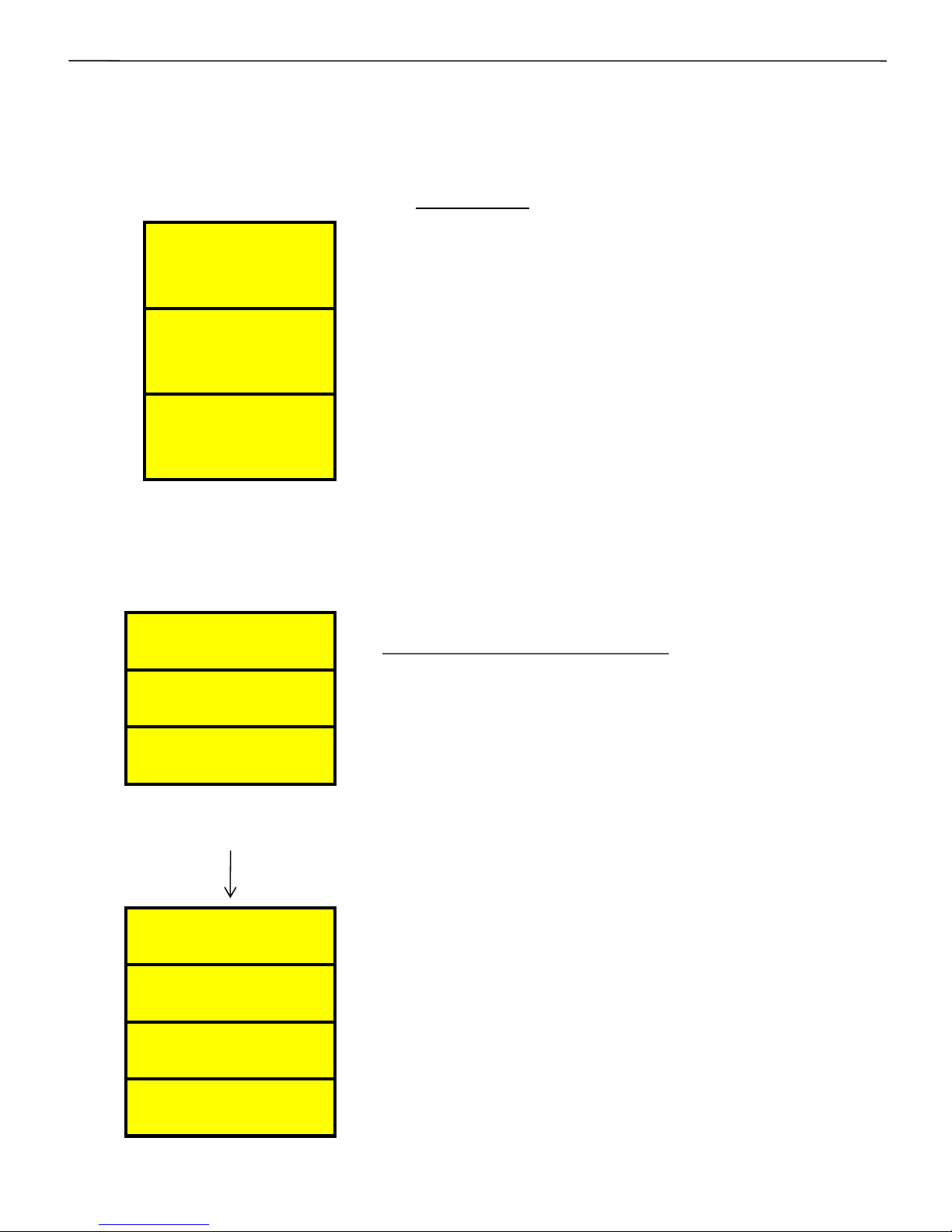
Utilization Cntr
B1 :0000000000
Utilization Cntr
B2 : 0000000000
Utilization Cntr
B3 : 0000000000
Utilization Cntr
B13 : 0000000000
Utilization Cntr
B14 : 0000000000
Utilization Cntr
B15 : 0000000000
Utilization Cntr
B16 : 0000000000
Utilization Counter, (NOT editable in the field):
Utilization counters: Bank nn: This gives the time
in seconds for which the bank is ON.
All Counters are initially set to “0000000000” at
the time of factory testing.
.
.
Page 38
Notes on Protection and Functionalities:
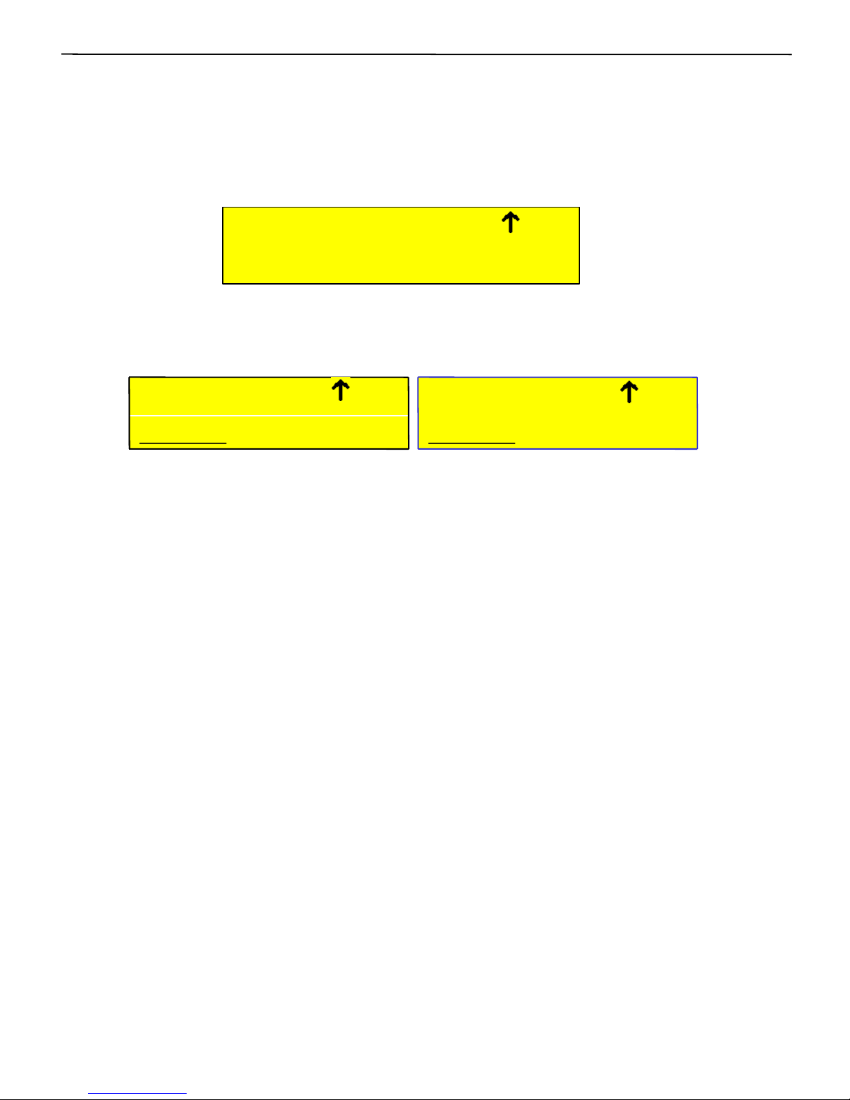
(1)If current CT connections are not connected to the TPF-56 unit i.e.
if no current is detected or the detected current is below 1.5% of
rated load current, then, TPF-56 would show the following display
on the LCD.
(2) If Harmonics overload fault is enabled, and if the voltage or current
THD exceeds the set limit, then TPF-56 would show the following
display on the LCD.
Pressing the Enter key, would reset the VH/IH fault even if
voltage/current THD is above the set limit. The fault indication would
continue till the respective THD is above the set limit. In case of THD
above limit, all capacitor banks are switched off to protect them.
TPF – 56 also have a parameter called Harmonic Fault Auto-
Reset. If enabled, then the controller automatically clears off the
harmonic fault after 180 seconds when the harmonic level falls
down below the Set limits
(3) Battery Low :If the internal Lithium coin Battery Voltage of nominal
3 V drops below 2.6 V then the controller will flash “Battery Low!!!”
message on the Default screen display (in a blinking state with certain
delay) until the battery is replaced by a new healthy battery. Please
note that even when the “Battery Low!!!” message is being flashed on
the LCD display the user can still operate the keypad.
It is essential to have the battery operational to maintain the Real
Time Clock and Calendar information. If the Battery Voltage falls
below certain limit, the RTCC will stop functioning. All Data Logging
operations are prohibited if the RTCC is Stopped.
Intelligent Power Factor Controller TPF-56
DDDDD ENT TO RST
PF= +0.980 A VH
DDDDD ENT TO RST
PF= +0.980 A IH
PF = + ?.??? A ZC
_ _ _ _ _ _ _ _ _ _ _ _
38 of 56 Version 1.1.5 22nd March, 2016
Page 39

(4)Battery Replacement: The RTCC Battery is Maxell Make, CR2032 type.
This can be replaced without opening the Controller through the Slot
provided on the Top Left-Hand side of the Controller.
The Old Battery should be removed using insulated tip plier and a new
Battery is to be placed using the same insulated tip plier.
Please observe the correct positive and negative polarity of the Battery
while replacing.
The positive of the Battery should be towards the viewer (LCD Side) and
the negative towards the PCB. It is always recommended to replace this
battery with Auxiliary supply to the Unit in ON condition. This would
prevent re-setting up of RTCC date. Still if one wishes, it can be safely
done with unit in Power down condition too without fear of loosing data.
Note: Unit is equipped with EWPF logic. With Battery Faulty condition or
Battery Low condition, Battery Replacement can be safely done without
data download and without a fear of loosing any logged data or Energy
Counter values or Capacitor bank logged kVAr values. Such battery
replacement can be even safely be done with unit in power down
condition.
Intelligent Power Factor Controller TPF-56
39 of 56 Version 1.1.5 22nd March, 2016
Page 40

Intelligent Power Factor Controller TPF-56
TPF-56 Controller fault indications and fault actions
Sr.No.
Status
Indications
on LCD
Display
Status / Fault Description
Programmable
Options
provided on
Fault Fault description
Action taken
by TPF-
56
controller
Status
appearing in
Data
Logging
Enable / Disable
/ Indicative /
Fast OFF
If Enabled Yes / No
1 OK Controller status is OK
Yes
2 ZV Zero Voltage
Not
programmable
If voltage absent in any
one of the three phases
Fast OFF Yes
3 OV Over voltage
Not
programmable
(Fixed enable)
If voltage exceeds than
defined limit in any one
of the 3 P-N values Fast OFF Yes
4 UV Under Voltage
Not
programmable
(Fixed enable)
If voltage reduces than
defined limit in any one
of the 3 P-N values Fast OFF Yes
5 VH
Voltage over-harmonics
THD%
Enable / Disable
If V-
THD exceeds than
defined limit , in any one
of the 3 P-N values Fast OFF Yes
6 IH
Current over-harmonics
THD%
Enable / Disable
If I-
THD exceeds than
defined limit, in any one
of the 3 P-N values Fast OFF Yes
7 BF Battery for RTC faulty
Not
programmable
Battery
checked as un
-
usable
Stops data
logging Yes
8 ZC Zero current
Not
programmable
Load Current less
than
1.5%
in any one of the
three phases Fast OFF Yes
9 OB Out of Banks
Enable / Disable
Insufficient bank kvar Indicative Yes
10 OT Over temperature
Fast off / Disable
Indicates
temperature inside
the APFC controller Fast OFF Yes
11 UF Under frequency
Not
programmable
If reduces below
47Hz
(limit) Fast OFF Yes
12 OF Over frequency
Not
programmable
If exceeds 53Hz (
limit)
Fast OFF Yes
13 UL Under Load
Enable / Disable
If KW reduces than
defined limit, in any one
of the 3 P-N values
Fault OFF
(only normal
banks off) Yes
14 OC Over current
Enable / Disable
Load Current exceeds
than defined limit, in any
one of the 3 P-N values
Indicative Yes
15
Battery Low!!!
Low battery
Not
programmable
Battery
Voltage drops
below 2.6 V Indicative Yes
16 NF Neutral Fault
Not
programmable
Shifting of neutral voltage
away from balanced
condition Fast OFF Yes
40 of 56 Version 1.1.5 22nd March, 2016
Page 41

Intelligent Power Factor Controller TPF-56
Events and interval based data-logging facilities:
The TPF-56 has non-volatile memory where internal operational status is
monitored and change of state, called as an “Event”, is internally recorded in
the non-volatile memory, with RTCC date & time stamping for the event data.
Up to 1024 latest events are held in the memory which can be off-loaded
from the controller to a PC or to a hand-held unit (HHU) for further analysis.
This information is useful to the user because the user comes to know when
a particular fault occurred and when the controller resumed from the faulty
condition.
The “Data View” Application Software for PC, is provided to the users of
TPF-56 Unit to download and process the data directly from the TPF-56 using
a laptop/PC or download from Hand Held Unit(HHU), if the HHU already has
the data from TPF-56. A separate User Manual is available for the “Data View”
Software.
“Data View” is for not only for data downloading from the TPF-56 Units, but
also for presenting the captured information in a User-Friendly manner.
TPF-56 Unit is capable of internally logging various important Electrical
Parameters as well as the Capacitor Bank Status, on a fixed Time Interval
Basis.
The most common Time Interval provided is that of 1 Hour, therefore the
data-logging is on an Hourly basis.
Thus, the Hourly logged records in the TPF-56 Unit are first downloaded by
“Data View”, and then, analysed and presented to the User in various ways.
“Data View” is capable of generating the reports in visual forms as well as in
print form for hard-copy storage.
The Non-Volatile Memory of the TPF-56 Unit is capable of logging the Hourly
Data for a maximum duration of 124 days. The “Data View” downloads all
logged data of 124 days. Selecting shorter time interval period for logging will
correspondingly reduce the number of days for the logged data because the
amount (size) of memory for data-logging, is internally fixed in the design.
“Data View” has the ability to show the date of downloading and expected
date of next download. Time span between date of downloading and next date
of downloading is 90 days.
This facility allows about One Month margin to get the data from the field.
This is important so that one actually does not miss any field data.
If the logged-data is not off-loaded from the Controller in time, the old data
will be over-written by the Controller to always present the latest data.
41 of 56 Version 1.1.5 22nd March, 2016
Page 42

For the maintenance purpose, it is possible to generate “faults” related
information for a particular date and time. It also possible to see the Status
of the Capacitor Banks of TPF-56 Unit, at a specified date and time.
Please refer page no. 20 of this user manual for the connection
diagram between PC and the TPF-56 Unit.
Aux. Input AC Power “Early Warning Power-failed”
monitoring (EWPF):
The TPF-56 has the ability to detect the “power-failing” condition by way of an
internal “Early-Warning” of impending AC Input Aux. Power Failure, and takes
preventive measures for the following:
In case of “power-failing” Early-Warning condition, the TPF-56 saves all the
dynamic parameters in its non-volatile memory (EEPROM) along with RTCC
current date and time. So, the “Power-Down” event is precisely known.
Similar Record is created at the time of AC Aux. Input Power-Up. This enables
the PC Side Data-View / Data View Software to find the interval for which the
TPF-56 did not receive Power Supply.
After “saving” in to non-volatile memory operation, the LCD back-light
which was off at the detection of “Power-Failing”, it flashes on once which
indicates that the memory saving operation has been successfully carried-out
by the TPF-56 Unit.
“Early warning Power Failed” additionally has one critical functionality for
taking care of critical value storage in EEPROM. This prevents any data loss in
Interval or Events records or Energy Counters or Capacitor kVAr values to be
lost in case of Battery Fault or Replacement of Battery even with Power Down
condition.
Intelligent Power Factor Controller TPF-56
42 of 56 Version 1.1.5 22nd March, 2016
Page 43

Before panel is powered up for the first time
1. Panel Wiring Check
Ensure that all connections in the panel are tightened properly and there are
no loose connections. Also ensure that the wiring is done as per the wiring
diagram. Keep wires of high-voltages and low-voltages, such as CT
feedbacks, separate from each others, to avoid cross-coupling or induced
signals. The Unit should be firmly mounted in the panel using the 4
mounting clips/clamps at the back.
2. Power Wiring Check
Ensure that the power cables are connected properly from the Panel I/C to
the feeder I/C or the transformer bushings. The connection has to be after
the Load Feed back CT, looking from the Transformer side.
Ensure that the Bus Bars and/or Lugs are clean and free of Dust, Corrosion
or Oxidation on the contact sides so that good electrical connection is
maintained. The surface area should be flat so as to get maximum contact
area.
If required, Clean the Bus Bars and/ or Lugs by rubbing it with Polish Paper
to remove the oxidation layer. Provide contact paste in between the contacts
surfaces.
Not performing this can result in to a weaker source point for Capacitor
charging during Step on and this can generate undesirable Noise which can
hamper the performance of equipments installed in the capacitor panel.
3. Load Current Feedback CTs connections
Ensure that the load current feedback CTs connections are done properly.
Confirm that correct phase CT is connected with the correct phase input
terminals.
CT connections MUST be done carefully, so as to ensure that the wire do not
get opened and there is no loose contacts or loose connections.
Loose connection or open CT secondary will result in very high voltages
getting developed at the CT Connection Terminals which will damage the CT
and also damage the TPF-56 Unit as well.
Commissioning Instructions
Intelligent Power Factor Controller TPF-56
43 of 56 Version 1.1.5 22nd March, 2016
Page 44

After panel is powered up
1. Remove the fuses/switch-off MCBs/MCCBs which are in series with every
capacitor bank. Connect supply to the TPF-56 Unit. Keep the load
current feedback in shorted condition.
2. Turn ON the supply to the panel and set Date/time & various other
parameters as per the panel configuration. It is important to understand
the meaning of every parameter from the instructions given before and
then put the appropriate values in them. Wrong values entered can give
the wrong performance of the panel.
3. Once the parameterization is complete, put the TPF-56 Unit in Manual
mode to check every bank command is transmitted to the Thyristor
switch . This can be observed by turning ON the Thyristor Switch supply
MCB on. The corresponding output should be checked for physical turn
ON / OFF of the Thyristor Switch.
4. Once all the Thyristor switches are seen to be getting the correct
commands, switch off the supply to the panel and replace all the fuses
(or turn on MCBs/MCCBs if they are provided instead of fuses). Turn on
the panel.
5. Put TPF-56 back in Manual mode and turn ON/OFF the individual steps.
Use Tong tester (ac current measurement) to check that current in all
three phase of the corresponding bank are OK. In case any bank is not
showing the desired current, check for capacitor bank healthiness or
power circuits.
6. Keep all the banks in off mode. Remove the shorting of Load Current
feedback CTs. In case kW value is seen as –Ve for any phase, CT is with
wrong polarity.
7.Manual synchronization is mandatory by physically checking the CT
connections and polarity.
Observe panel performance for about 2 Hours after commissioning.
Intelligent Power Factor Controller TPF-56
44 of 56 Version 1.1.5 22nd March, 2016
Page 45

Nature of Fault Probable Reason Action to be taken
Unit does not turn
ON.
•Input auxillary supply
not coming.
•Input side fuse blown.
•Check the input supply
& restore.
•Check fuse in the unit
is OK & of Proper rating.
Unit does not turn
ON any capacitor
Banks even if PF is
below Lower PF
limit.
•The load kW is too low.
• Control connections
from TPF-56 Unit to
Thyristor Switch are not
proper.
• Load may be highly
fluctuating not allowing
Auto-Synch.
• Disable Auto-Synch
and check connections
manually.
•Check control supply
and connections from
TPF-56 to Thy-Switch.
“BATTERY LOW!!!”
message on
Display OR
BF Fault on
Display OR
Corruption of date
& time.
In all these three
conditions, the battery
needs to be checked.
• Internal Lithium 3.0
Vdc battery CR2032 used
for RTCC, must have
been drained.
• Replace this battery
with a brand new one of
original manufacturer.
•Battery Part Number is
CR2032 (Maxell Make)
• Observe correct
positive & negative
polarity while replacing.
Some Capacitor
banks are
declared as faulty
even if they are
checked to be OK.
•Individual step health
monitoring is enabled
and tolerance limits set
are too stringent.
•Set the kVAr tolerance
limits for individual
steps monitoring
appropriately.
Fault finding Guidelines and Trouble shooting procedures
continued..
Intelligent Power Factor Controller TPF-56
Unit does turn ‘ON’
but ‘I AM OK’ LED
is steady ON or
steady OFF
Processor may be hanged.
Switch OFF the TPF-56
Unit and again Switch it
ON.
LCD Display is not
properly visible.
The contrast of the LCD
may not be Set properly.
It may be either very low
or high.
Adjust the contrast of
the LCD using Left and
Right keys of the
Keypad. Left key reduces
the contrast whereas
right key increases the
contrast.
45 of 56 Version 1.1.5 22nd March, 2016
Page 46

Nature of Fault Probable Reason Action to be taken
1] Serial
Communication is
not working with
Hand Held
Unit(HHU).
2] Serial
Communication
Not working
with Laptop
(PC).
• Baud rate and other
communication
parameters selection is
not proper.
• Serial communication
cable connections are
not proper.
• TPF-56 may be in
MANUAL Mode or EDIT
Mode. In such a case,
Serial Communication
would not work.
• Select proper baud
rate and other
communication
parameters.
• Check the serial cable
continuity as per the
connections given
earlier in this manual.
• Check whether the
TPF-56 is in the AUTO
Mode.
• Try using Lower Baud
Rate setting.
• Try using shorter
Cable.
Data downloading is not
taking place.
•Improper settings in
HHU or PC software.
•Ensure proper settings
in date/time format of
PC, and settings in the
PC S/W are correct.
Troubleshooting procedure … continued
Intelligent Power Factor Controller TPF-56
46 of 56 Version 1.1.5 22nd March, 2016
Page 47

PARAMETER
MIN MAX STEP SIZE
FACTORY DEFAULT
GENERAL
I/O
Password (
Enable/
Disable)
Enable Disable - Disable
Change password
0000 9999 1 0000
Load default (
Yes/ No) No Yes - No
THD to display (
F–THD/ R
-
THD)
F-THD R- THD - F-THD
Reset energy counter
(Yes/No)
No Yes - NO
Aux OP1 FUNCTION
(None /
TripFlt / Sys Flt/
Out Of Bank.
None Out Of Bank - None
Aux IP1 FUNCTION
(None / O/P En Di/Mains
/Gen/ Reset
Bnk Flt.
None
Reset Bnk Flt - None
Factory Default Settings
Intelligent Power Factor Controller TPF-56
47 of 56 Version 1.1.5 22nd March, 2016
PARAMETER
MIN MAX STEP SIZE
FACTORY DEFAULT
SYSTEM
Rated Supply
Vtg.
(L
-N)
60 290 1 254
EXT
-PT Ratio 1 299.9 1 1
Current CT Primary (Amp)
(
only in user editable
steps option)
1 8000 1 1000
NOTE: PT ratio and CT Ratio are adjusted such that Panel VA Rating Should not Exceed 50 MVA.
DT Ratio
1 299.9 1 1
PF Upper
limit: Mains 0.700 0.999 1 CAP 0.999
PF
Lower limit: Mains 0.700 0.999 1 IND 0.990
PF Upper limit: Gen
0.700 0.999 1 CAP 0.820
PF Lower limit: Gen
0.700 0.999 1 CAP 0.800
Page 48

PARAMETER
MIN MAX
STEP SIZE
FACTORY
SETTINGS
Faults
Over Voltage limit (%)
(resume % set)
+1
119 1 113
Over Voltage resume (%)
101 (Limit %
Set)-1
1 110
Under Voltage limit (%)
60 (resume %
set) -1
1 68
Under Voltage resume (%)
(Limit %
Set)+1
99 1 71
Under Ld. KW Fault
Disable , Off
Step
, Off Fix .
Disable Off Fix - Off Step
Under load limit (%)
1 (resume %
set) -1
1 02
Under load resume(%)
(Limit %
Set)+1
60 1 03
Over Current Limit (%)
Over current
resume
150 1 100
Over Current Resume (%)
50 Over current limit
1 095
Temperature Fault
(Fast
off, Disable)
Disable Fast off - Fast off
Temp upper limit (lower limit
1 set)+1
70 1 70
Temp lower limit 0
(Upper limit 2 set) -1
1 60
Out of Banks
Fault (Enable/Disable)
Disable Enable - Enable
Harmonic Overload
(Disable
/ Fast Off )
Disable Fast Off - Fast Off
V
- THD Threshold limit (%) 1 20 1 05
I THD Threshold limit (%)
3 150 1 25
Harmonic fault auto Reset (Enable/
Disable)
Disable Enable
- Enable
Harmonic
Lmt Ext loading(%) 2 50 1 20
Low
Rng Mul Fact For V- THD 1.1 5.0 1 3.0
Low
Rng Mul Fact For I- THD 1.1 5.0 1 4.0
Bank health
tolerance (%) 3 99 1 20
Intelligent Power Factor Controller TPF-56
Factory Default Settings
48 of 56 Version 1.1.5 22nd March, 2016
Page 49

PARAMETER
MIN MAX STEP SIZE FACTORY Setting
STEP
1
] Steps Connected : 16 1 16 1 16
2
] Define KVAR Voltage 110 810 1 440
3] Smallest KVAr Safety Fact
1.2 2.5 0.1 1.5
3
] Correction Time (cycles) 1 250
1 50
4
] Discharge Time (Seconds) 1 300 1 10
6]
IntrLeaving Dely (Second) 1 1 1 1
5
] Fixed bank setting 1 16 1 _
6
] Unequal Bank [1] KVAr 1 250 1
12
7
] Unequal Bank [2] KVAr 1 250 1
12
8
] Unequal Bank [3] KVAr 1 250 1
12
9
] Unequal Bank [4] KVAr 1 250 1
18
10
] Unequal Bank [5] KVAr 1 250 1
18
11] Unequal Bank [6
] KVAr 1 250 1
20
12] Unequal Bank [7
] KVAr 1 250 1
40
13
] Unequal Bank [8] KVAr 1 250 1
50
14] Unequal Bank [9
] KVAr
1 250 1
60
15
] Unequal Bank [10] KVAr
1 250 1
70
16
] Unequal Bank [11] KVAr
1 250 1
80
17
] Unequal Bank [12] KVAr
1 250 1
90
18
] Unequal Bank [13] KVAr
1 250 1
100
19
] Unequal Bank [14] KVAr
1 250 1
125
20
] Unequal Bank [15] KVAr
1 250 1
150
21
] Unequal Bank [16]
KVAr
1 250 1
180
Factory Default Settings
Intelligent Power Factor Controller TPF-56
49 of 56 Version 1.1.5 22nd March, 2016
Page 50

PARAMETER
MIN MAX STEP
SIZE
FACTORY
Settings
Communication
1] Panel ID
00000000 99999999 1 00000001
2]
ErasData 4 New ID
(Yes/ No)
No Yes - No
3] Baud Rate
– COM1
4800
9600
19200
57600
4800 57600 1 57600
4] Set Time
(HH/MM/SS) 24Hrs clock
_ _ _ Current Time
5] Set Date
(DD/MM/YY)
_ _ _ Current Date
6] Initialize RTC
(Yes/No)
_ _ _ No
7] Clear Battery fault
(Yes/ No)
_ _ _ No
8] Select Log
Time: 60 MIN
30 MIN
15 MIN
10 MIN
60 MIN 10 MIN 1 60 MIN
9]
Erasedata 4LOGTIME
(Yes/ No)
No Yes - No
10]
OvrWrt INTER LOG
(Yes/ No)
No Yes - No
11]
OvrWrt EVENT LOG
((Yes/ No)
No Yes - Yes
12]
COM 2 Function :None
Modbus
ASCII
Modbus
RTU
GSM
NONE GSM -
Mod-bus RTU
13]
Baud Rate – COM 2
4800
/9600
4800
9600
1
9600
14]
Service Provider
000000000 9999999999
1 0000000000
15]
SMS Receiver No
0000000000
9999999999
1
0000000000
Intelligent Power Factor Controller TPF-56
Factory Default Settings
50 of 56 Version 1.1.5 22nd March, 2016
Page 51

Intelligent Power Factor Controller TPF-56
51 of 56 Version 1.1.5 22nd March, 2016
PARAMETER
MIN MAX STEP SIZE FACTORY
DEFAULT
Utilization Counters (not editable in the field)
1]
Bank [1]
0000000000
9999999999
1
0000000000
2]
Bank [2]
0000000000
9999999999
1
0000000000
3]
Bank [3]
0000000000
9999999999
1
0000000000
4]
Bank [4]
0000000000
9999999999
1
0000000000
5]
Bank [5]
0000000000
9999999999
1
0000000000
6]
Bank [6]
0000000000
9999999999
1
0000000000
7]
Bank [7]
0000000000
9999999999
1
0000000000
8]
Bank [8]
0000000000
9999999999 1 0000000000
9]
Bank [9]
0000000000
9999999999 1 0000000000
10
] Bank [10]
0000000000
9999999999 1 0000000000
11
]Bank [11]]
0000000000
9999999999 1 0000000000
12
] Bank [12]
0000000000
9999999999 1 0000000000
13
] Bank [13]
0000000000
9999999999 1 0000000000
14
] Bank [14]
0000000000
9999999999
1 0000000000
15
] Bank [15]
0000000000
9999999999 1 0000000000
16
] Bank [16]
0000000000
9999999999 1 0000000000
Factory Default Settings
Page 52

PARAMETER
As on Date
As on Date
As on Date
As on Date
GENERAL
I/O
Password (
Enable/
Disable)
Change password
Load default (
Yes/ No)
THD to display (
F–THD/ R
-
THD)
Reset energy counter
(Yes/No)
Aux OP1 FUNCTION
(None /
TripFlt / Sys Flt/
OutIOfBank
.
Aux IP1 FUNCTION
(None / O/P En Di /
Mains/Gen/ Reset
Bnk
Flt.
PARAMETER
SYSTEM
Rated Supply
Vtg.
(L
-L)
EXT
-PT Ratio
Current CT Primary (Amp)
(
only in user editable
steps option)
NOTE: PT ratio and CT Ratio are adjusted such that Panel VA Rating Should not Exceed 50 MVA.
DT Ratio
PF Upper
limit: Mains
PF
Lower limit: Mains
PF Upper limit: Gen
PF Lower limit: Gen
Maintenance Copy:
Intelligent Power Factor Controller TPF-56
52 of 56 Version 1.1.5 22nd March, 2016
Page 53

PARAMETER
As on Date
As on Date
As on Date
As on Date
Faults
Over Voltage limit (%)
Over Voltage resume (%)
Under Voltage limit (%)
Under Voltage resume (%)
Under Ld. KW Fault
Disable , Off
Step
, Off Fix .
Under load limit (%)
Under load resume(%)
Over Current Limit (%)
Over Current Resume (%)
Temperature Fault
(Fast
off, Disable)
Temp upper limit
Temp lower limit
Out of Banks
Fault (Enable/Disable)
Harmonic Overload
(Disable
/ Fast Off )
V
- THD Threshold limit (%)
I THD Threshold limit (%)
Harmonic fault auto Reset (Enable/
Disable)
Harmonic
Lmt Ext loading(%)
Low
Rng Mul Fact For V- THD
Low
Rng Mul Fact For I- THD
Bank health tolerance (KVAR
) (%)
Intelligent Power Factor Controller TPF-56
53 of 56 Version 1.1.5 22nd March, 2016
Page 54

PARAMETER
As on Date
As on Date
As on Date
As on Date
STEP
1
] Steps Connected : 16
2
] Define KVAR Voltage
3] Smallest KVAr Safety Fact
3
] Correction Time (cycles)
4
] Discharge Time (Seconds)
6]
IntrLeaving Dely (Second)
5
] Fixed bank setting
6
] Unequal Bank [1] KVAr
7
] Unequal Bank [2] KVAr
8
] Unequal Bank [3] KVAr
9
] Unequal Bank [4] KVAr
10
] Unequal Bank [5] KVAr
11] Unequal Bank [6
] KVAr
12] Unequal Bank [7
] KVAr
13
] Unequal Bank [8] KVAr
14] Unequal Bank [9
] KVAr
15
] Unequal Bank [10] KVAr
16
] Unequal Bank [11] KVAr
17
] Unequal Bank [12] KVAr
18
] Unequal Bank [13] KVAr
19
] Unequal Bank [14] KVAr
20
] Unequal Bank [15] KVAr
21
] Unequal Bank [16]
KVAr
Intelligent Power Factor Controller TPF-56
54 of 56 Version 1.1.5 22nd March, 2016
Page 55

PARAMETER
As on Date
As on Date
As on Date
As on Date
Communication
1] Panel ID
2]
ErasData 4 New ID
(Yes/ No)
3] Baud Rate
– COM1
4800
9600
19200
57600
4] Set Time
(HH/MM/SS) 24Hrs clock
5] Set Date
(DD/MM/YY)
6] Initialize RTC
(Yes/No)
7] Clear Battery fault
(Yes/ No)
8] Select Log
Time: 60 MIN
30 MIN
15 MIN
10 MIN
9]
Erasedata 4LOGTIME
(Yes/ No)
10]
OvrWrt INTER LOG
(Yes/ No)
11]
OvrWrt EVENT LOG
((Yes/ No)
12]
COM 2 Function :None
Modbus
ASCII
Modbus
RTU
GSM
13]
Baud Rate – COM 2
4800
/9600
14]
Service Provider
15]
SMS Receiver No
Intelligent Power Factor Controller TPF-56
55 of 56 Version 1.1.5 22nd March, 2016
Page 56

Contact us:
The Sales & Marketing / The Customer Support & Service Dept.,
TAS PowerTek Pvt. Ltd.
W-61, C/o. Pawar Industries, Opp. “Machine House”,
MIDC Industrial Area, Ambad
Nasik – 422 010 (via Mumbai)
Maharashtra State, India
Land-Line Phones: +0091-253-6694956 (Sales & Marketing)
+0091-253-6694955 (Customer Support & Service)
Fax: +0091-253-6694 955
Working Hours: 9:30 AM to 6:30 PM Weekly Off: Saturdays
E-mail: [email protected] Web: www.taspowerte.com
This Product is completely Designed, Developed, Manufactured,
Assembled, Tested and Calibrated in India by,
TAS PowerTek Pvt. Ltd., Nasik – 422 010,
India.
56 of 56 Version 1.1.5 22nd March, 2016
Would you like to learn in-depth on the subject then, buy e-Book on-line from Amazon.com
Book Title: Reactive Power Compensation on LV Supply.
Author: Mr. Tushar P. Mogre, CEO, Director, TAS PowerTek Pvt. Ltd.
e-Book Published by: Amazon.com
Weblink: http://www.amazon.com/gp/aw/d/B00o7YLLYY
 Loading...