

Page 1

1000-Series Routers
T1 and E1 products
Quick
Start
Guide
Page 2

Related Guides
Installation Guide:1000-Series Routers
Refer to this guide for more deta il ed i nformation about safety and how to install, configure, ope ra te , and troubleshoot this product.
Command Reference Guide
This guide provides detailed information and e xamples about how to use CLI commands in an E1/J1 network environment.
Routing User Guide
This guide provides de ta il ed information and examples about using routing commands on Tasman Networks products for RIPv1,
RIPv2, OSPF, BGP4, and other routing protocols.
Configurations Guide
This guide pr o vides detailed examples of routing configurations.
CAUTION: To reduce the risk of fire, use only number 26 AWG or larger UL Listed or CSA Certified Telecommunication
Line Cord for all network connections.
CAUTION: Risk of explosion if battery is replaced by an incorrect type . Di spose of used batteries according to the
instructions.
Hardware Notice
The Lithium battery in this product is part of a non-volatile memory device and wil l re tain data for 10 years in the absenc e of power.
Ta sman Netwo rks doe s not con sider the li thiu m batt ery in this unit a fie ld re plac eabl e or serv iceab le pa rt and sh ould not b e acces sed by
the customer.
WARNING: Before working on this equipm e nt be aw are of good safety practices and the hazards involved w it h el ectrical
circuits.
Contacting T asman Networks
Phone 1-408-216-4700
Fax 1-408-216-4701
Support 1-866-4tasman
Sales 1-408-216-4700
Email [email protected]
Internet www.tasmannetworks.com
U. S. Mail Tasman Networks, Inc.
5400 Hellyer Avenue
San Jose CA 95138
USA
Tasman Networks
Copyright 2002-2005
111-00136-04
TiOS 8.3 March 2005
Page 3
Tasman Networks Quick Start Guide: 1000-Series Routers 3
The Tasman Networks 1001, 1002, and 1004 multi-scalable router is designed to provide WAN to LAN networking
connectivity for branch office communication and primary Internet access for medium-size businesses. The 1001, 1002,
and 1004 provides one or two WAN ports, two 10/100 Fast Ethernet ports, an AUX port, and a local/remote management
Console port. Alternatively, WAN ports 1 and 2 can be utilized as a DSX interface for connecting to a PBX or key
system.
Before You Begin
Unpacking and Inspecting
Inspect the shipping carton for damage. If any items are missing or defective, contact Tasman Networks
at 1-866-4tasman. Save the original shipping carton and packing material in case you need to return the equipment to
Tasman Networks.
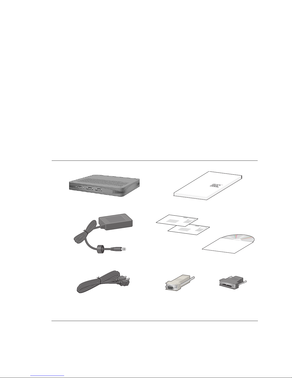
The following items are shipped with this product.
Figure 1 Items Shipped with the 1001, 1002, and 1004 Router
1001, 1002, or 1004 router (1004 shown)
Quick start guide
Power supply for 1002 and 1004 - 1001 power supply plugs
directly into an AC outlet
Warranty and registration cards and product docum en ta tion CD
ROM
AC power cord Female DB-9 to RJ-45 adapter (left ) and male DB-25 to
RJ-45 modem adapter (right)
Page 4
4 Quick Start Guide: 1000-Series Routers Ta sman Networks
W all-Mounting Option
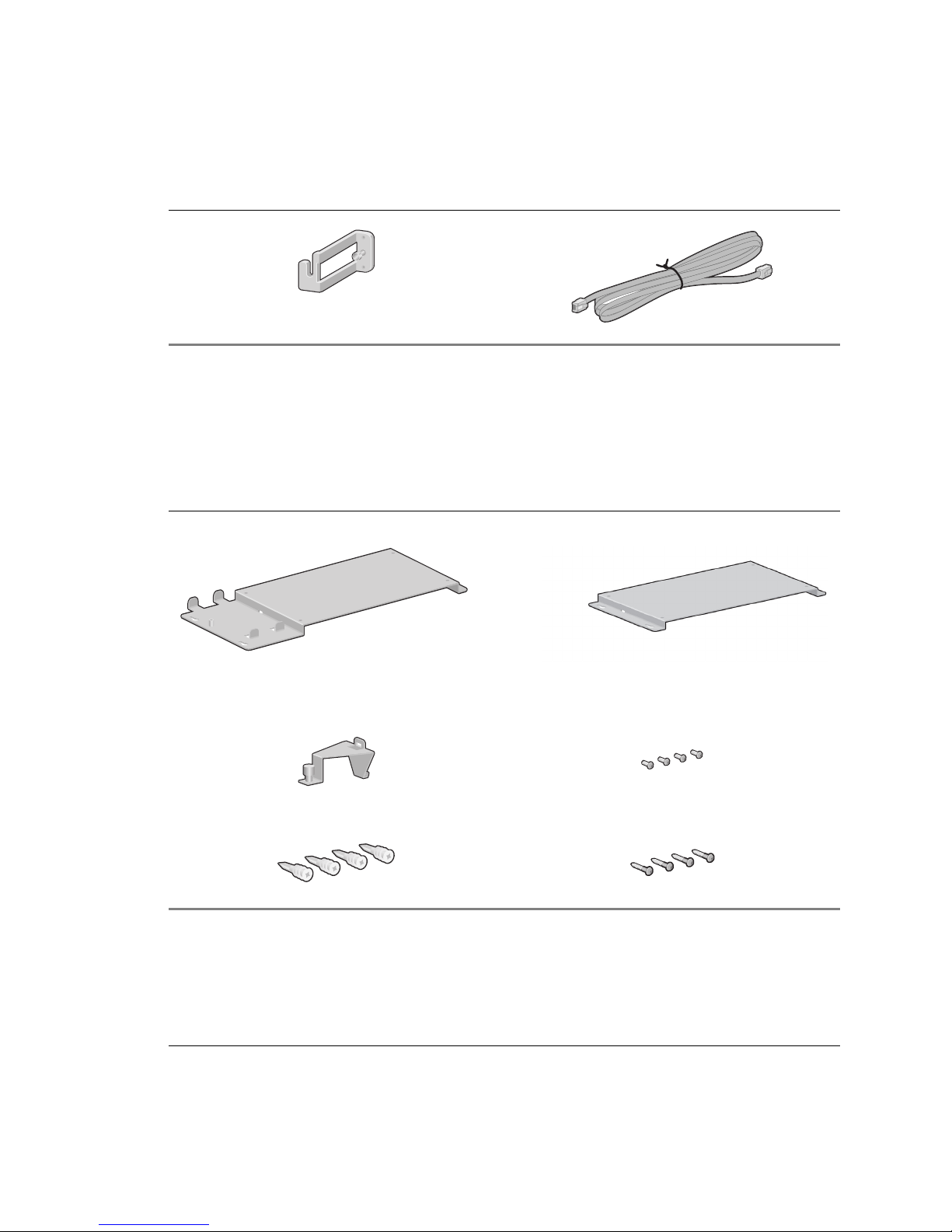
An optional wall-m ounting assembly is available for mounting the 1001, 1002, and 1004 router on a vertical surface.
The wall-mount components are shipped in the same box with the 1001, 1002, and 1004 router and are shown in the
following figure.
Figure 2 Wall-Mount Components
DC power cable retainer bracket
Console cable
Wall-mount brackets
Power supply strap
Router to wall-mount brac ke t scre w s: (4) 4-40 x .250 inch
Phillips pan head
Hollow wall anchors Wall-mount screws: (4) 6 x 1 inch Phillips pan head
1002 and 1004
1001
Page 5
Tasman Networks Quick Start Guide: 1000-Series Routers 5
Rack-Mounting Op tion
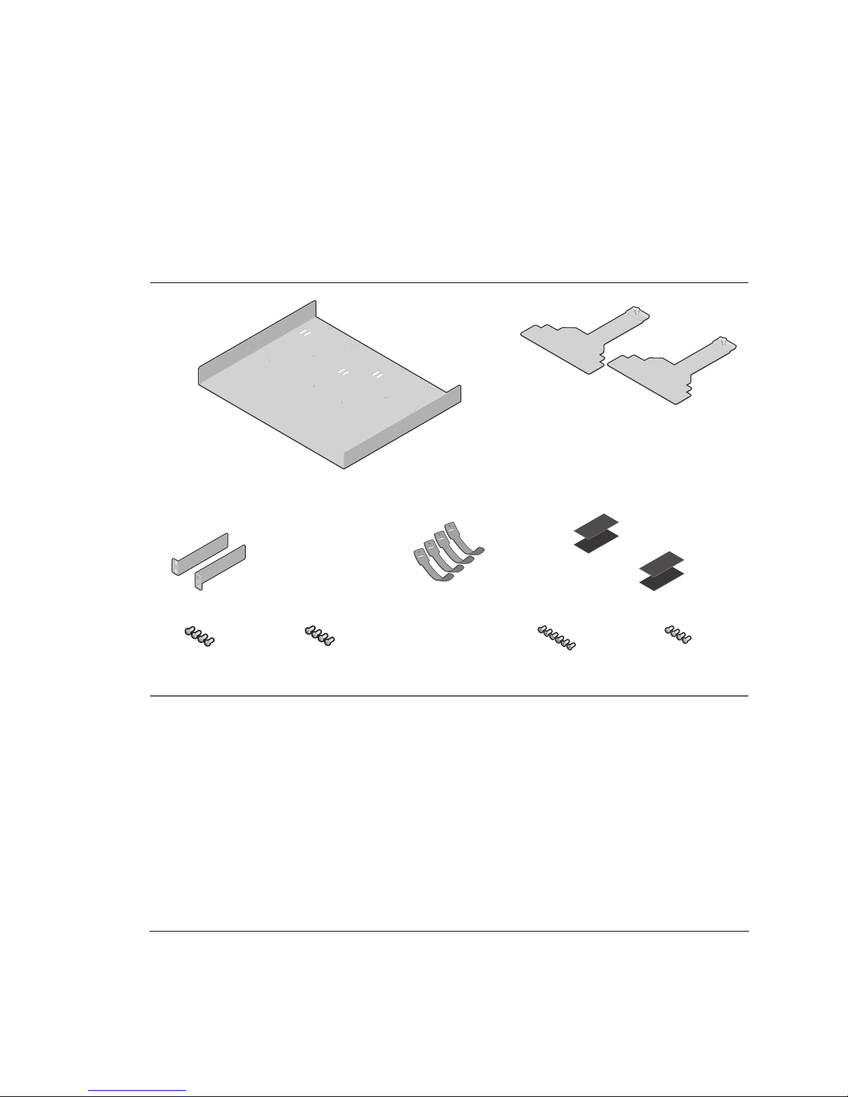
An optional rack-mountin g t r ay is a vail ab le for insta lli ng th e 10 02 and 10 04 ro ute r in a n eq uip m ent ra ck. The fo llo wing
items are shipped in a separate carton:
Figure 3 Rack-Mount Components
(2) Mounting Brackets
(4) Velcro Tie Wraps
(2 sets) Velcro Mounting Pads
(4) 10-24 x .5 Phil lips
Pan Head Screws for
Equipment Rack
(4) 12-32 x .5 Phil lips
Pan Head Screws for
Equipment Rack
(6) 6-32 x .25 Phillips
Flat Head Mounting
Bracket Screws
(4) 4-40 x .25 Phillips
Pan Head Rack Car riage
Screws
Rack Tray
(2) Rack Carriage
Assemblies
Page 6
6 Quick Start Guide: 1000-Series Routers Ta sman Networks
Additional Cables
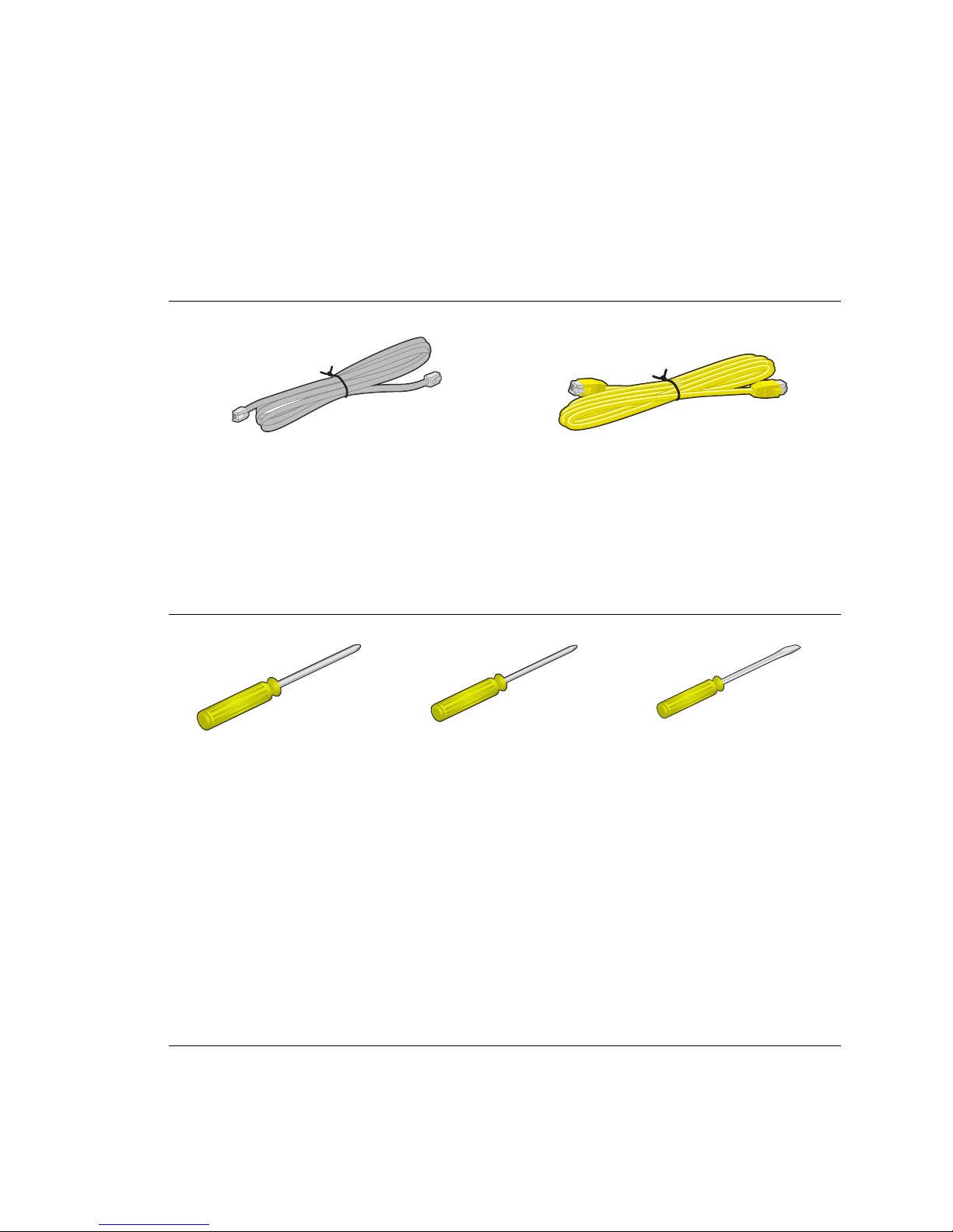
The following additional cables are required for installing the 1001, 1002, and 1004.
Figure 4 Additional Cables Re quired
T ools Required
The following tools are required for installing the 1001, 1002, and 1004.
Figure 5 Tools Required for Installation
Installation Site
The 1001, 1002, and 1004 is designed to be installed in an equipment rack; on a vertical surface; or on a flat, stable
surface. The installation site should provide ample room for connecting cables and should not be subject to extreme
temperature shifts. The router should be located in close proximity to all relevant telecommunication ports.
One or two RJ-45, male/male, category 5, twisted-pair cable
(Ethernet LAN connection)
One to two RJ-48C, male/male, 26 AWG (minimum) category 5,
straight-through cable (WAN connection)
#2 Phillips screwdriver
#3 Phillips screwdriver
1/4 inch flat blade screwdriver
Page 7
Tasman Networks Quick Start Guide: 1000-Series Routers 7
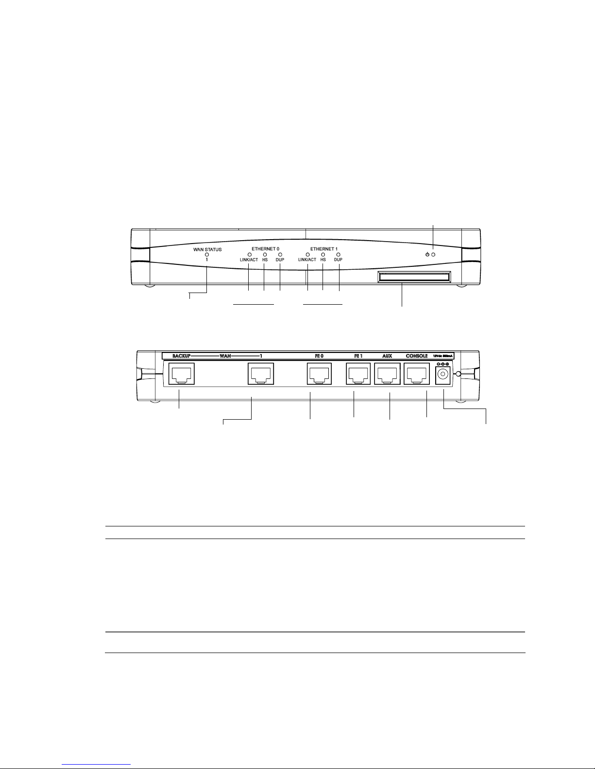
1001 Router Components
The following section i dentifies and describes t he 1001 router network ports and LEDs. The Model-1000 series routers
also supports a Web User Interface which can be used to configure basic operational and security features. For more
information on the Web UI, refer to the 1000-Series Router Web User Interface User Guide.
Figure 6 1001 Router Front Panel
Figure 7 1001 Router Back Panel
Back Panel Ports
Table 1 provides information about ports located on the rout er back panel.
Table 1 1001 Back-Panel Ports
port description
WAN 1 WAN connection port. These port s ac cept cables with RJ-48C conn ec tors. )
Backup WAN An ISDN backup option is supported in releases 8.3 and high e r. This option provides a backup if the primary
network connection is lost. This port accepts cables with RJ-45 connectors.
FE 0 - FE 1 Ethernet LAN connection ports. These ports accept cables with RJ-45 cable connectors.
AUX Reverse telnet connection. This port accept s a ca ble with an RJ-45 cable co nnector.
Console Console management port. This port accepts a ca ble with an RJ-45 cable connector.
DC power 12 VDC power connection. This port accepts the 2 mm power connector on the power supply cable that ships
with the 1001 router.
Ethernet 0 LEDs
Ethernet 1 LEDs
LINK/ACT HS
DUP
LINK/ACT HS
DUP
WAN Port
LED
Power LED
Compact Flash
Fast Ethernet
Port 0
Fast Ethernet
Port 1
AUX Port
12 VDC
Input Jack
WAN Por t
Backup WAN Port
Console
Port
Page 8

8 Quick Start Guide: 1000-Series Routers Ta sman Networks
Front Panel LEDs
The Tasman Networks 1001 router front-panel LEDs indicate real-time unit status. Table 2 provides inf ormation about
how to interpret the LED states. For more detailed LED information and troubleshooting tips, refer to the 1000-Series
Installation Guide.
Table 2 1001 Router LEDs
LED description color
WAN Stat us Indicates tr affic activity on this inter f ace
Green = normal activity
Red = alarm state
Yellow = test mode
Ethernet 0/1
Link/Act
Indicates tr affic activi ty on this inte r f ace Green = link is operational
Blinking Yellow = either receiving or sending traff ic
Red = packet collisions
HS
Indicates traffic speed o n the interface Off = 10 Mbps
Green = 100 Mbps
Dup
Indicates the type of duplex mode Off = Half duplex
Green = Full duplex
Power
Indicates router power status Off = power off
Green = power on
Page 9
Tasman Networks Quick Start Guide: 1000-Series Routers 9
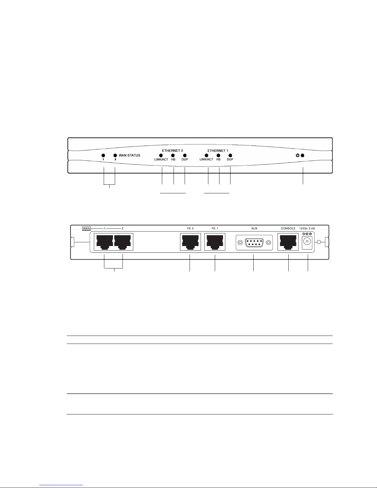
1002 Router Components
The following section i dentifies and describes t he 1002 router network ports and LEDs. The Model-1000 series routers
also supports a Web User Interface which can be used to configure basic operational and security features. For more
information on the Web UI, refer to the 1000-Series Router Web User Interface User Guide
Figure 8 1002 Router Front Panel
Figure 9 1002 Router Back Panel
Back Panel Ports
Table 3 provides information about ports located on the rout er back panel.
Table 3 1002 Back-Panel Ports
port description
WAN 1 - WAN 2 WAN connection port . T he se ports accept cables with RJ-4 8C connectors. If drop and insert is configured, then
ports 1 and 2 are reserved for tha t fe at ure.
FE 0 - FE 1 Ethernet LAN connection ports. These ports accept cables with RJ-45 cable connectors.
AUX Reverse telnet connection. This port accept s a ca ble with a male DB-9 conn ector.
Console Console management port. This port accepts a ca ble with an RJ-45 cable connector.
DC power 12 VDC power connection. This port accepts the 2 mm power connector on the power supply cable that ships
with the 1002 router.
WAN Port
LEDs 1-2
Ethernet 0 LEDs
Ethernet 1 LEDs
Power LED
LINK/ACT HS
DUP
LINK/ACT HS
DUP
WAN Ports 1 - 2 Fast Ethernet
Port 0
Fast Ethernet
Port 1
AUX Port
Console
Port
12 VDC
Input Jack
Page 10

10 Quick Start Guide: 1000-Series Routers Tasman Networks
Front Panel LEDs
The Tasman Networks 1002 router front-panel LEDs indicate real-time unit status. Table 4 provides inf ormation about
how to interpret the LED states. For more detailed LED information and troubleshooting tips, refer to the 1001, 10 02 ,
and 1004 Installat ion Guide.
Table 4 1002 Router LEDs
LED description color
WAN Status 1-2 Indicates traffic activ ity on this int erface
Green = normal activity
Red = alarm state
Yellow = test mode
Ethernet 0/1
Link/Act
Indicates tr affic activi ty on this inte r f ace Green = link is operational
Blinking Yellow = either receiving or sending traff ic
Red = packet collisions
HS
Indicates traffic speed o n the interface Off = 10 Mbps
Green = 100 Mbps
Dup
Indicates the type of duplex mode Off = Half duplex
Green = Full duplex
Power
Indicates router power status Off = power off
Green = power on
Page 11
Tasman Networks Quick Start Guide: 1000-Series Routers 11
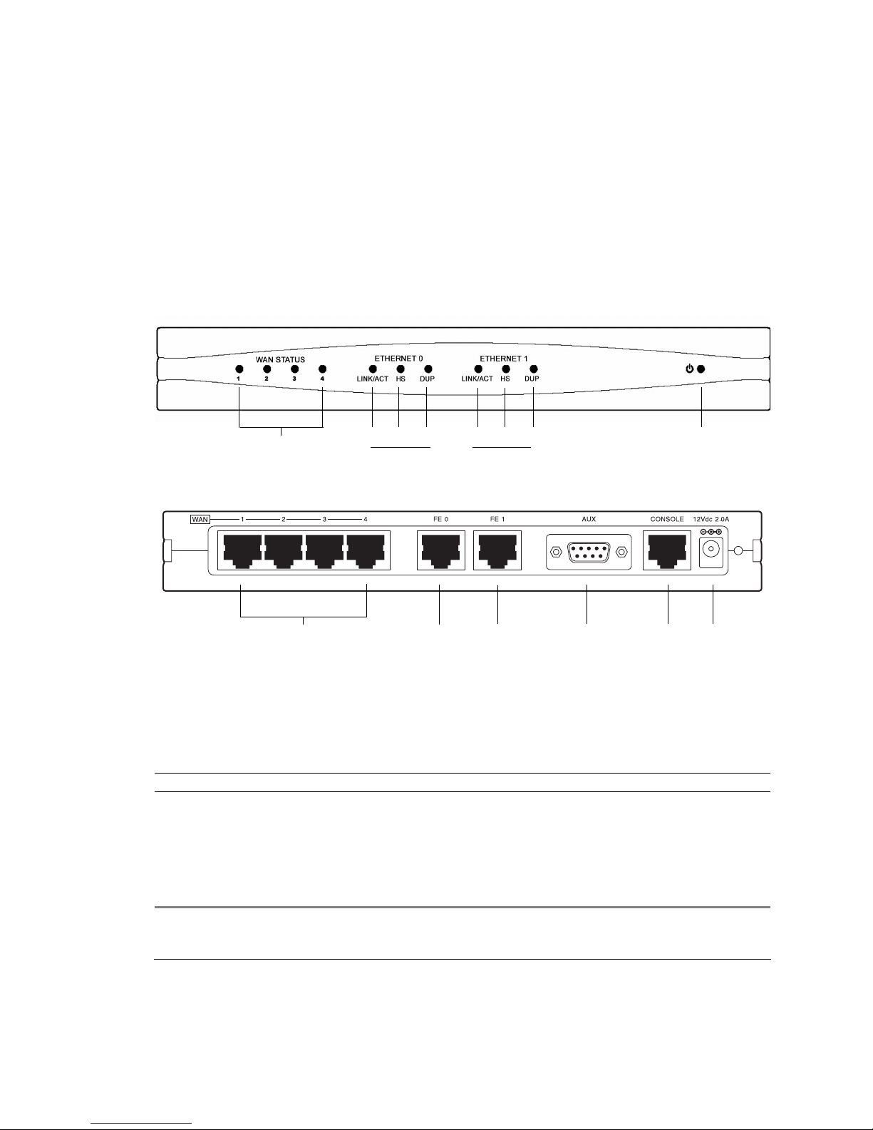
1004 Router Components
The following section identifies and describes the 1004router network ports and LEDs. The Model-1000 series routers
also supports a Web User Interface which can be used to configure basic operational and security features. For more
information on the Web UI, refer to the 1000-Series Router Web User Interface User Guide
Figure 10 1004 Router Front Panel
Figure 11 1004 Router Back Panel
Back Panel Ports
Table 3 provides information about ports located on the rout er back panel.
Table 5 1004 Back-Panel Ports
port description
WAN 1 - WAN 4 WAN connection port . T he se ports accept cables with RJ-4 8C connectors. If drop and insert is configured, then
ports 1 and 2 are reserved for tha t fe at ure.
FE 0 - FE 1 Ethernet LAN connection ports. These ports accept cables with RJ-45 cable connectors.
AUX Reverse telnet connection. This port accept s a ca ble with a male DB-9 conn ector.
Console Console management port. This port accepts a ca ble with an RJ-45 cable connector.
DC power 12 VDC power connection. This port accepts the 2 mm power connector on the power supply cable that ships
with the 1004 router.
WAN Port
LEDs 1-4
Ethernet 0 LEDs
Ethernet 1 LEDs
Power LED
LINK/ACT HS
DUP
LINK/ACT HS
DUP
WAN Ports 1 - 4 Fast Ethern et
Port 0
Fast Ethernet
Port 1
AUX Port
Console
Port
12 VDC
Input Jack
Page 12

12 Quick Start Guide: 1000-Series Routers Tasman Networks
Front Panel LEDs
The Tasman Networks 1004 router front-panel LEDs indicate real-time unit status. Table 4 provides inf ormation about
how to interpret the LED states. For more detailed LED information and troubleshooting tips, refer to the 1001, 1002,
and 1004 Installat ion Guide.
Table 6 1004 Router LEDs
LED description color
WAN Status 1-4 Indicates traffic activ ity on this int erface
Green = normal activity
Red = alarm state
Yellow = test mode
Ethernet 0/1
Link/Act
Indicates tr affic activi ty on this inte r f ace Green = link is operational
Blinking Yellow = either receiving or sending traff ic
Red = packet collisions
HS
Indicates traffic speed o n the interface Off = 10 Mbps
Green = 100 Mbps
Dup
Indicates the type of duplex mode Off = Half duplex
Green = Full duplex
Power
Indicates router power status Off = power off
Green = power on
Page 13
Tasman Networks Quick Start Guide: 1000-Series Routers 13
Installing the 1001, 1002, and 1004 Router
The 1001, 1002, and 1004 router can be installed on a table top, in a Telco equipment rack (using the optional rackmounting tray), or on a vertical surfac e (using the optional wall-mounting assembly). The router shi ps with a Console
cable. You will need to obtain additional cables for your specific application. Refer to Figure 4 for more information.
T able T op Installation
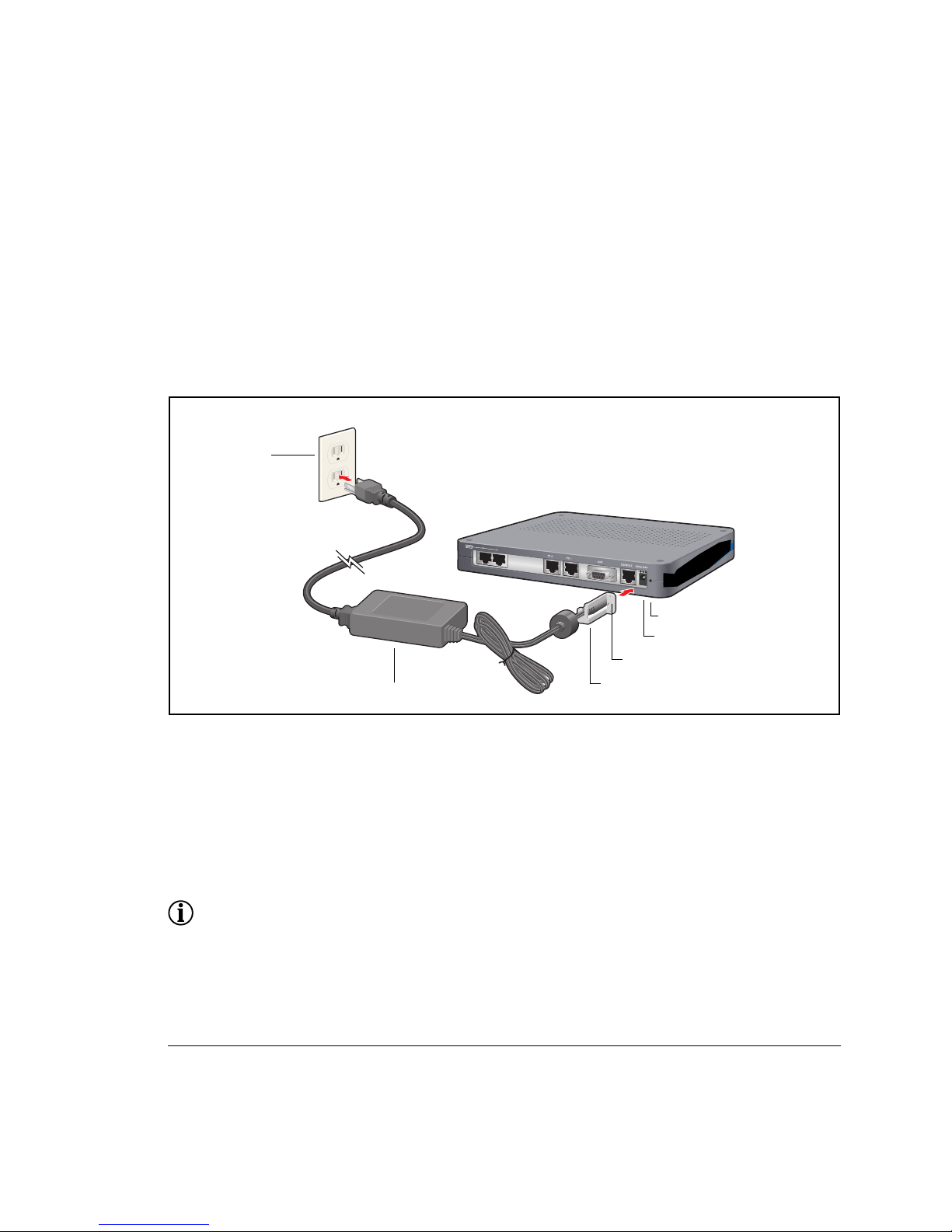
Figure 12 Table Top Installation
To install the 1001, 1002, and 1004 router for operation on a table top, follow this procedure. Refer to Figure 12 which
shows a Model 1002.
1 Place the router on t he table surface.
2 Attach the cable retainer to the DC power cord behind the molded strain relief on the cable.
3 Insert the DC power cable jack into the 12 VDC port on the back of the router.
4 Engage and secure the captive screw on the cable retainer in the threaded hole adjace nt to the DC input jack on the
router.
5 Connect the appropriate ends of the AC power cord to the power supply and a 110/120 VAC outlet.
NOTE: Ensure that cables are routed out of the way of foot traffic.
110/120 VAC Outlet
Cable Retainer Bracket
Power Supply
(for 1002 & 1004)
Captive Screw
Threaded Hole
12 VDC Port
Page 14
14 Quick Start Guide: 1000-Series Routers Tasman Networks
W all-Mount Installation
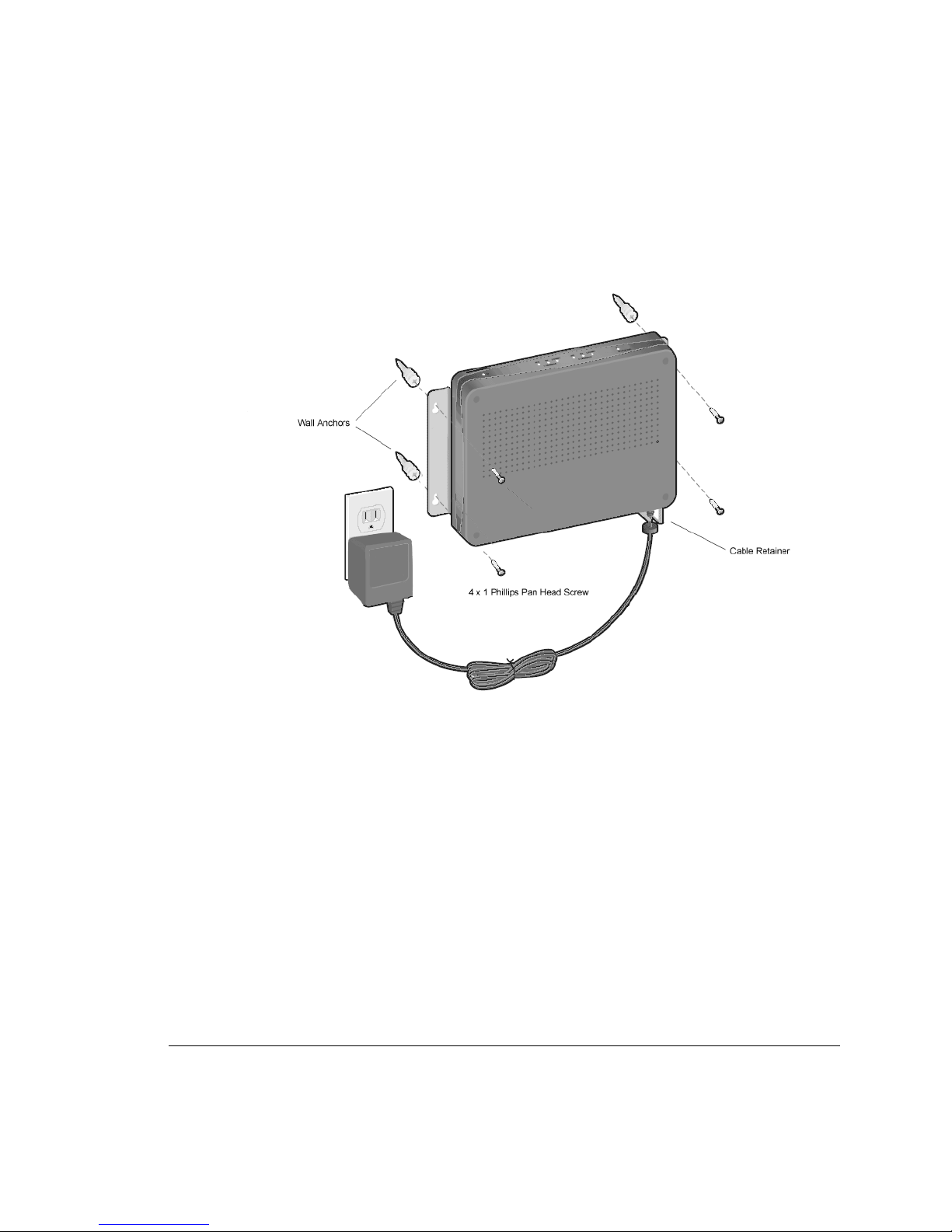
Figure 13 Wall Mounting the 1001 Router
Page 15
Tasman Networks Quick Start Guide: 1000-Series Routers 15
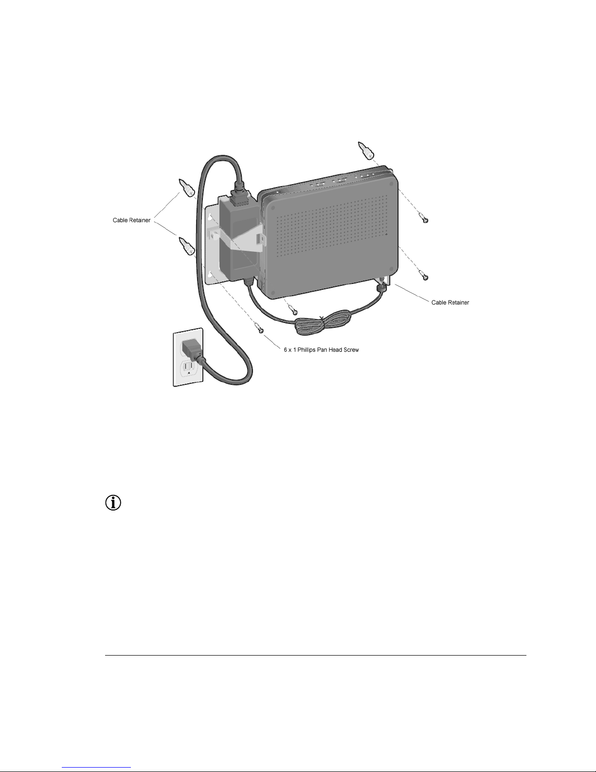
Figure 14 Wall Mounting the 1002 and 1004 Router
Follow this proced ure to mount the Tasman Networks 1001, 1002 , and 1004 router on a vertical surface. Refer to
Figure 14.
1 Attach the router to the wall mo unt bracket using the four (provided) Phillips pan head 4-40 x .250 inch screws.
Ensure that the router is oriented in a manner that allows the LEDs to be visible.
2 Attach the assembly with the mounted router to the wall surface using the four (provided) 6 x 1 inch (for 1002 and
1004) screws or 4 x 1 inch scre ws (for 1001) and hollow wall plastic anchors.
NOTE: T he provided hollow wall anchors are not designed for installation in hard walls. These anchors should only be
installed in a sheet rock (gyps u m wall board) wall.
3 Fit the AC strap over the power su pply and then place the power supply on t he wall mount bracket within the fou r
locating tabs.
4 Engage and tighten the AC strap captive screw to secure the power supply to the wall mount assembly.
5 Attach the cable retainer to the DC power cord behind the molded strain relief on the cable.
6 Insert the DC power cable jack into the 12 VDC port on the back of the router.
7 Engage and secure the captive screw on the cable retainer in the threaded hole adjace nt to the DC input jack on the
router.
8 Connect the appropriate ends of the AC cord to the secu red power supply and a 110/120 VAC outlet.
Page 16
16 Quick Start Guide: 1000-Series Routers Tasman Networks
Rack-Mount Installation
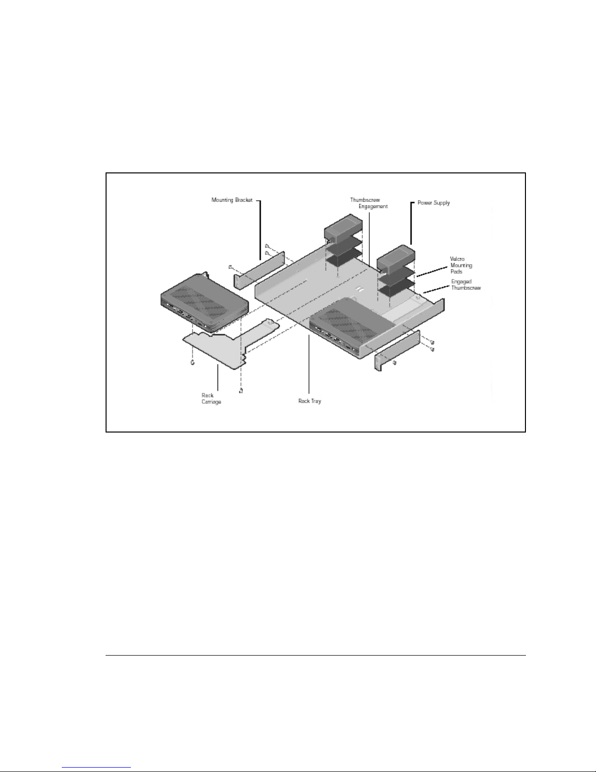
Figure 15 Rack Mounting the 1002 and 1004 Router
Follow this procedure to in stall the Tasman Networks 1002 and 1004 router in an equipmen t rack u sing th e option al rack
tray assembly. Refer to Figure 15.
1 Determine the mounting position for the rack tray in the equipment rack (front or mid-mount). Attach the mounting
brackets using the six provided 6-32 x .25 inch flat head Phillips screws. Use two screws for the rear bracket holes
and one screw for the front upper hole. (T he bottom front hole on each bracke t is not used.)
2 Attach the router to the rack carriage using two of the four provided Phillips pan head 4-40 x .25 inch screws.
3 Attach mating Velcro mounting pads to the rack tray and the bottom of the power supply, and then attach the power
supply to the rack tray.
4 Attach the cable retainer bracket to the DC power cord just behind the molded strain relief on the cord.
5 Insert the jack connector on th e DC power cord into the 12 VD C p ort on the back of the router.
6 Engage the captive screw on the cable retainer bracket into the threaded hole adjacent to the DC input jack on the
router. Tighten the captive screw.
7 Slide the mounted router and rack carriage onto the rack tray and engage the thumbscrew on the rack carriage into
the hole provided near the back edge of the rack tray. Tighten the thumbscrew.
8 Connect the network cables to the router ports and roughly dress the cables.
Page 17
Tasman Networks Quick Start Guide: 1000-Series Routers 17
9 Position the populated rack tray in the equipment rack .
10 Secure the rack tray to the equipment rack with ei ther set of the four provided screws. (Select the screw set that is
compatible with the equipme nt rack hole threa ds.)
11 Complete the cable dressing. Coil the excess power cord and secure it on the tray behind the router using the
provided Velcro tie wraps.
12 Plug the AC power cord into a standard 110/220 VAC outlet.
Network Connections
The following sections describe how to connect vari ous network cables to the r outer.
Connecting the Ethernet Cable
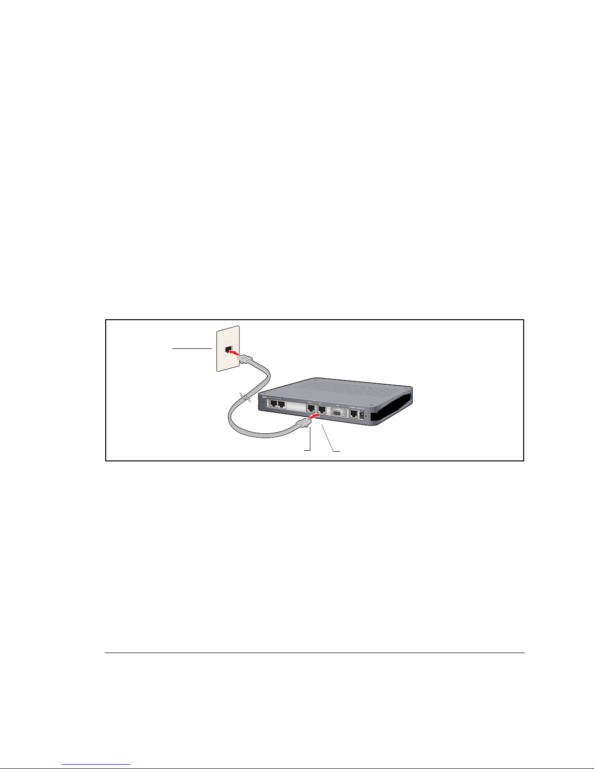
Figure 16 Connecting the Ethernet Cable
Follow this procedure to connect the 1001, 1002, and 1004 to an Ethernet LAN network. Refer to Figure 16.
1 Connect the RJ-45 connector of a category 5 rated Ethe rnet cable to either the E thernet 0 or Ethernet 1 port.
2 Connect the other end of the Ethernet cable to the L AN port.
Make sure that the cable connect ors are l ocked and secure in the ports.
For cable pinout information, refer to Appendix A in the 1001, 1002, and 1004 Install ation Guide.
Ethernet LAN Port
Fast Ethernet Port 0
Fast Ethernet Port 1
Page 18
18 Quick Start Guide: 1000-Series Routers Tasman Networks
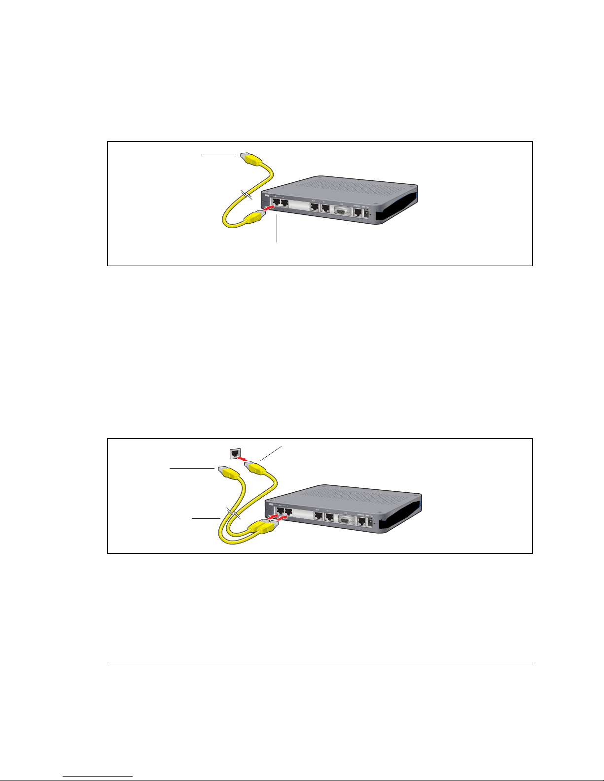
Figure17 Connecting the WAN Cable
Follow this procedure to connect a WAN port to the network. Refer to Figure 17.
1 Connect the RJ-48C co nnector of a WAN cable to an active license-enabled WAN port.
2 Connect the other end of the WAN cable to the service provider’s demarcation point.
Make sure that the cable connect ors are l ocked and secure in the ports.
For cable pinout information, refer to Appendix A in the 1001, 1002, and 1004 Router Installation Guide.
Connecting Cables for Drop and Insert Multiplexing
The 1002 and 1004 router can be used to connect a PBX to a carrier facility. If this mode is used, the PBX is connected
to WAN port 1 and the DS0s are mapped to the ca rrie r fac ilit y o n WAN port 2. To establish drop a nd in sert con nectiv ity,
use two 26 AWG (minimum) category 5, twisted-pair cables with RJ 48C connectors.
Figure 1 8 Connecting Drop and Insert Cables
To connect drop and insert cables, follow this procedure. Refer to Figure 18.
1 Insert the RJ-48C connector of one end of one WAN cable in WAN port 1 on the router.
2 Connect the other end of this cable to the local PBX port.
3 Insert the connector on one end of the second cable to WAN port 2 on the router.
4 Connect the other end of this cable to the service provider’s demarcation point.
Connect to Service
Provider’s Demarcation Point
WAN Port 1
Connect to Service Provider’s
Demarcation Point
Connect to the Local PBX Port
RJ-48C WAN Cables
Page 19
Tasman Networks Quick Start Guide: 1000-Series Routers 19
For information about configuring drop and insert, refer to the 1001, 1002, and 10 04 Installation Guide and the
Command Reference Guide.
Management Interface
To configure and manage the 1001, 1002, and 1004 router using the Tasman Networks command line interface (CLI), an
operator console must be connected to the router. Refer to “Connecting the Ethernet Cable” on page 17 for connection
details. The operator cons ole can be connected with either a local or a remote connection. It is also possi ble to telnet to
the 1001, 1002, and 1004 router once an I P address has been configured on an Ethernet port.
Local Management
To configure, operate, and manage the 1001, 1002, and 1004 locally, connect the Console port to a workstation or a
terminal (VT-100 or equivalent) that is r unning terminal emulation software.
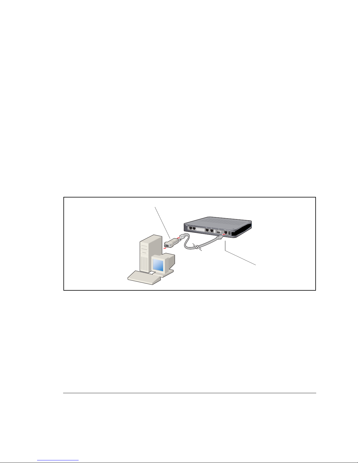
Figure 19 Connecting the Console Cabl e
Follow this procedure to connect th e Console cable: Refer to Figure 19.
1 Connect the Console cable to the Console port on the router.
2 Connect the other end of the Co nsole cable to the RJ-45 end of the DB-9 to RJ-45 modular adapt e r.
3 Connect the DB-9 end of the modular adapter to a management terminal or workst ation.
Remote Manageme nt
A modem can be connected to th e Console port and used to configure, operate, and manage the 1001, 1002, and 1004
remotely.
RJ-45 to DB-9 Adapter
Console Port
Page 20
20 Quick Start Guide: 1000-Series Routers Tasman Networks
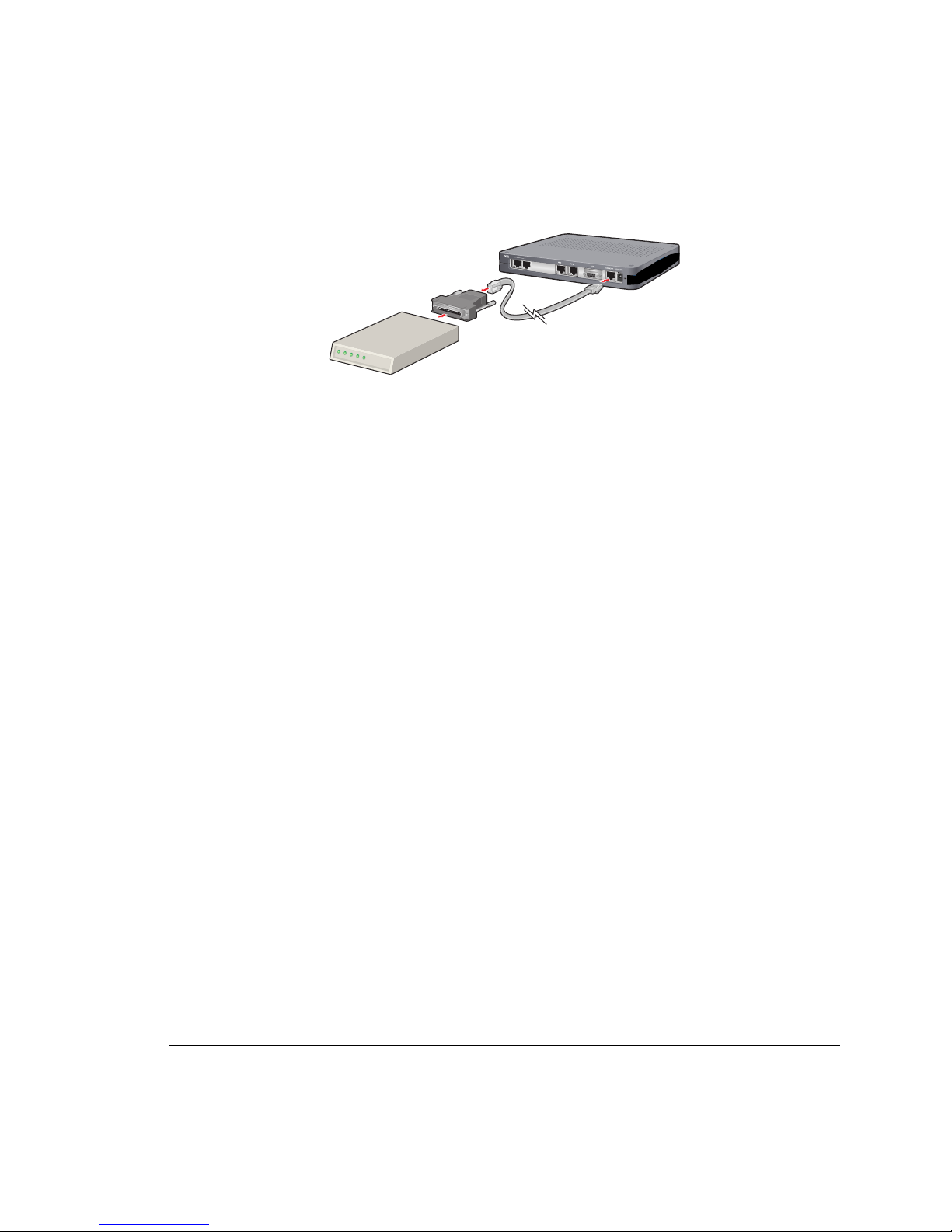
Figure 20 Connecting the 1001, 1002, and 1004 to a Mod em
Follow this procedure to connect th e 1001, 1002, and 10 04 to a modem. Refer to Figure 20.
1 Connect the male end of the DB-25 adapter to the female DB-25 port on the modem.
2 Connect o ne end of a supplied RJ-45 cable to the RJ-45 por t in the DB-25 adapter.
3 Connect the other end of the RJ-4 5 cable to the Console p or t on the 1001, 1002, and 1004.
4 Configure the modem for 9600 bps, 8 data bits, 1 stop bit, no parity, and XON/XOFF flow control. Refer to your
modem documentation, if necessary. Consult the Tasman Networks Support website for additional configuration
information.
If a workstation is us e d for th e r em ote m a na ge m e nt c on s ol e, use VT -100 terminal emulation software or equivalent,
and configure the software as specified for modems.
Configuring the Router
The following sections introduce commands that you can use to log in as the system admi nistrator, choose a host name,
change the password, set the system date and time, enter an Ethernet IP address, establish a default route, switch modes,
and save the configuration.
Logging In
Login: tasman
Password: tasmannet
Choosing a Host Name
Tasman Networks# configure term
Tasman Networks/configure# hostname ISP_name
ISP_name/configure#
Changing the Password
Tasman Networks# password
name: tasman
old password: tasmannet
new password: new_pass
re-enter password: new_pass
Page 21

Tasman Networks Quick Start Guide: 1000-Series Routers 21
Passwords are case-sensitive and must be a minimum of three to a maximum of eight ch aract ers. For future reference,
make a note of the password that you use.
Changing the Administrator Account Name
You can change the administrator login name (Level 1 access) to a user-specified name. The defaul t is Tasman
Networks.
The following commands change the administrator account name to Greg:
Tasman Networks# configure term
Tasman Networks/configure# admin_name Greg
Configuring the Date and T ime
Tasman Networks# configure term
Tasman Networks/configure# date - 0 0 mo 3 d 19 y 2000 h 14 mi 40 s 35
The first portion of this command, date - 0 0, establishes offset from GMT. The minus sign inputs offset direction, and
the two numbers input offset hours and minutes. The second portion of this command, mo 3 d 19 y 2000 h 14 mi 40 s
35, inputs the local month, day, year, hour, minute, and second.
Configuring an Ethernet IP Address and Subnet Mask
Tasman Networks# configure term
Tasman Networks/configure# interface ethernet 0
Tasman Networks/configure/interface/ethernet 0# ip address 10.1.100.28 255.255.255.0
Configuring a Default Rout e
Tasman Networks/configure# ip route 0.0.0.0 0 10.1.100.xxx
In the above example, “xxx ” represents the gateway.
Switching Routing/IPMux Modes
To switch from dynamic routing mode to IPMux mode, issue the following command:
Tasman Networks/configure# no system routing
To switch from IPMux back to dynamic routing mode, issue t he following command:
Tasman Networks/configure# system routing
Page 22

Interface Port Configuration
The following are examples of T1, CT3, and DS3 interface configurations. To scroll through the options available at any
command prompt, press the Tab key. For descriptions of the options available at any command prompt, type help and
press Enter.
E1 Interface
Router# configure term
Router/configure# module e1 4
Router/configure/module/e 1 4# clock_source line
Router/configure/module/e 1 4# framing crc
Router/configure/module/e 1 4# exit 2
Router/configure# cabletype monitor_port 1 twisted_pair
Router/configure# module e1 4
Router/configure/module/e 1 4# linecode hdb3
Router/configure/module/e 1 4# yellow_alarm gen_det
Router/configure/module/e 1 4# exit 3
T1 Interface
Router# configure term
Router/configure# module t1 4
Router/configure/module/t1 4# clock_source line
Router/configure/module/t1 4# framing esf
Router/configure/module/t1 4# linecode b8zs
Router/configure/module/t1 4# yellow_alarm gen_det
Router/configure/module/t1 4# exit 3
Page 23

Tasman Networks Quick Start Guide: 1000-Series Routers 23
Bundle Configuration
Tasman systems support PPP, MLPPP, FR, MFR, and Cisco-compatible HDLC for WAN data transmission.
NOTE: Bundle names cannot exceed eight characters.
E1/PPP Bundle
Router# configure term
Router/configure# interface bundle HongKong
Router/configure/interface/bundle HongKong# link e1 4
Router/configure/interface/bundle HongKong# encapsulation ppp
Router/configure/interface/bundle HongKong# ip address 199.1.1.1 255.255.255.0
Router/configure/interface/bundle HongKong# exit 3
NxE1/MLPPP Bundle
Router# configure term
Router/configure# interface bundle Paris
Router/configure/interface/bundle Paris# link e1 5-8
Router/configure/interface/bundle Paris# encapsulation ppp
Router/configure/interface/bundle Paris# ip address 200.1.1.1 255.255.255.0
Router/configure/interface/bundle Paris# exit 3
NxE1/MFR Bundle
Router# configure term
Router/configure# interface bundle Madrid
Router/configure/interface/bundle Madrid# link e1 3-4
Router/configure/interface/bundle Madrid# encapsulation fr
Router/configure/interface/bundle Madrid# fr
Router/configure/interface/bundle Madrid/fr# intf_type dce
Router/configure/interface/bundle Madrid/fr# lmi
Router/configure/interface/b undle Madrid/fr/lmi# keep alive 12
Router/configure/interface/b undle Madrid/fr/lmi# exit
Router/configure/interface/bundle Madrid/fr# pvc 16
Router/configure/interface/ bundle Madrid/fr/pvc 16 # shaping cir 1920000
Router/configure/interface/ bundle Madrid/fr/pvc 16 # exit
Router/configure/interface/bundle Madrid/fr# enable interface
Router/configure/interface/bundle Madrid/fr# exit 4
Fractional E1/Cisco-compatible HDLC Bundle
Router# configure term
Router/configure# interface bundle London
Router/configure/interface/bundle London# link e1 3:1-6
Page 24

24 Quick Start Guide: 1000-Series Routers Tasman Networks
Router/configure/interface/bundle London# encapsulation hdlc
Router/configure/interface/bundle London# hdlc keepalive 20
Router/configure/interface/bundle London# ip address 192.168.2.1 255.255.255.0
Router/configure/interface/bundle London# ex it 3
Fractional T1/Cisco-compatible HDLC Bundle
Router# configure term
Router/configure# interface bundle Denver
Router/configure/interface/bundle Denver# link t1 3:1-6
Router/configure/interface/bundle Denver# encap sulation h dlc
Router/configure/interface/bundle Denver# hdlc keepalive 20
Router/configure/interface/bundle Denver# ip address 192.1 68.2.1 255.255. 255.0
Router/configure/interface/bundle Denver# exit 3
T1/PPP Bundle
Router# configure term
Router/configure# interface bundle Boston
Router/configure/interface/bundle Boston# link t1 4
Router/configure/interface/bundle Boston# encapsulation ppp
Router/configure/interface/bundle Boston# ip address 199.1.1.1 255.255.255.0
Router/configure/interface/bundle Boston# exit 3
NxT1/MLPPP Bundle
Router# configure term
Router/configure# interface bundle Houston
Router/configure/interface/b undle Houston# link ct 3 1 5-8
Router/configure/interface/b undle Houston# encapsulation ppp
Router/configure/interface/b undle Houston# ip address 200.1.1.1 255.255.255.0
Router/configure/interface/b undle Houston# exit 3
The following are examples of frame relay and PPP bundles configured for DS3 WAN transmission.
NxT1/MFR Bundle
Router# configure term
Router/configure# interface bundle Seattle
Router/configure/interface/b undle Seattle# link t1 3-4
Router/configure/interface/b undle Seattle# encapsulation fr
Router/configure/interface/b undle Seattle# fr
Router/configure/interface/bund le Seattle/fr# intf_type dce
Router/configure/interface/bund le Seattle/fr# lmi
Router/configure/interface/bundle Seattle/fr/lmi# keepalive 12
Router/configure/interface/bundle Seattle/fr/lmi# exit
Router/configure/interface/bund le Seattle/fr# pvc 16
Page 25

Tasman Networks Quick Start Guide: 1000-Series Routers 25
Router/configure/interface/b undle Seattle/fr/pvc 16# shaping cir 3072000 bcmax 30720000 bcmin 1536000
Router/configure/interface/b undle Seattle/fr/pvc 16# exit
Router/configure/interface/bund le Seattle/fr# enable interface
Router/configure/interface/bund le Seattle/fr# exit 4
Frame Relay Bundle
Router# configure term
Router/configure# interface bundle Rome
Router/configure/ interface/bundle Rome# link e1 3
Router/configure/ interface/bundle Rome# encapsulation fr
Router/configure/ interface/bundle Rome# fr
Router/configure/ interface/bundle Rome/fr# intf_type dce
Router/configure/ interface/bundle Rome/fr# lmi
Router/configure/ interface/bundle Rome/fr/lmi# keepalive 12
Router/configure/ interface/bundle Rome/fr/lmi# exit
Router/configure/ interface/bundle Rome/fr# pvc 16
Router/conf igure/ interfa ce/bundle Rome/fr/pvc 16# shaping cir 2048000
Router/conf igure/ interfa ce/bundle Rome/fr/pvc 16# exit
Router/configure/ interface/bundle Rome/fr# enable interface
Router/configure/ interface/bundle Rome/fr# exit 4
Routing Configuration
Tasman products support RIP, OSPF, and BGP4 routing protocols.
RIP
Configuring RIP for Ethernet 0 and WAN 1 interfaces.
Router# configure terminal
Router/configure# router rip
Router/configure/router rip# interface ethernet0
Router/configure/router rip/interface ethernet0# exit
Router/configure/router rip# interface wan1
Router/configure/router rip/interface wan1# exit 3
OSPF
Configuring OSPF between a LAN and a WAN over multiple CT3 links running MLPPP.
Router# configure terminal
Router/configure# interface ethernet 0
Router/configure/interface/ethernet 0# ip address 10.10.10.1 24
Router/configure/interface/ethernet 0# exit 2
Router/configure# interface bundle Dallas
Page 26

26 Quick Start Guide: 1000-Series Routers Tasman Networks
Router/configure/interface/bundle Dallas# link ct3 1 1-10
Router/configure/interface/bundle Dallas# encapsulation ppp
Router/configure/interface/bundle Dallas# ip address 20.20.20.1 24
Router/configure/interface/bundle Dallas# exit 2
Router/configure# router routerid 10.10.10.1
Router/configure# router ospf
Router/configure/router/ospf# area 760
Router/configure/router/ospf/area 760# exit
Router/configure/router/ospf# interface Dallas area_id 760
Router/configure/router/ospf/interface Dallas# cost 10
Router/configure/router/ospf/interface Dallas# exit
Router/configure/router/ospf# interface ethernet0 area_id 760
Router/configure/router/ospf/interface ethernet0# cost 10
Router/configure/router/ospf/interface ethernet0# priority 0
Router/configure/router/ospf/interface ethernet0# exit 3
BGP4
Configuring EBGP between two different autonomous systems.
Router/configure# interface bundle Chicago
Router/configure/interface/bundle Chicago# link ct3 1 1-10
Router/configure/interface/bundle Chicago# encapsulation ppp
Router/configure/interface/bundle Chicago# ip ad dress 20.20.20.1 24
Router/configure/interface/bundle Chicago# exit
Router/configure# router bgp 10
Router/configure/route r/bgp 10# neighbor 20.20.20.2 20
Router/configure/router /bgp 10/neighbor 20.20.20.2 20# exit 3
Configuring IBGP between two neighbors in the same autonomous system.
Router/configure# interface ethernet 0
Router/configure/interface/ethernet 0# ip address 10.10.10.1 24
Router/configure/interface/ethernet 0# exit
Router/configure# router bgp 10
Router/configure/route r/bgp 10# neighbor 10.10.10.2 10
Router/configure/router /bgp 10/neighbor 10.10.10.2 10# exit 3
Redistributing static and connected routes.
Router/configure# ip route 9.9.0.0 255.255.0.0 10 .10.10.10
Router/configure# router bgp 10
Router/configure/route r/bgp 10# redistribute static
Router/configure/route r/bgp 10# redistribute connected
Router/configure/route r/bgp 10# exit 2
Page 27

Tasman Networks Quick Start Guide: 1000-Series Routers 27
Saving Configurations
Execute the following command to save new configurations to system memory.
Tasman Networks# write memory
NOTE: Before powering down the 100 1, 1002, and 1004, execute a write memory command to save th e router configuration.
Execute the following command to save new configurations to a network host. You must identify the host
name or IP address, the host directory that the file is being transferred to, and the new file name.
Tasman Networks# write network 10.1.100.149 /maindir/config01.txt
NOTE: When saving to a network host, the host di rectory and file name must alre ady exist.
About the
T asman Networks R outer Documentation
CD-ROM
This product ships with a CD that includes the following:
Tasman Networks Router Quick Start Guides
Tasman Networks Router Instal latio n G ui de s
Command Reference Guide
Router User Guide
Configuration Guide
Navigation
Upon inserting the Tasman Networks Router Documentation CD into your PC’s CD-ROM drive, a browser session is
initiated and the naviga tio n screen is d ispla y ed. Cli ck a link to o pe n a pdf version of the target documenta tion. If you do
not have Adobe Acrobat (version 4.0 or later) or Acrobat Reader installed on your PC, click the Adobe icon on the
navigation screen to downloa d a free Acrobat Reader application.
Printing Documents
1 Open the desired pdf document by clicking the document link in the CD navigation window.
2 Click the “Printer” icon on the Adobe Acrobat tool bar.
3 In the “Windows Print” dialog box, select a local default printer in the printers drop down selection box.
4 Click “OK.”
Page 28

28 Quick Start Guide: 1000-Series Routers Tasman Networks
Copyright
Copyright © 2002-2005, Tasman Networks All rights re served. No part of this documen t m ay b e reproduced in any form or by any
means without prior written autho rization from Tasman Networks
Tasman Networks reserves the right to revise this document without ob ligation to provide notification of suc h changes.
Tasman Networks provides this documentation without warranty expressed, implied, statutory, or otherwise, and specifically disclaims
any warranty of merchanta bi li ty or fit ne ss for a pa rti cu la r purpose. Tasman Networks may make improvements or change s in the
product(s) and/or the program(s) described in this documentation at any time.
Trademarks
Tasman Networks and the Tasman Networks corporate logo are trademarks of Tasman Networks All other trademarks appearing in this
guide are the exclusive property of their respect i ve owners.
Software Notice
Tasman Networks assumes no responsibility for product reliability, performance, or both if the us er m odifies the .CFG file. Full
responsibility for any performa nce issues resulting from modifica tions made to the .CFG file, by the user, is assumed by the user.
Documentation Feedback
The mission of Technical Publications at Tasman Networks is to provide quality documenta ti on th at enhances the user’s experience
with Tasman Networks products. We are constantly improving our guides and have a genuine interest in ensuring that our guide s are
easy to use and enable users to quickly find information they need. We invite you to be part of this process; please email your comments
regarding Tasman Networks product documentation or w eb cont e nt t o:
Corporate Policy
S tandard Warranty
Hardware
Tasman Networks, Inc. warrants that the Hardware sold here under shall be free of defects in work ma nship for a period of one (1) year
from the Date of Shipment. In the event that Tasman Networks receives notice f rom the Cust omer during the warranty pe rio d tha t any
Hardware does not confor m t o thi s warranty, Tasman Networks, shall, at its sole option , e it her repair or replace the non-co nforming
Hardware. If said notice is received within ninety (90) days of shipment from the Tasman Networks factory in San Jose, CA, such
replacement shall be “Next Busine ss D ay.” If said notice is received a fte r ni nety (90) days from shipping from Tasman Networks, the
Customer must ship the defective Hardware to Tasman Networks for repair. Such repair shall take no more than t en ( 1 0) b u sin ess days.
Cost of shipping to Tasman Networks shall be at the Customer’s expense. Cost of shipping the repaired unit to the Customer shall be at
Tasman Networks’ expense. Under the terms of an y such warranty, Hardware may be replaced with refurbished or new Hardware at
Tasman Networks’ option.
Page 29

Tasman Networks Quick Start Guide: 1000-Series Routers 29
Software
Tasman Networks, Inc. warrants that the media on which the Soft ware is recorded shall be free from defe ct s in m a te ria l and
workmanship under normal use for a period of ninety (90) days from the Date of Shipment. The Customer’s sole and e xclus ive remedy,
and Tasman Networks sole and exclusive liability, shall be replacement of the media in accordance with this limited warranty. The
Customer shall be entitl ed to free Software upgrades (bug fi xes and feature enhancem e nts not listed as separate cost options of the
Tasman price list) from the Tasman website for the first ninety (90) da ys after shipment from Tasman Networks.
T echnical Support
Online and email Technical Support is provided free of charge for a period of ninety (90) days from the Date of Shipment. Technical
Support is available onlin e a t th e Tasman Networks web sit e: ww w.tasmannetworks.com or by em ail at:
[email protected]. Technical Support provides the followi ng services:
Technical Support will assist the Customer in determining if prob le m s enc oun te re d w ith Tasman products are due to errors or
limitations in the current Tasman Networks opera ti ng syst em and advise the Customer on the availability of Software upd at es or
workarounds.
Technical Support will provide assistance to the Custome r re garding questions concerning th e installation of Software update s
and configuration questions arising from Software updat es.
Technical Support will work with the Customer to de velop and implement appropriate network config ura ti ons.
Procedures
A product may only be returne d w ith the prior written approval of Tasman Networks. Such ap proval shall reference a Retu rn Ma te r ial
Authorization (RMA) number issue d by aut hori z ed Tasman Networks Technical Support personnel. Transportation costs, if any,
incurred in connection with the return of a defective item to Tasman Networks shall be borne by the Customer. Transportation costs
incurred in connection with the re-delivery of a repaired or replaced item to the Customer shall be borne by Tasman Networks.
However, such costs shall be borne by the Customer if Tasman Networks reasonably determines that the product is not defec tiv e . If
Tasman Networks determines, in its sole discretion, that the allegedly defective product is not c ove re d by the terms of the warranty
provided hereunder, or that a warranty cla im is m ade aft er the warranty period, the cost of repair by Tasman Networks, including all
shipping expenses, shall be reimbursed by the Customer. Tasman Networks, shall have no liability with respect to data contained in any
system returned to Tasman Networks.
Exclusions
The foregoing warranties and remedies are for the Customer’s exclusive benefit and are non-transferable. Any and all warranties shall
be void regarding System compone nts t hat are damaged or rendered unserviceable by: (1) acts or omissions of non-Tasman Networks
personnel; (2) misuse, theft, vandalism, fire, water, or other peril; (3) alterat io ns of or additions to the System or any elem ent thereof
performed by personnel not cert ifi e d by Tasman Networks to perform such alt era t ion s and a ddi ti ons or (4) the Customer ’s failure to
meet environmental specifications.
Non-T asman Netw orks Products
In circumst ance s wh ere a pro duc t n ot ma nu fac tur ed o r c r eated by Tasman Networks is so ld by Tasman Networks hereu nde r t o comp lete
an order, the Customer’s sole remedy shall be pursuant to the original manufacturer’s/licensor’s warranty to the Customer, to the extent
permitted by the original manufa cturer/licensor.
Disclaimer of W arr anty
The limited warranti es referred to in paragraphs above shall be in lieu of all other wa rra nt ie s w hether expressed, implied, statutory, or
otherwise. Tasman Networks specifically disclaims any impli ed warra nties of merchantability or fitness for a pa rt ic ular purpose.
Page 30

30 Quick Start Guide: 1000-Series Routers Tasman Networks
Limitation of Liability
Tasman Networks, Inc. and its suppliers exclude themselves from any liability for any lost reve nue or profit, loss of business, loss of
information or data, or for special, indirect, consequential, incidental, or punitive damages of any kind caused out of or in connection
with the sale, installation, main tenance, use, performance, fai lu re, or interruption of its product s, even if Tasman Networks and its
authorized resellers have been adv ised of th e possibility of such damages. In no event shall Tasman Networks’ or its supplier’s total
liability to the Customer, whether in contract negligence, strict liability, tort or otherwise, exceed the price paid by the Customer. The
foregoing limitation s shall apply even if any reme dy provided herein shal l f ail its essential purpose.
Equipment Malfunction
In the event this equipment should fail to operate pr operly, disconnect the unit from the telephon e li ne and contact Tasman Technical
Support at the address and phone number listed in below. DO NOT DISASSEMBLE THIS EQUIPMENT. This equipment does not
contain any user-serviceable components. If the equipment is causing harm to the network, the telephone company may request that you
disconnect this equipment from the telephone network until the problem is resolved.
Contacting T asman Networks
Telephone 1-408-216-4700
Fax 1-408-216-4701
Mail Tasman Networks, Inc.
5400 Hellyer Avenue
San Jose, CA 95138
USA
Internet www.tasmannetworks.com
 Loading...