

Page 1

RGB MULTI-COLOR TAPE LIGHT
installation guide
January 2019
Customer Service: 800-445-6404
Design Services & Tech Support: 866-848-9094
www.TaskLighting.com
Page 2

RGB Tape Light
+–
+
+–
+
Wiring and Pairing Guide
T-C-RGB180 T-C-RGBWC-RF-Color
Dimming Components
Part Number Description and Use
T-C-RGB180
T-C-RGBWC-RF-Color
Tools Needed
Wire
Strippers
Chroma RGB Receiver. Allows you to individually control color settings and program into memory. Use
with T-C-RGBWC-RF-Color.
Chroma RGB wireless wall dimmer controller. Allows you to program up to 4 color settings or color eects
for 1 Zone. Use with T-C-RGB180 Receiver. Available in Almond (AL), Black (BK), Brown (BR), Gray (GR),
or White (WT)
Pliers Flat Head
Screwdriver
#1 Phillips
Screwdriver
#2 Phillips
Screwdriver
Product Legend
Female Barrel
Connector
T-FBC
36
Customer Service: 800.445.6404 • Design Services/Technical Support: 866.848.9094 • TaskLighting.com
Wire Nuts
Tape to Wire Connector
L-10MM-RGB-WSC
Page 3

Wiring Power Supply to Receiver Guide
Option 1: Using a Plug-in Power Supply
Provide an outlet for the Plug-in Power Supply
1. Remove terminal covers from each end
of Receiver.
4. Insert the Male Plug on the Power
Supply into the Female Barrel Connector.
2. Cut a length of connection wire to run
from the Power Supply to the Receiver
location. Strip 1/4" insulation from both
ends of connection wire, twist each wire,
and fold in half.
5. Loosen left side terminal screws on the
INPUT side of the Receiver, insert other
end of connection wire into terminals,
Red to (V+), Black to (V-); tighten screws.
Option 2: Using a Hardwired Power Supply
3. Loosen terminal screws on the Female
Barrel Connector included with Power
Supply. Insert one end of the wire into the
terminals, Red to (+), Black to (-); tighten
screws.
NOTE: Make sure the Black tab between
terminals covers both pins for Master
Receiver Setting.
1. Remove terminal covers from each end
of Receiver.
4. Strip 1/4" insulation from the other end
of connection wire, twist each wire, and
fold in half.
Customer Service: 800.445.6404 • Design Services/Technical Support: 866.848.9094 • TaskLighting.com
2. Cut a length of connection wire to
run from the Power Supply to Receiver.
(NOTE: Power Supply comes with 24" of
wire – add extra wire for desired length.)
5. Loosen terminal screws on the INPUT
side of Receiver, insert wires into left set
of terminals, Red to (V+), Black to (V-);
tighten screws.
3. Strip 1/2" insulation from one end
of connection wire. Use a wire nut to
connect Red wires from Power Supply and
connection wire together and a second
wire nut to connect Black wires.
NOTE: Make sure the Black tab between
terminals covers both pins for Master
Receiver Setting.
37
Page 4
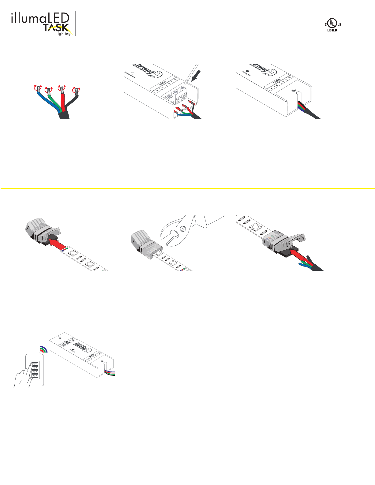
Wiring Receiver to RGB Tape Light Guide
Step 1: Connect Wire to Receiver
1. Strip 1-1/2" black sheathing from
RGB 4-wire Connection Wire. Strip 1/4"
insulation from each of the 4 colored
wires. Twist each wire and fold in half.
Step 2: Connect Wire to RGB Tape Light
1. Peel back 1/2" of adhesive protector
from back of RGB Tape Light; insert end
of Tape Light all the way into short side of
connector.
2. Loosen the 4 terminal screws on
OUTPUT side of Receiver. Insert the 4
connector wires into their corresponding
terminals, Blue to B, Green to G, Red to R,
Black to (V+). Tighten screws.
2. Close cap and press gently with pliers
to secure connection.
3. Replace Receiver terminal covers,
making sure wires are not pinched
3. Leaving insulation intact, insert the
4 colored RGB wires into corresponding
wire channel on long side of connector.
Close cap and press gently with pliers to
secure connection. The connector will cut
through insulation to make contact.
4. Turn on 120V AC to Power Supply and
pair Receiver to Controller.
38
Customer Service: 800.445.6404 • Design Services/Technical Support: 866.848.9094 • TaskLighting.com
Page 5
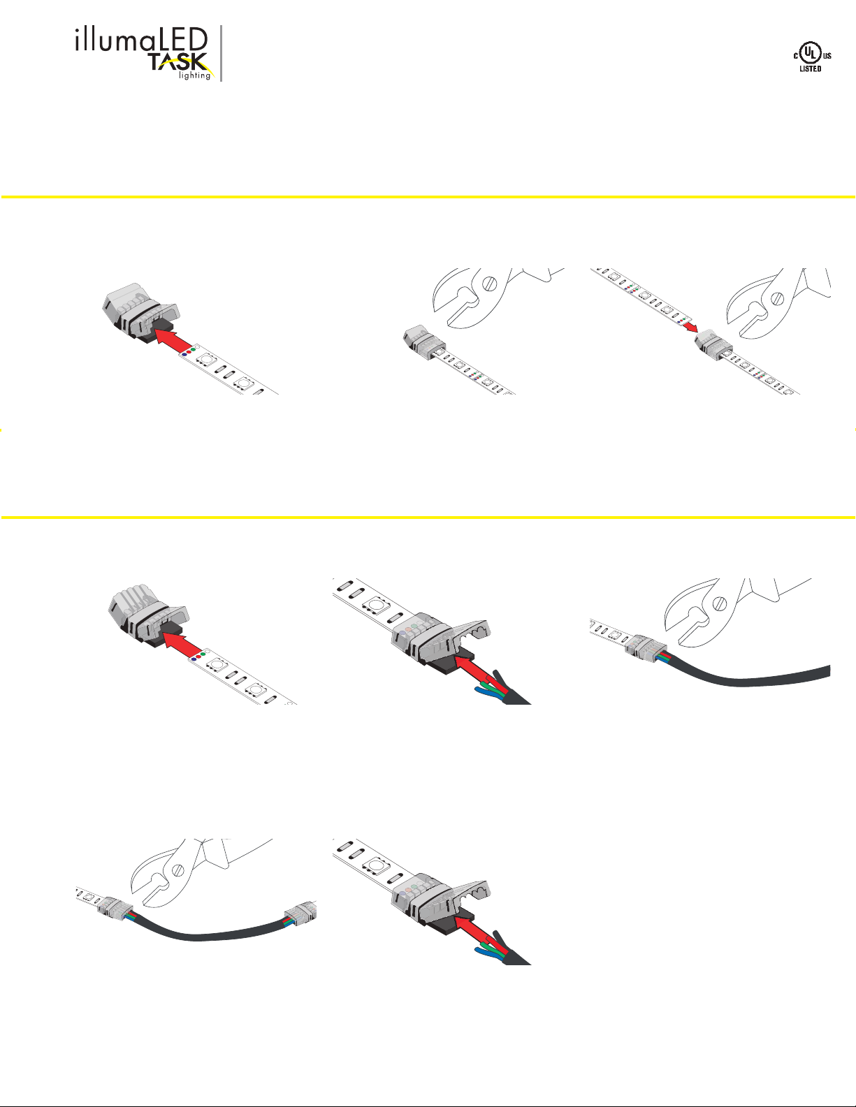
RGB Tape Light Connectors
Using Connectors to join cut lengths of RGB Tape Light
NOTE
Always cut RGB Tape Light with scissors at cut marks (located where black lines run through 4 solder points, found at 2” intervals)
OPTION 1: Using L-10MM-RGB-SC Tape to Tape Splice Connectors
1. Peel back 1/2” of RGB Tape Light
adhesive backing; insert end of RGB Tape
Light section all the way into one side of
connector.
2. Close cap and press gently with pliers
to secure connection.
3. Repeat with second RGB Tape
Light section and other side of
L-10MM-RGB-SC Connector.
OPTION 2: Using L-10MM-RGB-WSC Tape to 4-Conductor Wire Connectors
1. Peel back 1/2" of adhesive protector
from back of RGB Tape Light; insert end
of Tape Light all the way into short side
of connector. Close cap and press gently
with pliers to secure connection.
2. Leaving insulation intact, insert the
4 colored RGB wires into corresponding
wire channel on long side of connector.
Close cap and press gently with pliers to
secure connection. The connector will cut
through insulation to make contact.
3. Close cap and press gently with pliers
to secure connection.
4. Repeat with the other end of wire and a
second L-10MM-RGB-WSC Connector.
Customer Service: 800.445.6404 • Design Services/Technical Support: 866.848.9094 • TaskLighting.com
5. Peel back 1/2” of adhesive protector
from back of RGB Tape Light; insert end
of second Tape Light all the way into
short side of second connector. Close
cap and press gently with pliers to secure
connection.
39
Page 6

Pairing Instructions
Step 2: Pairing Receiver to Controller
1. Remove Controller from back plate,
slide battery compartment open, remove
battery, and discard clear plastic tab.
Reinsert battery, replace cover.
Step 2: Setting the Controller buttons
1. Press the COLOR button on the
Wireless Controller to rotate through the
colors, one by one. Alternatively, press
and hold the COLOR button to scroll
through colors. Release button when
desired color is reached.
2. Clear the receiver by pressing and
holding the Learning button until the lights
blink twice
2. To save a color, press and hold the M1
button until the lights ash. Continue the
same procedure with M2, M3, and M4
buttons.
3. Quickly press and release the
Learning button and, within 5 seconds,
press and release one of the 4-Zone
buttons on the Controller. When lights
blink once, Controller and Receiver are
paired.
3. Press the (| ) PLAY button to set a fade
mode. Press again to pause.
4. Press the BRIGHTNESS button ( ) and
hold to dim or brighten the lights.
40
Customer Service: 800.445.6404 • Design Services/Technical Support: 866.848.9094 • TaskLighting.com
 Loading...