

Page 1

Edition: V1.00/2010
Technical Manual
Page 2

GTS Technical Manual
technical manual swingo 1255 B Power V1.00 2010.03IVZ.fm
19. April 2010 Edition: V1.00/2010
Copyright © 2010, Diversey Inc.
Index
1 Foreword
1.1 Target 2
1.2 Technical Training 2
1.3 Technical Manual 2
1.4 Conclusion 3
2 Elementary
2.1 Health & Safety 2
2.2 ESD 2
3 General
3.1 General information 2
3.1.1 Part reference 2
3.1.2 Consumable supplies 2
3.1.3 Direction description 2
3.1.4 Power source 2
3.2 Required material 3
3.2.1 Tools 3
3.2.2 Material 3
4 Technical data
4.1 Machine range 2
4.2 Technical Information 3
4.2.1 Machine profile 3
4.2.2 Technical data 3
4.2.3 Machine speed 4
4.2.4 Dimensions and weights 4
4.2.5 Battery 6
4.2.6.1 Battery compartment 6
4.2.7.2 Battery specifications 6
4.2.8 Charger 7
4.2.9 Brush system 7
4.2.10 Suction power 8
4.2.11 Additional 8
4.3 Accessories & Additional parts 9
4.3.1 Accessories 9
4.3.2 Additional parts 9
5Mechanical
5.1 Mechanical sequences 2
5.1.1 Handle/Upper part 2
5.1.2.1 Replacing of microswitch 2
5.1.3.2 Replacing of hall sensor board 3
5.1.4.3 Replacing of throttle lever 5
5.1.5.4 Replacing of vacuum motor 6
5.1.6.5 Replacing of tank cover 8
5.1.7 Squeegee lowering mechanism 11
5.1.8.1 Replacing of squeegee bracket spring 11
5.1.9.2 Replacing of swinging arm long 12
Page 3

GTS Technical Manual
technical manual swingo 1255 B Power V1.00 2010.03IVZ.fm
19. April 2010 Edition: V1.00/2010
Copyright © 2010, Diversey Inc.
5.1.10 Squeegee 13
5.1.11.1 Replacing of fixation spring 13
5.1.12.2 Replacing of front blade 14
5.1.13.3 Replacing of back blade 15
5.1.14 Lower part & tank 16
5.1.15.1 Replacing of tank 16
5.1.16.2 Replacing of castor wheel 18
5.1.17.3 Replacing of filter 24V 19
5.1.18.4 Replacing of pump 20
5.1.19 Drive, Wheel group 22
5.1.20.1 Replacing of traction unit 22
5.1.21 Tool lowering unit 24
5.1.22.1 Replacing of foot lever 24
5.1.23.2 Replacing of pusher rack 26
5.1.24.3 Replacing of electrical brush unit (EBU) 27
5.1.25 Brush drive unit 28
5.1.26.1 Replacing of brush drive unit 28
5.1.27 Brush drive 30
5.1.28.1 Replacing of brush belt 30
5.1.29.2 Replacing of brush pulley 33
5.1.30.3 Replacing of motor & motor belt 35
5.1.31.4 Replacing of intermediate pulley 37
6Electrical
6.1 System architecture 2
6.1.1 General 2
6.1.2 System overview 2
6.1.3 Emergency loop 3
6.2 Electrical sequences 4
6.2.1 Dashboard 4
6.2.2.1 Replacing of dashboard 4
6.2.3.2 Connections 5
6.2.4 Dashboard service menu 9
6.2.5.1 Reset service LED 9
6.2.6 Power electronics 10
6.2.7.1 Replacing of power electronics 10
6.2.8.2 Connections 11
6.2.9 Charger 15
6.2.10.1 Replacing of charger 15
6.2.11.2 Connectors 15
6.3 Schematics/System 18
6.3.1 Battery connection 18
6.3.2 Electrical schematic 19
7 Additional information
7.1 Available GTS Newsletter/Instructions 2
8 Revision
9Appendix
10 Notes
Page 4

19. April 2010 Edition: V1.00/2010
Copyright © 2010, Diversey Inc.
Technical Manual
1 Foreword
Page 5

GTS Technical Manual
19. April 2010 Edition: V1.00/2010 1-2
Copyright © 2010, Diversey Inc.
01.0 swingo 1255 - foreword.fm
1 Foreword
1.1 Target
To serve our customers faster and more efficient it is important to achieve a general
standard of technical know how with our partners in the market.
Therefore we developed a new Technical Training concept which is based on e-spares.
The concept consists of a Technical Training and a Technical Manual.
These two tools will be produced for each newly launched machine with a certain complexity. The Technical Manual will be available as PDF file and can be downloaded from
e-spares. The Technical Training documentation will be distributed after having attended a the technical training.
1.2 Technical Training
The Technical Training is addressed as reference book for the technical training sessions and will be distributed to the floor care responsible and/or to the technical training responsible after attending a training session provided by GTS (max. 2 persons
per country).
The intension is, that after this session, a technical trainer is able to perform technical
training for their local technical staff and in this way to transfer the knowledge to all
service technicians.
The Technical Training is not intended as manual for the service technicians and will
be distributed only to the training responsible of each country.
1.3 Technical Manual
The Technical Manual is addressed to the service technicians and should be translated
and distributed after a technical training.
It contains a summary of procedures, hints and suggestions etc. which are helpful and
Page 6

GTS Technical Manual
19. April 2010 Edition: V1.00/2010 1-3
Copyright © 2010, Diversey Inc.
01.0 swingo 1255 - foreword.fm
essential for the daily business. The Technical Manual can be downloaded from espares/documents.
1.4 Conclusion
We are convinced that the new Technical Training concept together with the Technical
Manual are powerful tools, which will help our service organisations to achieve a higher level of quality in repairs and customer satisfaction.
If you have any comments or questions do not hesitate to contact your country responsible.
Sincerely yours
GTS Team
Page 7

19. April 2010 Edition: V1.00/2010
Copyright © 2010, Diversey Inc.
Technical Manual
2 Elementary
Page 8

GTS Technical Manual
19. April 2010 Edition: V1.00/2010 2-2
Copyright © 2010, Diversey Inc.
02.0 swingo 1255 - elementary.fm
2Elementary
2.1 Health & Safety
Scrubber dryers may be powered by mains electricity or batteries. There are risks associated with both, which call for proper precautions, such as the provision of good
ventilation and the elimination of risk of ignition.
All work, implemented on such machines, should only be performed by trained personnel in accordance with local regulations.
Before working on such a machine, isolate it from any electrical source.
Always wear the required personal protective equipment (including gloves and goggles that must be worn when potentially exposed to any hazardous material and when
carrying out hazardous work tasks).
Note that parts may be contaminated with chemical product. If possible flush hoses
out with fresh water prior to carrying out any maintenance. For information on chemical products that are used in this machine, please carefully read the product label
and Material Safety Data Sheet (MSDS).
Empty water tanks prior to carrying out any maintenance. Ensure contaminated water
is emptied into an approved drain. Avoid pollution.
2.2 ESD
Static electricity is electricity at rest or the accumulation of electric charge, as opposed to an electric current which is the movement of electricity. The flow or movement of people and/or materials in and through the environment causes separation
and therefore static electricity. A familiar example of static electricity is when a person walks across a carpeted floor. Static electricity/electrostatic charge is generated
simply by the contact and separation of the soles of that individual's shoes from the
carpeted floor.
Electrostatic Discharge (ESD) occurs when the electrostatic charge is transferred from
a material that carries the charge to an electrostatic sensitive device. In the example
above, this electrostatic discharge is the „shock“ felt after walking across the carpeted
Page 9

GTS Technical Manual
19. April 2010 Edition: V1.00/2010 2-3
Copyright © 2010, Diversey Inc.
02.0 swingo 1255 - elementary.fm
floor and then touching a door knob. It is this electrostatic discharge, which comes in
varying degrees, that can be most damaging to electrical devices and other industrial,
commercial and consumer products.
Static electricity, a natural phenomenon and consequently electrostatic discharge are
the primary causes of countless problems affecting industry, business and personal
life. These problems can be as simple as the shock resulting from walking across a
carpet; as costly as the destruction of sensitive electronic components or jamming of
machinery.
Almost any material can generate static electricity. The ability to store or unload the
charge depends on the type of material.
Static can damage devices, which can result in immediate product failure to operate.
In contrast, static damage can go undetected for a period of time and the results are
product failure once the product is in service.
Electrostatic fields are associated with charged objects.
The degree of severity of ESD events is contingent upon the type of discharge which
occurs. The three most common ESD charge transfers are:
• from an external object to the device
• from a device to another object
• resulting from electrostatic fields
Please do not store electronics without ESD bags at any time.
Page 10

19. April 2010 Edition: V1.00/2010
Copyright © 2010, Diversey Inc.
Technical Manual
3 General
Page 11

GTS Technical Manual
19. April 2010 Edition: V1.00/2010 3-2
Copyright © 2010, Diversey Inc.
02.5 swingo 1255 - general.fm
3 General
3.1 General information
3.1.1 Part reference
Explicitly mentioned parts are defined by references corresponding
to the e-spares spare parts list.
E.g. Tank axle (02/118) corresponds to the parts list on e-spares,
sub assembly 2, position 118.
3.1.2 Consumable supplies
If you have to remove cable ties then position the new ones at the
original place.
If you have to remove self locking nuts, you should replace them
by new ones.
3.1.3 Direction description
On the „RH“ always means on the right hand side of the machine in
working direction (when you are standing behind the machine).
On the „LH“ always means on the left hand side of the machine in
working direction (when you are standing behind the machine).
3.1.4 Power source
Depending on the work it might be required to remove the power
source (mains/batteries) from the machine.
The in here mentioned sequences (mechanical and electrical) are
based on the assumption that the power source (mains/batteries)
were removed from the machine before.
Page 12

GTS Technical Manual
19. April 2010 Edition: V1.00/2010 3-3
Copyright © 2010, Diversey Inc.
02.5 swingo 1255 - general.fm
3.2 Required material
3.2.1 Tools
• A standard range of tools is required e.g.
• Fork spanners
• Allen keys
• Torx keys
3.2.2 Material
• No special tools are required.
The above listings are only a recommendation for the technical
training.
Page 13

19. April 2010 Edition: V1.00/2010
Copyright © 2010, Diversey Inc.
Technical Manual
4 Technical data
Page 14

GTS Technical Manual
19. April 2010 Edition: V1.00/2010 4-2
Copyright © 2010, Diversey Inc.
04.0 swingo 1255 B Power - technical data.fm
4Technical Data
4.1 Machine range
SKU Description Version Series
7516829 TASKI swingo 1255
B Power
01
7516830 TASKI swingo 1255
B Power
BMS SEV 01
7516831 TASKI swingo 1255
B Power
BMS EURO 01
7517575 TASKI swingo 1255
B Power
BMS DK 01
7517715 TASKI swingo 1255
B Power
BMS NA 01
7516833 TASKI swingo 1255
B Power
BMS UK 01
7516832 TASKI swingo 1255
B Power
BMS EBU SEV 01
7516834 TASKI swingo 1255
B Power
BMS EBU EURO 01
7517576 TASKI swingo 1255
B Power
BMS EBU DK 01
7516836 TASKI swingo 1255
B Power
EBU 01
Table 1: Machine range
Page 15

GTS Technical Manual
19. April 2010 Edition: V1.00/2010 4-3
Copyright © 2010, Diversey Inc.
04.0 swingo 1255 B Power - technical data.fm
4.2 Technical Information
4.2.1 Machine profile
4.2.2 Technical data
Pos. Value
Theoretical performance (at 4.5 km/h) (m²/h) 2475
Practical performance (m²/h) 1250
Working width (mm) 550
Squeegee width (mm) 800
Solution tank (l) 55
Recovery tank (l) 55
Table 2: Machine profile
Pos. Value
Noise level (ECO mode) dB(A) <60
Vibration (m/s2) < 0.5
Approvals ÖVE
Nominal consumption (W) 1000
Power drive motor (W) 200
Power suction motor (W) 490
Voltage (V) 24
Battery capacity max. (maintenance-free/wet) (Ah)/C5 50/70
Battery autonomy max.
(70 Ah maintenance free battery)
(h) up to 3.0
Internal charger only in BMS
Protection grade machine IPX3
Protection class charger (BMS model) I
Protection class charger (BMS model DK) II
Table 3: Technical Data
Page 16

GTS Technical Manual
19. April 2010 Edition: V1.00/2010 4-4
Copyright © 2010, Diversey Inc.
04.0 swingo 1255 B Power - technical data.fm
4.2.3 Machine speed
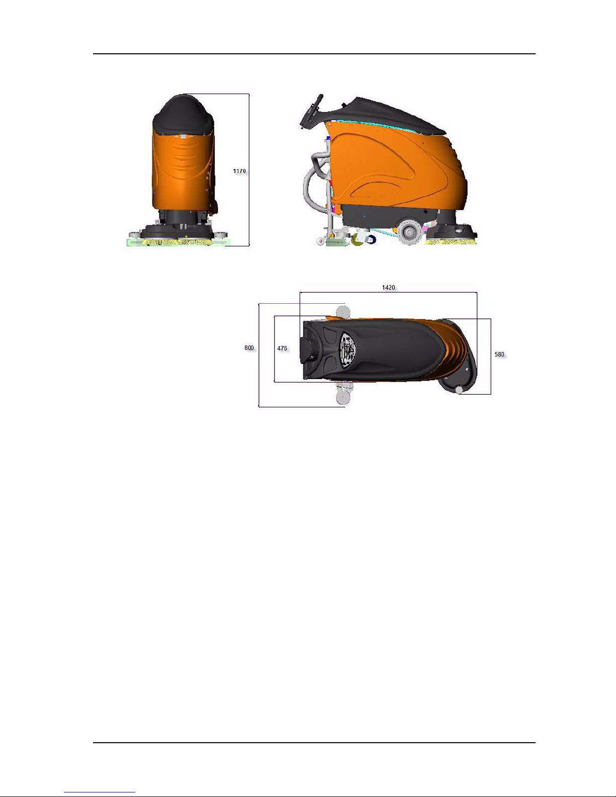
4.2.4 Dimensions and weights
Pos. Value
Transportation speed (km/h) 4.5
Cleaning speed (km/h) 4.5
Ramp max. (%) 2
Table 4: Machine speed
Pos. Value
Dimensions L/W/H (mm) 1420/580/1170
Door pass through with squeegee (mm) 800
Battery compartment L/W/H (mm) 700 x 340 x 240
Net weight without batteries; empty tank (kg) 81
Weight, ready to use (kg) 260
Max. floor pressure (N/mm2) 0.39
Wheel diameter front (mm) 200
Wheel diameter - castor (mm) 100
Table 5: Dimensions and weights
Page 17
GTS Technical Manual
19. April 2010 Edition: V1.00/2010 4-5
Copyright © 2010, Diversey Inc.
04.0 swingo 1255 B Power - technical data.fm
Picture 1: Dimensions
Page 18
GTS Technical Manual
19. April 2010 Edition: V1.00/2010 4-6
Copyright © 2010, Diversey Inc.
04.0 swingo 1255 B Power - technical data.fm
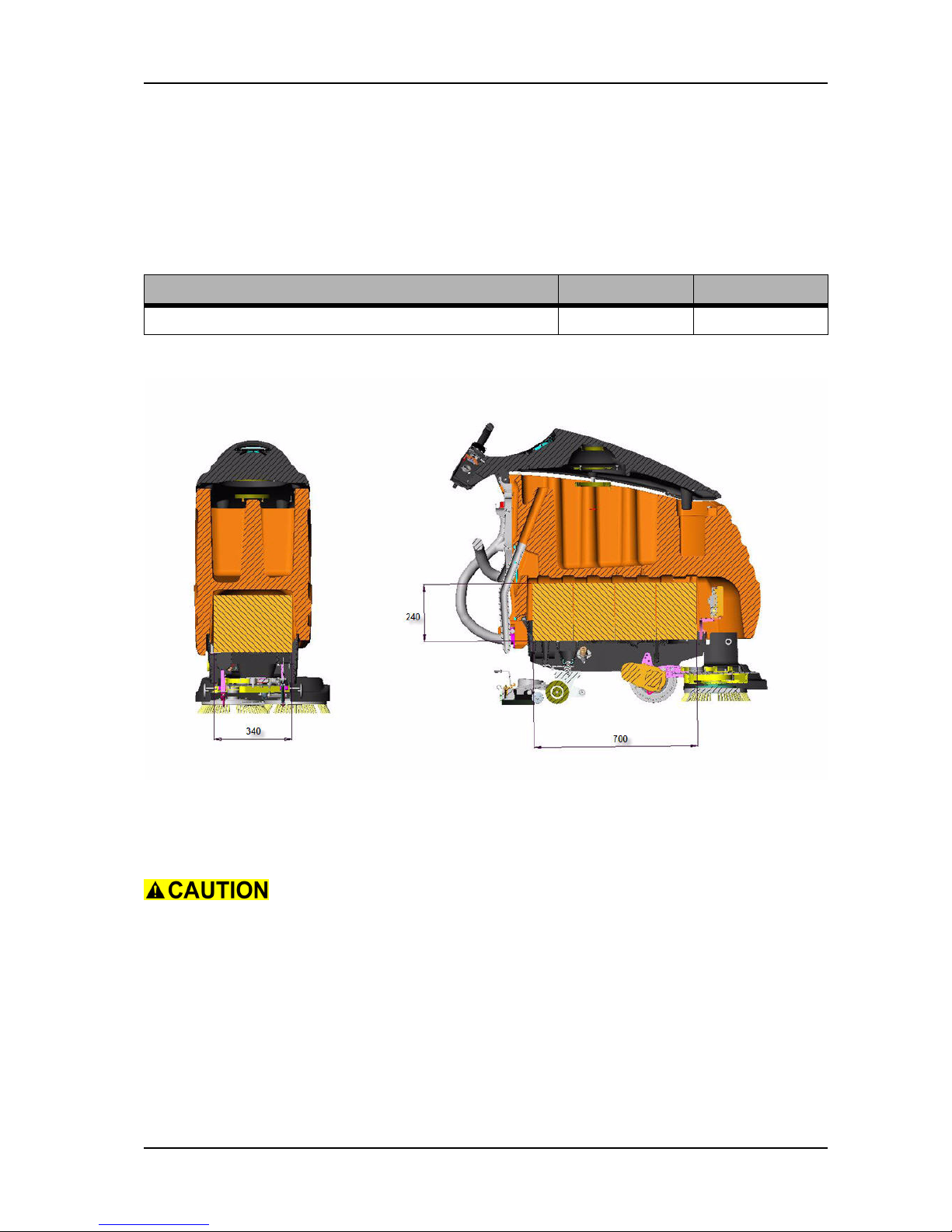
4.2.5 Battery
4.2.5.1 Battery compartment
Picture 2: Battery compartment
4.2.5.2 Battery specifications
Please use batteries from Excide/Sonnenschein, as this is our
preferred partner.
BMS is only for dry (gel) batteries.
For the correct connection of the batteries, pay attention to the
voltage of each battery and the correct connection. Therefore refer
to e-spares.
Pos. Value
Battery compartment L/W/H (mm) 700 x 340 x 240
Table 6: Battery compartment
Page 19

GTS Technical Manual
19. April 2010 Edition: V1.00/2010 4-7
Copyright © 2010, Diversey Inc.
04.0 swingo 1255 B Power - technical data.fm
4.2.6 Charger
4.2.7 Brush system
Supplier Type
VoltageAhLength [mm]
Width [mm]
Height [mm]
Weight [kg]
Excide Sonnenschein GF12050 12 50 278 175 190 20
Excide Sonnenschein GF12070 12 70 330 171 236 28
Table 7: Dry (gel) batteries
Pos. Value
Primary V 100 - 240
Primary Hz 50 - 60
Secondary V 24
Secondary A 20
Secondary (DK model) A 25
Protection class charger (BMS model) I
Protection class charger (BMS model DK) II
Approval CE
Cable length / BMS cable (m) 3
Table 8: Charger
Pos. Value
Brush system (mm) 2 x 280
Brush motor (W) 750
Brush speed (rpm) 195
Brush pressure max. (kg) 48
Table 9: Brush system
Page 20

GTS Technical Manual
19. April 2010 Edition: V1.00/2010 4-8
Copyright © 2010, Diversey Inc.
04.0 swingo 1255 B Power - technical data.fm
4.2.8 Suction power
4.2.9 Additional
Pos. Value
Vacuum motor (W) 490
Max. air flow (l/s) 32
Max. vacuum (mbar) 118
Max. vacuum (kPa) 11.8
Table 10: Suction power
Pos. Value
Cleaning Solution Dosing CSD system
Brush lifting mechanical or
electrical (EBU)
Squeegee lifting mechanical
Table 11: Additional
Page 21

GTS Technical Manual
19. April 2010 Edition: V1.00/2010 4-9
Copyright © 2010, Diversey Inc.
04.0 swingo 1255 B Power - technical data.fm
4.3 Accessories & Additional parts
4.3.1 Accessories
4.3.2 Additional parts
SKU Article
7510634 Pad drive harpoon grip 280 mm
7510631 Scrubbing brush standard 280 mm
7510632 Scrubbing brush washed concrete 280 mm
7510633 Scrubbing brush abrasive 280 mm
4122535 Blade front
4122536 Blade back
Table 12: Accessories
SKU Article
4127204 Blades front Type 816 (Closed front blade)
4127052 Double back blades (56/2.5 x 858)
4075260 External hour counter for battery models
4122526 PU traction wheel (brown)
4123154 PU wheels soft
4122527 Castor wheel brown 100
Table 13: Additional parts
Page 22

19. April 2010 Edition: V1.00/2010
Copyright © 2010, Diversey Inc.
Technical Manual
5 Mechanical
Page 23

GTS Technical Manual
19. April 2010 Edition: V1.00/2010 5-2
Copyright © 2010, Diversey Inc.
05.0 swingo 1255 B Power - mechanics.fm
5 Mechanical
5.1 Mechanical sequences
5.1.1 Handle/Upper part
5.1.1.1 Replacing of microswitch
Picture 1: Microswitch
Remove
• Remove the 3 screws of the cover.
• Remove the cover.
• Unplug hour counter wires from the hour counter or the cover.
• Remove spring of the microswitch.
• Remove microswitch from fixation.
• Disconnect wires from microswitch.
Mount
• Connect new microswitch to the wires.
• Position the microswitch on the fixation.
Ensure that the microswitch is positioned correctly on the fixation
(pins).
• Assemble microswitch spring.
• Test if the microswitch is functional when moving the throttle
levers.
• Connect the hour counter wires to the hour counter or to the
cover.
• Assemble the cover.
• Tighten the cover with the 3 screws.
Page 24
GTS Technical Manual
19. April 2010 Edition: V1.00/2010 5-3
Copyright © 2010, Diversey Inc.
05.0 swingo 1255 B Power - mechanics.fm
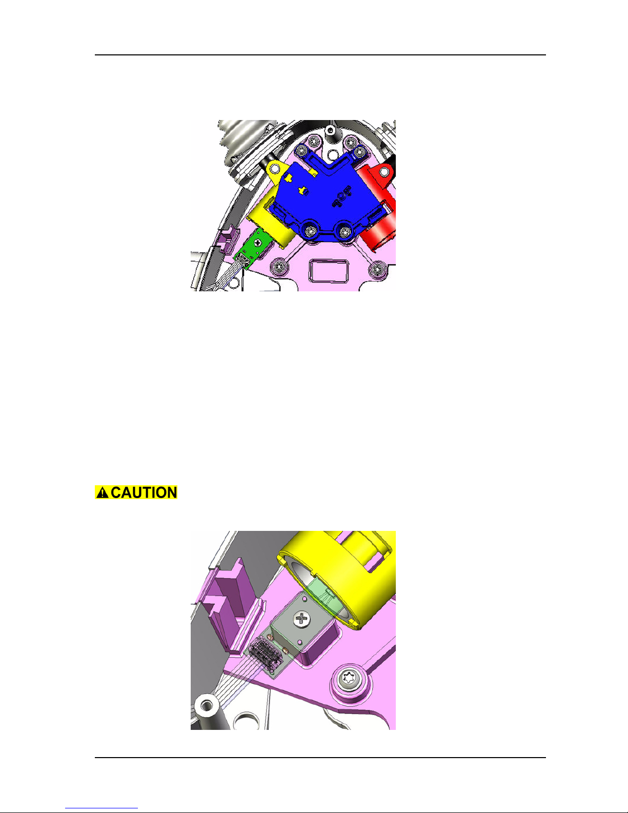
5.1.1.2 Replacing of hall sensor board
Picture 2: Throttle hall sensor
Remove
• Remove microswitch according to chapter REPLACING OF
MICROSWITCH.
• Remove the 5 screws of the dashboard.
• Remove dashboard.
• Disconnect hall sensor compl. ribbon cable from dashboard.
• Thread out hall sensor compl. ribbon cable.
• Unscrew mechanic hall sensor compl. fixation.
• Remove mechanic hall sensor compl.
Mount
• Build in mechanic hall sensor compl.
Make sure that the mechanic hall sensor compl. is placed correctly
on the pins of the support before tightening the screw.
Page 25

GTS Technical Manual
19. April 2010 Edition: V1.00/2010 5-4
Copyright © 2010, Diversey Inc.
05.0 swingo 1255 B Power - mechanics.fm
Picture 3: Hall sensor positioning
• Place and tighten screw of mechanic hall sensor compl.
• Thread in the hall sensor compl. ribbon cable.
• Connect hall sensor compl. ribbon cable to the dashboard.
• Position dashboard and fix it with the 5 screws.
• Complete assembling according to the chapter REPLACING OF
MICROSWITCH.
Page 26
GTS Technical Manual
19. April 2010 Edition: V1.00/2010 5-5
Copyright © 2010, Diversey Inc.
05.0 swingo 1255 B Power - mechanics.fm
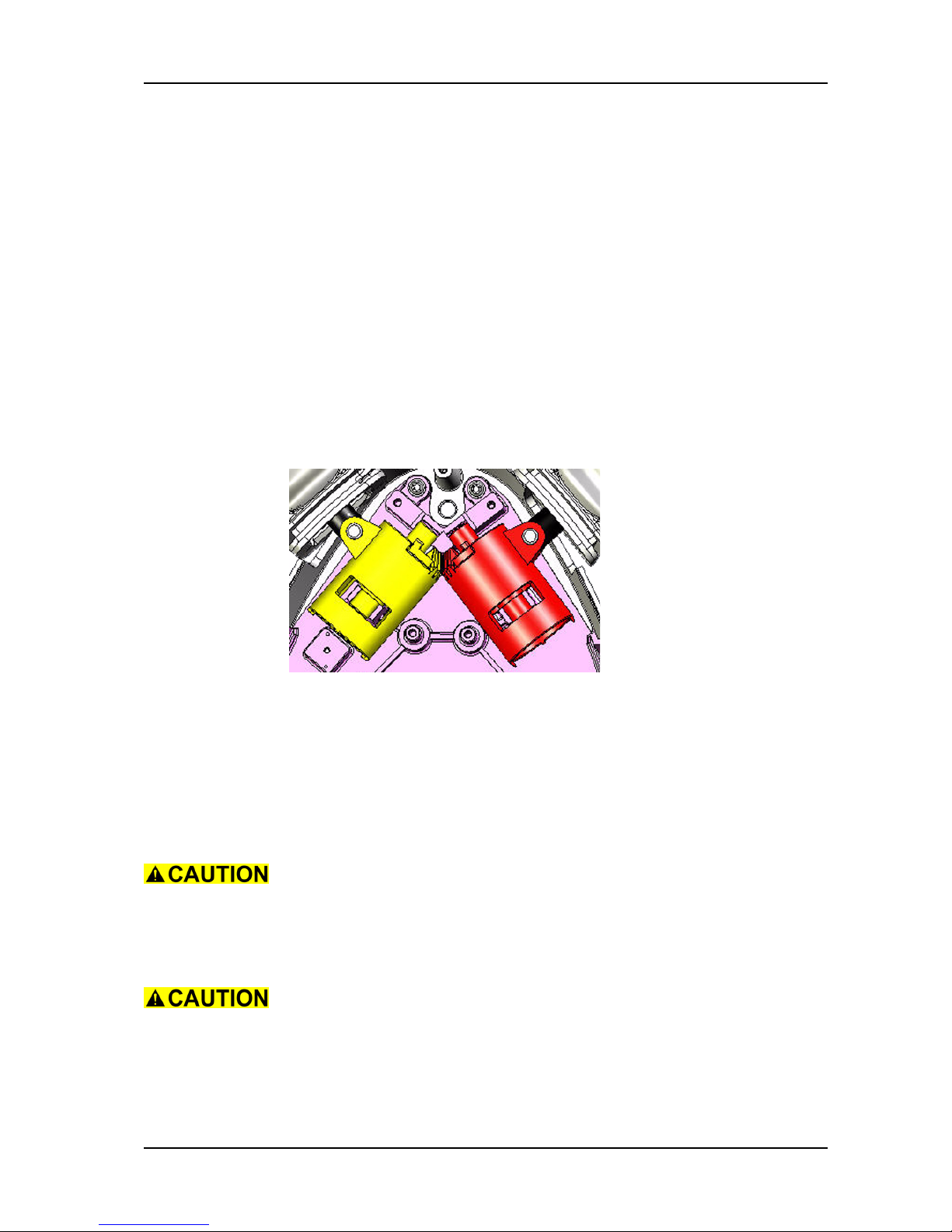
5.1.1.3 Replacing of throttle lever
Remove
• Remove microswitch according to chapter REPLACING OF
MICROSWITCH.
• Unscrew mechanic hall sensor compl. fixation.
• Remove mechanic hall sensor compl.
• Unscrew the four screws of the switch holder bracket.
• Remove switch holder bracket.
• Put the locking lever to the left.
• Remove both throttle levers.
Remarks
The lever parts can be replaced as single pieces according to espares.
Picture 4: Throttle levers position
Pay attention that the solenoid is placed on the left side (hall sensor
side).
Make sure that the rubber covers are placed in the slots.
Mount
• Assemble both throttle levers.
Ensure that the lever toothed wheels are positioned in the center of
the possible movement.
• Mount switch holder bracket.
• Build in mechanic hall sensor compl.
Make sure that the mechanic hall sensor compl. is placed correctly
on the pins of the support before tightening the screw.
• Place and tighten the screw of mechanic hall sensor compl.
• Complete assembling according to the chapter REPLACING OF
MICROSWITCH.
Page 27

GTS Technical Manual
19. April 2010 Edition: V1.00/2010 5-6
Copyright © 2010, Diversey Inc.
05.0 swingo 1255 B Power - mechanics.fm
5.1.1.4 Replacing of vacuum motor
Picture 5: Vacuum motor
Remove
• Open the tank cover.
• Loosen the screw on the tank cover on the support side (RH).
• Loosen the screw on the other side (LH).
• Close the tank cover.
• Open the tank cover without base plate.
Picture 6: Base plate
• Disconnect vacuum motor wires from connection block.
• Remove sealing of vacuum motor to tank cover.
• Remove capacitor from motor.
• Unscrew the 3 screws of the vacuum motor protection plate.
• Remove the vacuum motor protection plate.
• Remove vacuum motor fixation sealings.
• Remove the vacuum motor.
• Remove bottom sealing of the vacuum motor.
Mount
• Position bottom sealing of the vacuum motor.
• Build in the vacuum motor.
• Position vacuum motor fixation sealings.
• Assemble vacuum motor protection plate.
Page 28

GTS Technical Manual
19. April 2010 Edition: V1.00/2010 5-7
Copyright © 2010, Diversey Inc.
05.0 swingo 1255 B Power - mechanics.fm
Remarks
Ensure that the vacuum motor sealings are properly positioned
before assembling the protection plate.
• Position and tighten the vacuum motor protection plate
fixation.
Remarks
Ensure that the turn protection is placed (spin protection).
• Mount capacitor to the vacuum motor and connect wires.
• Position top sealing of vacuum motor.
• Connect vacuum motor wires to connection block.
• Close tank cover and position it on the base plate.
• Open tank cover together with base plate.
• Use the tank cover support.
• Tighten base plate fixation on the LH side.
• Tighten base plate fixation on the tank support side (RH).
Tighten the fixation rubbers smoothly.
Remarks
Check at the end if the vacuum motor top sealing is positioned
properly. If necessary, unscrew and remove the dashboard and
check.
Page 29

GTS Technical Manual
19. April 2010 Edition: V1.00/2010 5-8
Copyright © 2010, Diversey Inc.
05.0 swingo 1255 B Power - mechanics.fm
5.1.1.5 Replacing of tank cover
Picture 7: Tank cover
Remove
• Unscrew dashboard fixation.
• Remove dashboard and disconnect all cables.
• Remove the 3 screws of handle cover.
• Remove handle cover.
• Unplug hour counter wires from the hour counter or the cover.
• Remove screws (01/103) of throttle lever bracket.
• Thread out hall sensor ribbon cable and remove the complete
throttle lever system.
• Unscrew handle fixation to the tank cover (01/106 and 01/
107).
• Remove handle from tank cover.
• Unscrew and remove rear panel (09/103).
• Open the tank cover.
• Loosen the screw (01/107) on the tank cover on the support
side (RH).
• Loosen the screw on the other side (LH).
• Close the tank cover.
• Open the tank cover without base plate.
Picture 8: Base plate
• Disconnect vacuum motor cable at connection block (cable to
Page 30

GTS Technical Manual
19. April 2010 Edition: V1.00/2010 5-9
Copyright © 2010, Diversey Inc.
05.0 swingo 1255 B Power - mechanics.fm
power electronics).
• Remove cable fixation from base plate.
• Thread out cables from tank cover.
•Close tank cover.
• Remove fixation screw (09/123) of axle on one side.
• Push out axle (09/121).
• Remove complete cover.
• According to what you need to exchange, remove the existing
parts from the tank cover and place it on the new one.
Mount (Drilling of hole for tank cover axle)
Assemble the tank cover lock at the end of this sequence.
• Position the base plate on the new tank cover.
• Fix the base plate on the tank cover.
• Position the tank cover including base plate correctly on the
tank.
Make sure that the sealings are nicely positioned.
• Drill the hole for the tank axle without pressing the tank cover
down onto the tank (drill with 10 mm).
• Mount the tank cover axle.
• Fix the axle with the screws.
Remarks
Ensure that the protection shield (01/108) is positioned between
the tank and the base plate.
• Open tank cover.
• Thread in cable into the tank cover.
Remarks
Ensure that the cables are positioned that way, that they can not
be squeezed by the tank cover.
• Fix cable on the base plate.
• Connect vacuum motor to the connection block (cable from
power electronics).
• Close tank cover and position it on the base plate.
• Open tank cover together with base plate.
• Use the tank cover support.
• Tighten base plate fixation on the LH side.
• Tighten base plate fixation on the tank support side (RH).
Page 31

GTS Technical Manual
19. April 2010 Edition: V1.00/2010 5-10
Copyright © 2010, Diversey Inc.
05.0 swingo 1255 B Power - mechanics.fm
Remarks
Check at the end if the vacuum motor top sealing is positioned
properly. If necessary, unscrew and remove the dashboard and
check.
• Open tank cover.
• Assemble tank cover lock.
Adjustment
Adjust the tank cover lock and ensure a proper opening and closing
of the tank cover.
• Mount the rear panel.
• Assemble handle on the tank cover with the 7 screws.
• Position the complete throttle lever system.
• Thread in the hall sensor cable to the dashboard.
• Fix the throttle lever bracket with the screws.
• Position wires on the external hour counter or on the handle
cover, depending on the setup.
• Mount the handle cover.
• Connect wires to dashboard.
• Assemble dashboard on the tank cover.
Page 32

GTS Technical Manual
19. April 2010 Edition: V1.00/2010 5-11
Copyright © 2010, Diversey Inc.
05.0 swingo 1255 B Power - mechanics.fm
5.1.2 Squeegee lowering mechanism
5.1.2.1 Replacing of squeegee bracket spring
Picture 9: Squeegee lowering
Remove
• Remove the squeegee from the fixation.
1 Remove one circlip of rear axle.
2 Press down the swinging arm (02/111) to release tension on
axle and remove it.
3 Put the swinging arm in transport position (all the way up to
the chassis).
4 Remove pressure spring by pulling it out.
Mount
• Put the swinging arm all the way up to the chassis.
• Mount the new pressure spring.
Remarks
Thread spring into the upper bolt (02/104) first and then push it all
the way in.
• Press down the swinging arm and assemble the rear axle.
Ensure that the slide bearings are properly positioned.
• Position the circlip on the rear axle.
Page 33

GTS Technical Manual
19. April 2010 Edition: V1.00/2010 5-12
Copyright © 2010, Diversey Inc.
05.0 swingo 1255 B Power - mechanics.fm
5.1.2.2 Replacing of swinging arm long
Picture 10: Swinging arm long
Remove
• Remove castor wheel according to chapter REPLACING OF
CASTOR WHEEL.
1 Loosen the fixation screw (02/107) with 8mm Allen key and
17mm fork spanner/nut.
• Remove complete swinging arm long.
Mount
• Assemble the complete swinging arm long.
• Tighten the fixation screw.
• Assemble the castor wheel according to chapter REPLACING
OF CASTER WHEEL.
Adjustment
Make sure that the reinforcement plate (04/103) is positioned
correctly, so the hexagon screw (04/102) for the castor wheel fits
nicely.
Tighten the screw with 60 Nm.
Service
Apply gear/bearing lubricant on the slide bearing (02/108).
Page 34

GTS Technical Manual
19. April 2010 Edition: V1.00/2010 5-13
Copyright © 2010, Diversey Inc.
05.0 swingo 1255 B Power - mechanics.fm
5.1.3 Squeegee
Picture 11: Squeegee
5.1.3.1 Replacing of fixation spring
Picture 12: Offset fixation
Remove
• Unscrew the 2 screws of the offset (03/113) fixation.
• Remove the offset and the spring (03/114).
• Remove the spring from the offset.
Mount
• Assemble the new spring on the offset.
• Assemble the offset and the spring on the squeegee.
• Mount the screws of the offset.
Page 35

GTS Technical Manual
19. April 2010 Edition: V1.00/2010 5-14
Copyright © 2010, Diversey Inc.
05.0 swingo 1255 B Power - mechanics.fm
5.1.3.2 Replacing of front blade
Remove
Picture 13: Front blade fixation
• Tighten fixation screw until the tightening strap can be
removed (the pressure to the outer sides of the squeegee
body will be reduced).
• Remove front blade.
Mount
• Position new front blade.
Picture 14: Tightening strap front blade
• Position tightening strap.
• Loosen fixation screw until the blade is proper fixed on the
squeegee body.
Ensure that the tightening strap is positioned correct (thin part to
the bottom).
If you over tighten the tightening strap it can bulge.
Page 36

GTS Technical Manual
19. April 2010 Edition: V1.00/2010 5-15
Copyright © 2010, Diversey Inc.
05.0 swingo 1255 B Power - mechanics.fm
5.1.3.3 Replacing of back blade
Picture 15: Back blade
Remove
• Loosen the fixation screws on both sides to release the
pressure.
• Remove the tightening strap.
• Remove the back blade.
Mount
• Position new back blade.
• Position tightening strap.
• Tighten fixation screws until the blade is proper fixed on the
squeegee body.
Remarks
Pay attention that the tightening strap is positioned in the center.
Ensure that the tightening strap is positioned correct (thin part to
the bottom).
If you over tighten the tightening strap it can bulge.
Page 37

GTS Technical Manual
19. April 2010 Edition: V1.00/2010 5-16
Copyright © 2010, Diversey Inc.
05.0 swingo 1255 B Power - mechanics.fm
5.1.4 Lower part & tank
5.1.4.1 Replacing of tank
Picture 16: Tank
Remove
• Remove tank cover according to chapter REPLACING OF TANK
COVER.
• Remove fresh water hose from valve body (08/107).
• Remove rear panel.
• Unscrew charger jack from rear panel (09/103).
• Unlock battery compartment by removing screws of locking
system.
• Open the battery compartment.
• Thread out wiring and hoses to the battery compartment.
• Close battery compartment.
Page 38

GTS Technical Manual
19. April 2010 Edition: V1.00/2010 5-17
Copyright © 2010, Diversey Inc.
05.0 swingo 1255 B Power - mechanics.fm
Picture 17: Water tank axle
• Remove water tank fixation screws (09/125).
• Remove water tank from axle.
• Remove the existing parts from the tank and place it on the
new one.
Mount
• Position the new water tank on the axle.
• Fix the water tank onto the axle with the two screws.
• Open the battery compartment.
• Thread in cables from the battery compartment.
• Close battery compartment.
• Assemble charger jack on the rear panel.
• Connect fresh water hose to the valve body (08/107).
• Assemble tank cover according to chapter REPLACING OF
TANK COVER.
• Adjust battery compartment lock.
• Lock the battery compartment on both sides with the screws
of the locking system.
Adjustment
Ensure that the screws of the lock can be properly positioned.
Page 39

GTS Technical Manual
19. April 2010 Edition: V1.00/2010 5-18
Copyright © 2010, Diversey Inc.
05.0 swingo 1255 B Power - mechanics.fm
5.1.4.2 Replacing of castor wheel
Picture 18: Castor wheel
Remove
• Unlock battery compartment on the LH side by removing the
screw of the locking system.
• Lay the machine on the LH side.
• Unlock battery compartment on the RH side by removing the
screw of the locking system.
• Open the battery compartment.
• Loosen the fixation screw (04/102) with a 19 mm fork
spanner/nut.
• Remove the complete castor wheel.
Mount
• Assemble castor wheel.
• Tighten the fixation screw with a 19 mm fork spanner/nut.
Adjustment
Tighten the screw with 70 Nm.
• Lock battery compartment on the RH side with the screw of
the locking system.
• Lift up the machine.
• Lock battery compartment on the LH side with the screw of the
locking system.
Page 40

GTS Technical Manual
19. April 2010 Edition: V1.00/2010 5-19
Copyright © 2010, Diversey Inc.
05.0 swingo 1255 B Power - mechanics.fm
5.1.4.3 Replacing of filter 24V
Picture 19: Filter 24V
Remove
• Remove filter cover of filter 24V.
Ensure that no water is in the fresh water system before you
disconnect the hoses or remove the filter cover.
• Remove fixation screws (08/124) from chassis.
• Thread out filter 24V from the chassis.
• Disconnect the fresh water connection.
• Disconnect the wires from coil.
• Remove complete filter 24V.
Mount
• Take new filter 24V.
• Connect wires to coil.
• Connect fresh water hoses to the filter 24V.
• Thread in the filter 24V on the chassis.
• Position fixation screws and tighten them.
• Position filter cover on the filter 24V.
Page 41

GTS Technical Manual
19. April 2010 Edition: V1.00/2010 5-20
Copyright © 2010, Diversey Inc.
05.0 swingo 1255 B Power - mechanics.fm
5.1.4.4 Replacing of pump
Picture 20: Pumps
Remove
• Unlock battery compartment by removing the screws of the
locking system.
• Open the battery compartment.
• Lower the brush drive unit to cleaning position without tools
underneath.
• Unscrew brush housing fixation screws.
• Remove the brush housing to get better access to the pump.
• Remove the screws (04/112) of the pump holder (04/122).
• Disconnect the pump wires.
• Loosen the hose clamps on both sides of the pump.
• Remove the fresh water hoses from the pump.
Picture 21: Pump
• Lift up pump holder and thread out pump from pump holder.
Mount
• Position new pump into pump holder.
Ensure that the pump is build in according to the water flow. The
arrow on the pump indicates the water flow direction.
Page 42

GTS Technical Manual
19. April 2010 Edition: V1.00/2010 5-21
Copyright © 2010, Diversey Inc.
05.0 swingo 1255 B Power - mechanics.fm
• Connect fresh water hoses to the pump.
• Tighten the hose clamps on both sides.
• Connect the pumps wires.
• Position and tighten the screw of the pump holder.
• Mount the brush housing.
• Position and tighten screws of brush housing.
• Close battery compartment.
• Lock battery compartment on both sides with the screws of
the locking system.
Page 43

GTS Technical Manual
19. April 2010 Edition: V1.00/2010 5-22
Copyright © 2010, Diversey Inc.
05.0 swingo 1255 B Power - mechanics.fm
5.1.5 Drive, Wheel group
5.1.5.1 Replacing of traction unit
Picture 22: Traction unit
Remove
• Unlock battery compartment by removing screws of locking
system.
• Open battery compartment.
• Disconnect traction unit wires from power electronics.
• Thread out wires from battery compartment.
• Close battery compartment.
• Lay machine to the LH side.
Remarks
For an EBU machine the next two steps are not necessary.
• Remove retaining ring (06/120) on one side.
• Remove axle (06/119).
• Remove the screws (05/106, EBU 05/111) for the brackets.
• Remove the fixation brackets (05/105).
• Remove traction unit including traction wheels.
Mount
• Position new traction unit including traction wheels.
• Position and tighten fixation brackets.
Page 44

GTS Technical Manual
19. April 2010 Edition: V1.00/2010 5-23
Copyright © 2010, Diversey Inc.
05.0 swingo 1255 B Power - mechanics.fm
Remarks
For an EBU machine the next two steps are not necessary.
• Position the axle.
• Mount the retaining ring.
• Lift up the machine again.
• Open battery compartment.
• Thread in wires of traction unit into the battery compartment.
• Connect traction unit wires to power electronics.
• Look the battery compartment on both sides with the screws
of the locking system.
Adjustment
Make sure that the pusher rack (06/106) is adjusted to the distance
of 381mm.
Picture 23: Pusher rack
Page 45

GTS Technical Manual
19. April 2010 Edition: V1.00/2010 5-24
Copyright © 2010, Diversey Inc.
05.0 swingo 1255 B Power - mechanics.fm
5.1.6 Tool lowering unit
Picture 24: Tool lowering unit
5.1.6.1 Replacing of foot lever
Picture 25: Foot lever
Remove
• Remove the pedal pad (06/101) from the foot lever (06/102).
• Lay the machine on the LH side.
• Unplug the microswitch.
• Remove the screw (06/117) for microswitch fixation.
• Remove the microswitch (06/118).
• Remove the retaining ring (06/120) on one side.
• Remove the axle (06/119) from the pusher rack (06/106).
• Pull out the stop pin (06/108).
• Remove the bolt (06/107) for the foot lever fixation.
Page 46

GTS Technical Manual
19. April 2010 Edition: V1.00/2010 5-25
Copyright © 2010, Diversey Inc.
05.0 swingo 1255 B Power - mechanics.fm
Remarks
To pull out the bolt, you need to thread in a screw into the bolt.
Dimensions: M6, min. length 30mm.
• Remove the foot lever (06/102)
Mount
• Build in new foot lever.
• Position the bolt for the foot lever fixation.
• Insert the stop pin.
• Position the axle into the pusher rack.
• Mount the retaining ring.
• Position the microswitch.
• Mount screw for microswitch and adjust accordingly.
Adjustment
The foot lever switch has to switch when the foot lever passes the
center of the LH side (see line) of the stop plate squeegee (06/104)
Picture 26: Switching point
• Connect the microswitch.
• Lift up the machine.
• Assemble pedal pad onto the foot lever.
Page 47

GTS Technical Manual
19. April 2010 Edition: V1.00/2010 5-26
Copyright © 2010, Diversey Inc.
05.0 swingo 1255 B Power - mechanics.fm
5.1.6.2 Replacing of pusher rack
Picture 27: Pusher rack
Remove
• Lay the machine on the LH side.
• Remove the retaining ring (06/120) of the axle (06/119) on
the foot lever side.
• Remove the axle (06/119) on the foot lever side.
• Remove the retaining ring (06/120) of the axle (06/119) on
the traction unit side.
• Remove the axle (06/119) on the traction unit side.
• Remove the pusher rack.
Mount
• Position the pusher rack.
Adjustment
Make sure that the pusher rack (06/106) is adjusted to the distance
of 381mm.
Picture 28: Pusher rack distance
• Position the axle into the pusher rack on the traction unit side.
• Mount the retaining ring.
• Position the axle into the pusher rack on the foot lever side.
• Mount the retaining ring.
• Lift up the machine.
Page 48

GTS Technical Manual
19. April 2010 Edition: V1.00/2010 5-27
Copyright © 2010, Diversey Inc.
05.0 swingo 1255 B Power - mechanics.fm
5.1.6.3 Replacing of electrical brush unit (EBU)
Picture 29: Electrical brush unit
Remove
• Lay machine on the LH side.
• Remove special screw (06/136) to release tie rod.
• Disconnect the linear drive wiring.
• Pull out stop pin (06/108).
• Remove bolt (06/107) for the linear drive fixation.
Remarks
To pull out the bolt, you need to thread in a screw into the bolt.
Dimensions: M6, length > 30mm.
• Thread out the complete linear drive.
Mount
• Thread in the complete linear drive.
Adjustment
The distance between the linear drive fixation bracket and the outer
end of the tie rod has to be as bellow.
Picture 30: Linear drive fixation distance
• Mount bolt for linear drive fixation and secure with stop pin.
• Connect linear drive wiring.
• Mount special screw to fix the tie rod.
• Lift up machine again.
Page 49

GTS Technical Manual
19. April 2010 Edition: V1.00/2010 5-28
Copyright © 2010, Diversey Inc.
05.0 swingo 1255 B Power - mechanics.fm
5.1.7 Brush drive unit
5.1.7.1 Replacing of brush drive unit
Picture 31: Brush drive replacing
For easier access lower the brush unit.
Remove
• Unlock battery compartment by removing screws of locking
system.
• Open battery compartment.
• Unscrew brush housing fixation screws.
• Remove the brush housing from the brush drive unit.
• Disconnect the fresh water hoses from the brush unit.
• Disconnect the brush motor wires from the power electronics.
• Remove RH circlip (06/112) from the axle (06/114).
• Remove the axle.
• Remove the retaining ring (06/110) on the LH and RH side
from the bolts (06/115), holding brush drive unit to the cradle.
Picture 32: Brush drive fixation
Page 50

GTS Technical Manual
19. April 2010 Edition: V1.00/2010 5-29
Copyright © 2010, Diversey Inc.
05.0 swingo 1255 B Power - mechanics.fm
• Push bolts inwards to release the brush unit.
Make sure that you hold the brush drive unit firmly.
• Pivot the complete brush drive unit out.
Mount
On EBU models the brush unit fixation bolts are different in length.
Therefore the small bolt (06/115) is mounted on the LH and the
longer bolt (06/121) on the RH side.
• Position the brush drive unit onto the cradles.
• Position the bolts and mount the retaining ring (06/110) on
the LH and the RH side.
• Position the axle (06/114) and mount the circlip (06/112).
• Connect the brush motor wires to the power electronics.
• Connect the fresh water hoses to the brush drive unit.
• Position the brush housing on the brush drive unit.
• Position the brush housing fixation screws and tighten them.
• Close and lock the battery compartment on both sides with the
screws of the locking system.
Adjustment
• M5 (04/125) with 5 Nm
• Brush minus
• M6 (04/128) with 7 Nm
• Brush plus
Page 51

GTS Technical Manual
19. April 2010 Edition: V1.00/2010 5-30
Copyright © 2010, Diversey Inc.
05.0 swingo 1255 B Power - mechanics.fm
5.1.8 Brush drive
Picture 33: Brush drive
5.1.8.1 Replacing of brush belt
Remove
• Remove brush drive unit according to chapter REPLACING OF
BRUSH DRIVE UNIT.
• Remove the tension springs (07/145) of decoupling bow.
• Remove the decoupling bow (07/130).
Picture 34: Decoupling bow
• Remove the five screws (07/123) of the protective cover.
• Remove the protective cover (07/142).
• Remove the screws (07/116) of the buffer (07/127)
• Remove the bracket (07/146).
Page 52

GTS Technical Manual
19. April 2010 Edition: V1.00/2010 5-31
Copyright © 2010, Diversey Inc.
05.0 swingo 1255 B Power - mechanics.fm
Picture 35: Lift bracket
• Remove fixation screw (07/122) of the clamping piece (07/
138).
• Loosen the center screw (07/122) to turn the clamping piece.
• Turn the clamping piece with a screw driver to release the
tension of the brush belt.
Picture 36: Clamping piece
• Remove the brush belt.
Mount
• Position the brush belt carefully.
Picture 37: Brush belt
• Turn the clamping piece with a screw driver to tension the
Page 53

GTS Technical Manual
19. April 2010 Edition: V1.00/2010 5-32
Copyright © 2010, Diversey Inc.
05.0 swingo 1255 B Power - mechanics.fm
brush belt.
• Position the fixation screw and tighten the center screw of the
clamping piece.
Adjustment
Turn the coupling hubs (07/128) by hand in opposite direction to
ensure that the belt is correctly mounted and stays in the middle of
the pulley.
• Mount the bracket (07/146), position the screws of the buffer
and tighten them.
• Position the protective cover onto the brush unit.
• Position and tighten the five screws of the protective cover.
Ensure that the brush belt does not touch the cover.
• Position the decoupling bow.
• Mount the tension springs of the decoupling bow.
• Complete assembling according to chapter REPLACING OF
BRUSH DRIVE UNIT.
Page 54

GTS Technical Manual
19. April 2010 Edition: V1.00/2010 5-33
Copyright © 2010, Diversey Inc.
05.0 swingo 1255 B Power - mechanics.fm
5.1.8.2 Replacing of brush pulley
Picture 38: Brush pulley
Remove
• Remove the brush drive unit according to chapter REPLACING
OF BRUSH DRIVE UNIT.
• Remove brush belt according to chapter REPLACING OF
BRUSH BELT.
• Remove the coupling hub (07/128) carefully with a screw
driver.
• Remove the centre plug (07/129) and the sealing ring (07/
126).
• Remove the retaining ring (07/125).
• Pull off the pulley (07/124) from the axle (07/121).
Mount
• Mount the pulley onto the axle.
Service
Apply gear/bearing lubricant on the pulley (07/124) and the axle
(07/121).
• Position the retaining ring.
• Mount the center plug and the sealing ring.
Service
Apply lubricant onto the sealing ring (07/126).
• Mount the coupling hub.
The coupling hub is coded and has to match to the pulley.
Use a wooden piece and a hammer to mount the coupling hub onto
Page 55

GTS Technical Manual
19. April 2010 Edition: V1.00/2010 5-34
Copyright © 2010, Diversey Inc.
05.0 swingo 1255 B Power - mechanics.fm
the pulley.
• Complete assembling according to chapter REPLACING OF
BRUSH BELT.
• Complete assembling according to chapter REPLACING OF
BRUSH DRIVE UNIT.
Remarks
If you have to remove the complete pulley and axle together then
you can remove the three screws (07/122) with an Allan key by
positioning the slots of the pulley (07/124) right over the screws.
Page 56

GTS Technical Manual
19. April 2010 Edition: V1.00/2010 5-35
Copyright © 2010, Diversey Inc.
05.0 swingo 1255 B Power - mechanics.fm
5.1.8.3 Replacing of motor & motor belt
Picture 39: Motor belt
Remove
• Remove brush drive unit according to chapter REPLACING OF
BRUSH DRIVE UNIT.
• Remove brush belt according to chapter REPLACING OF
BRUSH BELT.
Picture 40: Motor fixation
• Remove the three screw (08/135).
Mount
• Position the new motor/new belt.
Take care that the belt is positioned correctly.
• Position the screws.
Service
Apply adhesive looking (08/136) on the screws (08/135).
• To tension the belt move the motor in position.
• Tighten all screws.
• Complete assembling according to the chapter REPLACING OF
Page 57

GTS Technical Manual
19. April 2010 Edition: V1.00/2010 5-36
Copyright © 2010, Diversey Inc.
05.0 swingo 1255 B Power - mechanics.fm
BRUSH BELT.
• Complete assembling according to the chapter REPLACING OF
BRUSH DRIVE UNIT.
Page 58

GTS Technical Manual
19. April 2010 Edition: V1.00/2010 5-37
Copyright © 2010, Diversey Inc.
05.0 swingo 1255 B Power - mechanics.fm
5.1.8.4 Replacing of intermediate pulley
Picture 41: Intermediate pulley
Remove
• Remove brush drive unit according to chapter REPLACING OF
BRUSH DRIVE UNIT.
• Remove brush belt according to chapter REPLACING OF
BRUSH BELT.
• Remove motor belt according to chapter REPLACING OF
MOTOR & MOTOR BELT.
• Remove the three screws (07/117) for the intermediate
pulley.
• Remove the complete intermediate pulley (07/113).
Mount
• Mount the new intermediate pulley.
• Position and tighten the screws.
• Complete assembling according to the chapter REPLACING OF
MOTOR & MOTOR BELT.
• Complete assembling according to the chapter REPLACING OF
BRUSH BELT.
• Complete assembling according to the chapter REPLACING OF
BRUSH DRIVE UNIT.
Page 59

19. April 2010 Edition: V1.00/2010
Copyright © 2010, Diversey Inc.
Technical Manual
6 Electrical
Page 60

GTS Technical Manual
19. April 2010 Edition: V1.00/2010 6-2
Copyright © 2010, Diversey Inc.
06.0 swingo 1255 B Power - electronics.fm
6Electrical
6.1 System architecture
6.1.1 General
• The firmware is memorised only on the power electronics.
• Applying the correct torque where required is essential for a
safe operation of the machine.
• ESD can harm the electronic boards and therefore reduce the
life time of the machine. Use always an ESD bag to protect the
electronics.
6.1.2 System overview
Picture 1: System overview
Page 61

GTS Technical Manual
19. April 2010 Edition: V1.00/2010 6-3
Copyright © 2010, Diversey Inc.
06.0 swingo 1255 B Power - electronics.fm
6.1.3 Emergency loop
Picture 2: Emergency loop
Page 62

GTS Technical Manual
19. April 2010 Edition: V1.00/2010 6-4
Copyright © 2010, Diversey Inc.
06.0 swingo 1255 B Power - electronics.fm
6.2 Electrical sequences
6.2.1 Dashboard
Picture 3: Dashboard
6.2.1.1 Replacing of dashboard
Remove
• Remove the 5 screws of the dashboard.
• Dismount dashboard from machine.
• Disconnect all electrical connections.
Mount
• Connect electrical connections to dashboard.
• Mount dashboard on machine.
• Fix the dashboard with the 5 screws to the machine.
Page 63
GTS Technical Manual
19. April 2010 Edition: V1.00/2010 6-5
Copyright © 2010, Diversey Inc.
06.0 swingo 1255 B Power - electronics.fm
6.2.1.2 Connections
Picture 4: Dashboard connectors
Page 64

GTS Technical Manual
19. April 2010 Edition: V1.00/2010 6-6
Copyright © 2010, Diversey Inc.
06.0 swingo 1255 B Power - electronics.fm
Pos. Plug Description [plug] Pin Description [pin]
1 X8 Membrane keypad 1 +5V
1 X8 Membrane keypad 2 +5V
1 X8 Membrane keypad 3 Dosing plus (+)
1 X8 Membrane keypad 4 Dosing minus (-)
1 X8 Membrane keypad 5 Dosing ON/OFF
1 X8 Membrane keypad 6 Dosing ON/OFF
1 X8 Membrane keypad 7 LED vacuum motor
1 X8 Membrane keypad 8 LED Dosing level 5
1 X8 Membrane keypad 9 LED Dosing level 4
1 X8 Membrane keypad 10 LED Dosing level 3
1 X8 Membrane keypad 11 LED Dosing level 2
1 X8 Membrane keypad 12 LED Dosing level 1
1 X8 Membrane keypad 13 LED Battery capacity level 4 - green
1 X8 Membrane keypad 14 LED Battery capacity level 3 - green
1 X8 Membrane keypad 15 LED Battery capacity level 2 - green
1 X8 Membrane keypad 16 LED Battery capacity level 1 - green
1 X8 Membrane keypad 17 LED Battery capacity level 1 - red
1 X8 Membrane keypad 18 LED Service
1 X8 Membrane keypad 19 LED charger - charged - green
Table 1: Dashboard connector description
Page 65

GTS Technical Manual
19. April 2010 Edition: V1.00/2010 6-7
Copyright © 2010, Diversey Inc.
06.0 swingo 1255 B Power - electronics.fm
1 X8 Membrane keypad 20 LED charger - charge - yellow
1 X8 Membrane keypad 21 LED charger - charge failed - red
1 X8 Membrane keypad 22 GND
2 X1 Communication 1 Throttle signal
2X1Communication 2Serial - OUT
2X1Communication 3Serial - CLK
2X1Communication 4Serial - LATCH
2X1Communication 5Serial - IN
2X1Communication 6Start signal
2X1Communication 7+5V
2X1Communication 8GND
2 X1 Communication 9 (Housing) GND
2 X1 Communication 10 (Housing) GND
3 X7 Throttle hall sensor
(option for old hall sensor ribbon cable)
1 Microswitch (parking = open)
3 X7 Throttle hall sensor
(option for old hall sensor ribbon cable)
2+5V
3 X7 Throttle hall sensor
(option for old hall sensor ribbon cable)
3GND
3 X7 Throttle hall sensor
(option for old hall sensor ribbon cable)
4Throttle (blue wire)
4 X9 Throttle hall sensor 1 Throttle (blue wire)
Pos. Plug Description [plug] Pin Description [pin]
Table 1: Dashboard connector description
Page 66

GTS Technical Manual
19. April 2010 Edition: V1.00/2010 6-8
Copyright © 2010, Diversey Inc.
06.0 swingo 1255 B Power - electronics.fm
4 X9 Throttle hall sensor 2 GND
4 X9 Throttle hall sensor 3 +5V
4 X9 Throttle hall sensor 4 Microswitch (parking = open)
5 X6 Charger communication 1 Information charge - yellow
5 X6 Charger communication 2 Information charged - green
5 X6 Charger communication 3 Information charge failed - red
5 X6 Charger communication 4 Emergency loop IN (Jumper for NON BMS)
5 X6 Charger communication 5 Emergency loop OUT (Jumper for NON
BMS)
5 X6 Charger communication 6 GND
6 X5 Emergency loop 1 24V Permanent
6 X5 Emergency loop 2 Emergency loop
7B1Hall sensor 1Power hold
8 S1 Reed contact 1 Machine start
Pos. Plug Description [plug] Pin Description [pin]
Table 1: Dashboard connector description
Page 67

GTS Technical Manual
19. April 2010 Edition: V1.00/2010 6-9
Copyright © 2010, Diversey Inc.
06.0 swingo 1255 B Power - electronics.fm
6.2.2 Dashboard service menu
The swingo 1255B has no dashboard service functionality except the reset of the
service hour counter.
6.2.2.1 Reset service LED
To reset the service hour counter LED you have to perform following steps:
Picture 5: Reset service hour LED
• Switch ON the machine.
• Service hour counter LED has to be ON.
• Press the buttons dosing (+) and dosing (-) until the service
LED switches OFF.
• After approximately 3 seconds it starts flashing.
• Flashing stops after approximately 2 seconds.
• Service hour counter is reset.
Remarks
You also can reset the service hour counter with the Service Tool
online. Please refer to the Service Tool Manual for this and
additional explanations.
Page 68

GTS Technical Manual
19. April 2010 Edition: V1.00/2010 6-10
Copyright © 2010, Diversey Inc.
06.0 swingo 1255 B Power - electronics.fm
6.2.3 Power electronics
Picture 6: Power electronics
6.2.3.1 Replacing of power electronics
Remove
• Unlock battery compartment by removing screws of locking
system.
• Open the battery compartment.
• Loosen the two screws that fix the power electronics to the
support.
• Move out the power electronics.
• Disconnect wires and connectors.
• Remove power electronics.
Mount
• Take new power electronics.
• Connect wires and connectors to power electronics.
• Position power electronics on the support.
• Tighten the two screws.
Tighten the connectors with the correct torque. Refer to
Adjustment or spare parts list.
• Close and lock the battery compartment on both sides with the
screws of the locking system.
Page 69

GTS Technical Manual
19. April 2010 Edition: V1.00/2010 6-11
Copyright © 2010, Diversey Inc.
06.0 swingo 1255 B Power - electronics.fm
Adjustment
• M5 (04/125) with 5 Nm
• Battery minus
• Brush minus
• M6 (04/128) with 7 Nm
• Brush plus
• M4 (04/131) with 2.5 Nm
• Battery plus
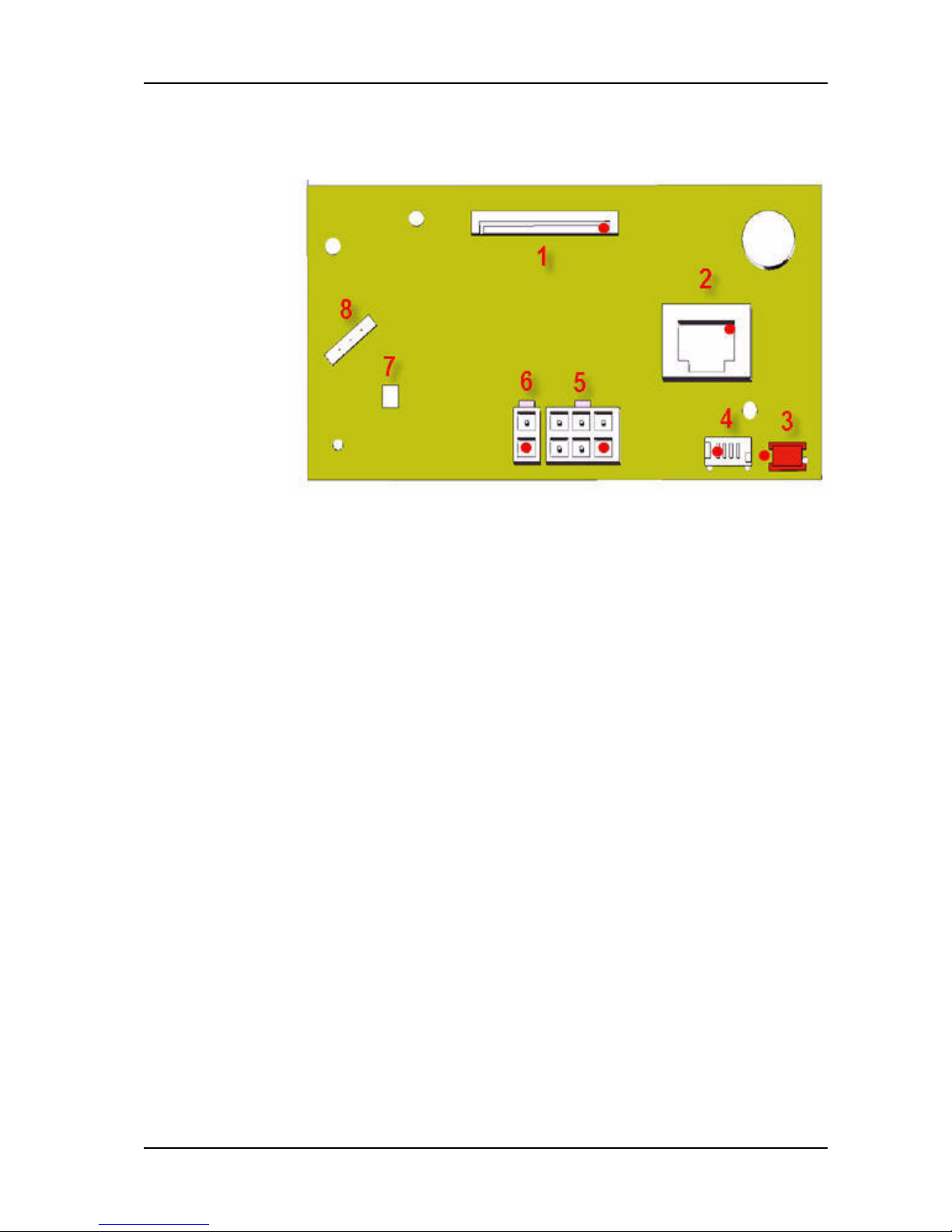
6.2.3.2 Connections
Picture 7: Power electronics connector
Page 70

GTS Technical Manual
19. April 2010 Edition: V1.00/2010 6-12
Copyright © 2010, Diversey Inc.
06.0 swingo 1255 B Power - electronics.fm
Pos. Plug Description [plug] Pin Description [pin]
1 X15 Brush motor - Minus (-) 1 Minus (-)
2 X13 Brush motor - Plus (+) 1 Plus (+)
3 X14 Battery - 24V 1 24V
4 X16 Battery - GND 1 GND
5X1Drive motor 1Minus (-)
5X1Drive motor 2Plus (+)
6 X2 Vacuum motor 1 Plus (+)
6 X2 Vacuum motor 2 Minus (-)
7 X8 Emergency loop 1 Emergency loop - IN
7 X8 Emergency loop 2 Emergency loop - OUT
8 X12 External hour counter (Optional) 1 Plus (+)
8 X12 External hour counter (Optional) 2 Minus (-)
9 X17 TASKI J-FIT (Optional) 1 Power On
9 X17 TASKI J-FIT (Optional) 2 Power On
9 X17 TASKI J-FIT (Optional) 3 PWM J-FIT OUT
9 X17 TASKI J-FIT (Optional) 4 GND
10 X9 USB port 1 VCC USB
10 X9 USB port 2 Minus (-)
10 X9 USB port 3 Plus (+)
10 X9 USB port 4 GND
Table 2: Power electronics connector description
Page 71

GTS Technical Manual
19. April 2010 Edition: V1.00/2010 6-13
Copyright © 2010, Diversey Inc.
06.0 swingo 1255 B Power - electronics.fm
10 X9 USB port 5 (Housing) GND
11 X7 Communication 1 Throttle
11 X7 Communication 2 Serial - OUT
11 X7 Communication 3 Serial - CLK
11 X7 Communication 4 Serial - LATCH
11 X7 Communication 5 Serial - IN
11 X7 Communication 6 Start signal
11 X7 Communication 7 +5V
11 X7 Communication 8 GND
11 X7 Communication 9 (Housing) GND
11 X7 Communication 10 (Housing) GND
12 X18 Electrical brush drive unit 1 Motor Plus (+)
12 X18 Electrical brush drive unit 2 Motor Minus (-)
12 X18 Electrical brush drive unit 3 EBU internal switch (not connected)
12 X18 Electrical brush drive unit 4 EBU internal switch
12 X18 Electrical brush drive unit 5 Brush position switch (Transport = Closed)
12 X18 Electrical brush drive unit 6 Minus (-)
13 X4 Pump 1 1 Duty cycle Pump 1 (1255)
13 X4 Pump 2 2 Duty cycle Pump 2 (755/855 and 1255)
13 X4 Filter 24V 3 Plus (+)
Pos. Plug Description [plug] Pin Description [pin]
Table 2: Power electronics connector description
Page 72

GTS Technical Manual
19. April 2010 Edition: V1.00/2010 6-14
Copyright © 2010, Diversey Inc.
06.0 swingo 1255 B Power - electronics.fm
13 X4 Pumps/Filter 24V 4 GND (1255)
13 X4 Pumps/Filter 24V 5 GND (755/855 and 1255)
13 X4 Pumps/Filter 24V 6 GND (Valve)
Pos. Plug Description [plug] Pin Description [pin]
Table 2: Power electronics connector description
Page 73

GTS Technical Manual
19. April 2010 Edition: V1.00/2010 6-15
Copyright © 2010, Diversey Inc.
06.0 swingo 1255 B Power - electronics.fm
6.2.4 Charger
Picture 8: Charger
The DK charger model corresponds to the protection class II and is
therefore slightly different constructed.
6.2.4.1 Replacing of charger
Remove
• Unlock battery compartment by removing screws of locking
system.
• Open the battery compartment.
• Disconnect the wires for mains at the connection block on the
chassis.
• Disconnect the plug for communication.
• Remove the two nuts (04/104)
• Remove charger.
Make sure that you hold the charger when loosening the nuts.
Mount
• Position the new charger.
• Mount the two nuts.
• Connect the plug for communication.
• Connect the wires for the mains.
• Close and lock the battery compartment on both sides with the
screws of the locking system.
6.2.4.2 Connectors
On the charger itself there are no connectors. The following list describes the connections after the charger. These connections you find placed on the chassis.
Page 74

GTS Technical Manual
19. April 2010 Edition: V1.00/2010 6-16
Copyright © 2010, Diversey Inc.
06.0 swingo 1255 B Power - electronics.fm
Picture 9: Charger wiring
1 Wires directly to the batteries.
2 Connection block mounted on the chassis.
3 8 pole connector placed in the chassis.
Page 75

GTS Technical Manual
19. April 2010 Edition: V1.00/2010 6-17
Copyright © 2010, Diversey Inc.
06.0 swingo 1255 B Power - electronics.fm
Pos. Plug Description [plug] Pin Description [pin]
1 B1 Battery charge (red) 1 Battery charge - Plus (+)
1 B1 Battery charge (black) 2 Battery charge - Minus (-)
2S3Power main cord 1Phase
2S3Power main cord 2Neutral
2S3Power main cord 3GND
3 X7 Charger communication 1 Not connected
3 X7 Charger communication 2 Not connected
3 X7 Charger communication 3 Emergency loop IN
3 X7 Charger communication 4 Emergency loop OUT
3 X7 Charger communication 5 GND
3 X7 Charger communication 6 Information charge failed
3 X7 Charger communication 7 Information charge
3 X7 Charger communication 8 Information charged
Table 3: Charger connector description
Page 76
GTS Technical Manual
19. April 2010 Edition: V1.00/2010 6-18
Copyright © 2010, Diversey Inc.
06.0 swingo 1255 B Power - electronics.fm
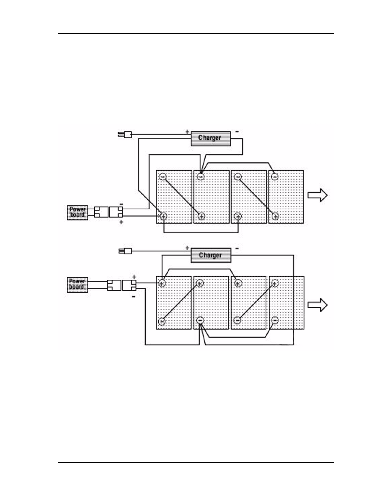
6.3 Schematics/System
6.3.1 Battery connection
Picture 10: Battery connection
Page 77

GTS Technical Manual
19. April 2010 Edition: V1.00/2010 6-19
Copyright © 2010, Diversey Inc.
06.0 swingo 1255 B Power - electronics.fm
6.3.2 Electrical schematic
Picture 11: Electrical schematic
Page 78

19. April 2010 Edition: V1.00/2010
Copyright © 2010, Diversey Inc.
Technical Manual
7 Additional information
Page 79

GTS Technical Manual
19. April 2010 Edition: V1.00/2010 7-2
Copyright © 2010, Diversey Inc.
10.0 swingo 1255 - additional information.fm
7 Additional information
7.1 Available GTS Newsletter/Instructions
Newsletter Date of is-
sue
Topic/Modification Ma-
chine
version
Serial
number
Tool SKU tool
Table 1: Newsletters/Instructions
Page 80

19. April 2010 Edition: V1.00/2010
Copyright © 2010, Diversey Inc.
Technical Manual
8 Revision
Page 81

GTS Technical Manual
19. April 2010 Edition: V1.00/2010 8-2
Copyright © 2010, Diversey Inc.
11.0 swingo 1255 B Power - revision.fm
8Revision
Date Chapter Content Description Revision
Table 1: Revision
Page 82

19. April 2010 Edition: V1.00/2010
Copyright © 2010, Diversey Inc.
Technical Manual
9 Appendix
Page 83

GTS Technical Manual
technical manual swingo 1255 B Power V1.00 2010.03MIX.fm
19. April 2010 Edition: V1.00/2010
Copyright © 2010, Diversey Inc.
Glossar
A
Accessories 4-9
Additional 4-8
Additional information 7-2
Additional parts 4-9
B
Back blade 5-15
Batteries 3-2
Battery 4-6
Battery compartment 4-6
Battery connection 6-18
Battery specifications 4-6
Brush belt - New setup 5-30
Brush drive 5-30
Brush drive unit 5-28
Brush pulley 5-33
Brush System 4-7
C
Castor wheel 5-18
Charger 4-7, 6-15
Conclusion 1-3
Connections 6-5, 6-11
Connectors 6-15
Consumable supplies 3-2
D
Dash board service menu 6-9
Dashboard 6-4
Dimensions and weights 4-4
Direction description 3-2
Drive, wheel group 5-22
E
Electrical brush unit 5-27
Electrical schematic 6-19
Electrical sequences 6-4
Electronic sequences 6-2
Elementary 2-2
Emergency loop 6-3
ESD 2-2
F
Filter 24V 5-19
Fixation spring 5-13
Foot lever 5-24
Foreword 1-2
Front blade 5-14
G
General 3-2, 6-2
H
Hall sensor board 5-3
Handle/Upper part 5-2
Health & Safety 2-2
I
Intermediate pulley 5-37
L
Linear drive distance EBU 5-27
Lower part & tank 5-16
M
Machine Profile 4-3
Machine range 4-2
Machine speed 4-4
Material 3-3
Mechanical sequences 5-2
Microswitch 5-2
Motor 5-35
Motor belt 5-35
N
Newsletter/Instructions 7-2
P
Part reference 3-2
Power electronics 6-10
Pump 5-20
Pusher rack 5-24, 5-26
Pusher rack distance 5-26
Page 84

GTS Technical Manual
technical manual swingo 1255 B Power V1.00 2010.03MIX.fm
19. April 2010 Edition: V1.00/2010
Copyright © 2010, Diversey Inc.
R
Required material 3-3
Reset service LED 6-9
Revision 8-2
S
Schematics 6-18
Squeegee 5-13
Squeegee bracket spring 5-11
Squeegee lowering 5-11
Suction power 4-8
swinging arm long 5-12
System 6-18
System architecture 6-2
System overview 6-2
T
Tank 5-16
Tank cover 5-8
Target 1-2
Technical Data 4-2
Technical data 4-3
Technical Information 4-3
Technical Manual 1-2
Technical Training 1-2
Throttle lever 5-5
Tool lowering unit 5-24
Tools 3-3
Traction unit 5-22
V
Vacuum motor 5-6
Page 85

19. April 2010 Edition: V1.00/2010
Copyright © 2010, Diversey Inc.
Technical Manual
10 Notes
Page 86

Ersatzteilliste
Liste des pièces de rechange
Spare parts list
TASKI swingo 1255 B
Ausführung/Execution; List(e) /1
30.03.2010 SPS
Postfach CH---9542 Münchwilen
Telefon +41 71 969 27 27 Fax +41 71 969 22 53
Page 87

TASKI swingo 1255B
Modell -- Uebersicht
Résumé des différents modèles
Overview for the versions
WD Radantrieb Wheel drive
CSD Dosiersystem Cleaning Solution Dosing
BMS Battery Management System Battery Management System
EBU Elektrische Bürstenabsenkung Electric Brush Unit
TASKI swingo
Type WD CSD BMS EBU Serie
7517715 1255 B Power BMS NA CO1255.1C X X X 01
7516829 1255 B Power CO1255.1 X X 01
7517575 1255 B Power BMS DK CO1255.1X X X X 01
7517576 1255 B Power BMS EBU DK CO1255.2X X X X X 01
7516834 1255 B Power BMS EBU EURO CO1255.2X X X X X 01
7516832 1255 B Power BMS EBU SEV CO1255.2X X X X X 01
7516831 1255 B Power BMS EURO CO1255.1X X X X X 01
7516830 1255 B Power BMS SEV CO1255.1X X X X 01
7516833 1255 B Power BMS UK CO1255.1X X X X X 01
7516836 1255 B Power EBU CO1255.2 X X X 01
Page 88

1
TASKI swingo 1255B
S007387 TASKI swingo 1255B TASKI swingo 1255B TASKI swingo 1255B
Pos.
No.
Artikelnr.
Article No.
Item No.
Bestellnr.
No. de com
Order No.
Model
Stck.
Piè.
Qty.
Bezeichnung Designation Description
1 S007388 1.00 Oberteil Partie supérieure Upperpart
2 S007389 1.00 Düsenabsenkung Dispositif remontèe suceur Squeegeelowering mechanism
3 S007390 1.00 Saugdüse Suceur Squeegee
4 S007391 1.00 Unterbau Partie intérieure Lower part
5 S007392 1.00 Radantrieb mit Motor Entraînement avec moteur Drive with motor
6 S007393 1.00 Bürstenabsenkung Dispositif des brosses Tool lowering unit
7 S007394 1.00 Bürstenantrieb Entraînement des brosses Brush drive
8 S007395 1.00 Schlauchleitungen Tubes Tube lines
9 S007396 1.00 Tank, Schläuche, Ventil/Filter Réservoir,Tubes,soupape/filtre Tank,Tubes,valve/filter
10 S007397 1.00 Diverse Ersatzteile Pièces détachées diverses Various spare parts
11 S007398 1.00 Elektroschema Schéma electrique Electrical diagram
Page 89

2
TASKI swingo 1255B
S007388 Oberteil Partie supérieure Upper part
Pos.
No.
Artikelnr.
Article No.
Item No.
Bestellnr.
No. de com
Order No.
Model
Stck.
Piè.
Qty.
Bezeichnung Designation Description
101 17621-- 15 4129049 1.00 Elektronik--Set 755B Power Kit Tableau de commande électro Dash Board Electronic Set 755B
102 17605--23 4122779 7516829 1.00 Überbrückung Wegfahrsperre Contact de pontage Jumper
102 17605-- 23 4122779 7516836 1.00 Überbrückung Wegfahrsperre Contact de pontage Jumper
103 1840/051 4122641 7.00 Delta PT--Schr LK As Torx 40x16 Vis Delta PT Torx 40x16 Screw Delta PT Torx 40x16
104 17701-- 38 4127397 1.00 Deckel Couvercle Cover
105 17602-- 74 4122618 1.00 Griff Poignée Handle
106 1840/050 4122639 6.00 Delta PT--Schr LK As Torx 60x20 Vis Delta PT Torx 60x20 Screw Delta PT Torx 60x20
107 1840/110 4122829 6.00 Delta PT--Schr LK Torx 60x35 Vis Delta PT Torx 60x35 Screw Delta PT Torx 60x35
108 17701-- 47 4127869 1.00 Lappen Plaque de protection Protection Shield
109 1987/5 4019900 4.00 Spreizniet 4,5x10 Rivet à ecarter 4,5x10 Retaining Rivet 4,5x10
110 17608--96 4126719 2.00 Halter Goujon de retenue Retaining Pin
112 17604--58 4122676 1.00 Lagerring Entretoise de guidage Guide Ring
113 1840/052 4122655 9.00 Delta PT--Schr LK As Torx 50x16 Vis Delta PT Torx 50x16 ScrewDelta PT Torx 50x16
114 4212/1 4010480 1.00 Kabelbride Bride pour câble Cable Clamp
115 8401/180 4094580 1.38m 1.00 Dichtungsband 10x5 Bande d’étanchéité 10/5 le m Seal Strip 10/5 H2442 Per M
116 17609--00 4126808 1.00 Saugerplatte 1250 Plaque de base 1250 Base Plate 1250
117 17606--54 4122750 2.00 Puffer Verrouillage Lock
118 8662/010 4122571 1.69m 1.00 Dichtprofil Joint d’étanchéité profilé Sealing Profile
120 4991/105 4075260 OPTION 1.00 Stundenzähler 24V DC Compteur horaire Working Hour Meter
121 4677/236 4123132 1.00 Motorturbine 24V 491W 17,4A Turbine24V Vacuum Motor 24 V
123 17605--41 4122621 1.00 Manschette Manchette Sealing Ring
124 4016/232 4082740 1.00
Klemmenleiste 2--Pol 6 mm@
Serre--fils 2--pôles Connection Bloc 2--Ways
125 17620-- 65 4128326 1.00 Tankdeckel 1255 Couvercle de réservoir Tank Cover
126 17603-- 80 4122807 1.00 Tankriegel kurz Verrouillage Lock Lever
127 17620-- 58 4128295 1.00 Deckelstütze Etrier support SupportBar
128 17600-- 35 4122552 1.00 Saugerfilter Filtre Filter
129 17602-- 08 4122553 1.00 Schwimmer Flotteur Floating Unit
130 17605-- 52 4122680 1.00 Schutzkragen Plaque de protection Protection Plate
131 17608-- 82 4126721 1.00 Druckscheibe Rondelle de pression PressureWasher
132 17605-- 91 4122682 2.00 Dichtring Anneau d’étanchéité Sealing Ring
135 17603-- 86 4122573 1.00 Schaltmechanik Mécanique de commande Mechanic Hall Sensor Compl.
136 17604-- 00 4122731 2.00 Bolzen Goujon Bolt
137 17603-- 94 4122575 2.00 Faltenbalg Soufflet d’intercirculation Bellows
138 17603-- 21 4122732 2.00 Raster Levier à cran Grid Lever
139 2803/110 4122733 2.00 Druckfeder 0,8/7,1x33 Ressort de pression 7,1x33 Pressure Spring 0,8/7,1x33
140 17603-- 37 4122734 2.00 Schwenkhebel Levier de commande Switch Lever
141 4501/119 4124476 1.00 Microschalter Interrupteur Microswitch
142 17605-- 40 4122678 1.00 Dämpfung Isolation phonique Noise Absorbing Plate
145 4850/102 4108430 1.00 Ferrit--Ringkern 16.5/8x28 Self à noyau torique 16,5/8 Toroidal Choke 16,5/8x28
146 17701-- 46 4127860 1.00 Deckel Couvercle Cover
-- 1.00 -- -- -4215/116 4065440 1.00 Kabelbinder 100 Bande à lier les câbles 85 mm Cable Tie 85 mm
Page 90

S0073883 TASKI swingo 1255B
103
swingo 1255 B /1
01
a)
a)
104
105
106
101
102
107
109
130
132
106
113
123
125
126
142
121
112
113
113
114
116
127
106
135
117
118
136
137
138
139 140
129
128
110
103
115
108
131
124
107
(Gr.10 P.113)
145
141
146
120
Page 91

4
TASKI swingo 1255B
S007389 Düsenabsenkung Dispositif remontèe suceur Squeegee lowering
mechanism
Pos.
No.
Artikelnr.
Article No.
Item No.
Bestellnr.
No. de com
Order No.
Model
Stck.
Piè.
Qty.
Bezeichnung Designation Description
101 17620-- 47 4128231 1.00 Düsenarm lang Brasde pivotement long Swinging Arm Long
102 17620-- 48 4128232 1.00 Achse Axe Axle
103 1132/186 4065050 2.00 Zyl--Schr I--6Kt M8x12 Vis cyl. à trou 6 p. M 8x12 Socket Head Cap Screw M 8x12
104 17620-- 50 4128234 2.00 Bolzen Goujon Bolt
105 2804/105 4128743 1.00 Druckfeder 5,6/33,6x66 Ressort de pression 5,6/33,6x66 Pressure Spring 5,6/33,6x66
106 2511/107 4126535 6.00 Gleitlager 8/10/15x5.5 Coussinet 8/10/15x5,5 Slide Bearing 8/10/15x5,5
107 1142/175 4126662 1.00 Zyl--Schr I--6Kt M10x40 Vis cyl. à trou 6 p. M 10x40 Socket Head Cap Screw M 10x40
108 17620-- 89 4128598 1.00 Gleitlager 28/32/42x14 Coussinet 28/32/42x14 Slide Bearing 28/32/42x14
109 17608-- 76 4126609 1.00 Distanzscheibe 10.5/42 Disque 10.5/42 Washer 10.5/42
110 17701--55 4127926 1.00 Fusshebelschutz Pédale Foot Lever
111 17620--51 4128235 1.00 Düsenarm Bras de pivotement Swinging Arm
112 17620--49 4128233 2.00 Achse Axe Axle
113 2913/148 4058370 4.00 Sicherungsscheibe Welle 6x0,7 Anneau de sûreté p. arbre 6 Circlip For Shaft 6
114 2807/007 4128597 1.00 Zugfeder 2.8/20/95.8 Ressort de tension 2.8/20/95.8 Tension Spring 2.8/20/95.8
115 1721/7 4031060 1.00 Sicherungsmutter M10 ÉcroudesuretéM10 Self--Locking Nut M 10
116 17620--52 4128236 1.00 Buchse Douille Bush
117 8936/1 4017370 1.00 Sicherungs--Klebstoff mittel Colle p. blocage moyen 50 gr Adhesive Locking Middle 50Gr
118 8906/106 4122242 1.00 Getriebefett OKS 427, 1Kg Graisse --engrenage,palier 1Kg Lubricant -- Gear,Bearing 1 Kg
Page 92

S0073895 TASKI swingo 1255B
02
swingo 1255 B /1
A)
107
105
110
113
101
112
103
106
111
106
104
104
114
A)
117
115
108
109
116
118
60Nm
(Gr.04)
102
Page 93

6
TASKI swingo 1255B
S007390 Saugdüse Suceur Squeegee
Pos.
No.
Artikelnr.
Article No.
Item No.
Bestellnr.
No. de com
Order No.
Model
Stck.
Piè.
Qty.
Bezeichnung Designation Description
101 17620-- 44 4128213 1.00 Saugdüse lang Suceur longe Squeegee Long
-- 1.00 -- -- --
-- 1.00 -- -- -102 1129/187 4043000 2.00 Zyl--Schr I--6Kt Nk M8x45/22 Vis cyl. à trou 6 p. M 8x45 Socket Head Cap Screw M 8x45
103 1747/15 4007400 2.00 Unterlagscheibe 8,4/16x1,6 Rondelle 8,4/16 Washer 8,4/16
104 17606-- 69 4122783 2.00 Rad Roue Wheel
105 17606-- 74 4122839 2.00 Stützscheibe Rondelle d’appui Sustaining Disc
106 1790/15 4007890 2.00 Wellenscheibe 14/21,8x0,3 Entretoise 14/21,8 Waved Washer 14/21,8
107 18508-- 95 4121923 2.00 Bundbuchse 8,4/12/22x33 Douille Bush
108 17620-- 57 4128294 1.00 Spannschiene HM lang Bande de serrage long Tightening Strap Long
109 17620-- 32 4128161 1.00 Spannschiene HL kurz Bande de serrage court Tightening Strap Short
110 1759/12 4022860 2.00 Unterlagscheibe 5,3/10x1 Rondelle 5,3/10 Washer 5,3/10
111 1134/154 4123155 2.00 Zyl--Schr I--6Kt M5x35 Vis cyl. à trou 6 p. M 5x35 Socket Head Cap Screw M 5x35
112 1425/134 4122652 2.00 L--SchrI--6Kt mit Flansch M8x20 Vis à tête bomb.flasque M8x20 Flange Sock.Head Screw M 8x20
113 17620--74 4128507 1.00 Absatz Gradin Offset
114 17620--36 4128166 1.00 Arretierfeder Ressort d’arrêt Click Spring
115 1721/7 4031060 2.00 Sicherungsmutter M10 ÉcroudesuretéM10 Self--Locking Nut M 10
116 1752/16 4027970 2.00 Unterlagscheibe 10,5/20x2 Rondelle 10,5/21 Washer 10,5/21
117 17620--33 4128163 1.00 Spannschiene HR kurz Bande de serrage court Tightening Strap Short
118 18603--19 4127629 1.00 Rad 64/24 Roue 64/24 Wheel 64/24
119 18603--30 4127883 1.00 Achse Axe Axle
120 1852/150 4107130 2.00 Gew--Form--L--Schr Torx M5x12 Vis autofiletage M 5x12 Self--Thread--Form.Screw M 5x12
121 17620-- 43 4128209 1.00 Düsenkörper lang Corpe de suceur long Squeegee Body Long
122 12200-- 36 4122536 1.00 Lamelle 56/4,5x858 Lamelle Blade
123 12200-- 35 4122535 1.00 Lamelle 56/3x816 Lamelle Blade
124 17620-- 56 4128293 1.00 Spannschiene V lang Bande de serrage long Tightening Strap Long
129 2036/131 4128657 2.00 Lenkrolle kompl. 50/20 Roulette pivotante compl. 50/20 Castor Compl. 50/20
-- 1.00 -- -- --
-- 1.00 -- -- --
-- 1.00 -- -- --
130 12200-- 48 4127052 OPTION 2.00 Lamelle 56/2,5x858 Lamelle 56/2,5x858 Blade 56/2,5x858
130 12200-- 56 4127204 OPTION 1.00 Lamelle 56/3x816 Blade 816 Lamelle 816
Page 94

S0073907 TASKI swingo 1255B
03
swingo 1255 B /1
103
104
105
106
107
102
109
110
111
121
123
108
122
117
118
119
120
129
101
112
113
114
115
116
124
Page 95

8
TASKI swingo 1255B
S007391 Unterbau Partie intérieure Lower part
Pos.
No.
Artikelnr.
Article No.
Item No.
Bestellnr.
No. de com
Order No.
Model
Stck.
Piè.
Qty.
Bezeichnung Designation Description
101 17601-- 08 4122628 1.00 Chassis 1250 Châssis CO 1250 Chassis CO 1250
102 1014/208 4122658 1.00 6Kt--Schr M12x55/30 Vis à tête six pans M12x55/30 Hexagon Screw M 12x55/30
103 17602-- 79 4122656 1.00 Verstärkungsplatte Profil de renforcement Reinforcement Plate
104 1721/106 4092870 2.00 Sicherungsmutter M6 ÉcroudesuretéM6 Self--Locking Nut M 6
105 1752/58 4007490 2.00 Unterlagscheibe 6,4/18x1,6 Rondelle 6,4/18 Washer 6,4/18
106 17609-- 02 4126957 1.00 Träger Leistungsteil Support Support
107 1840/052 4122655 7.00 Delta PT--Schr LK As Torx 50x16 Vis Delta PT Torx 50x16 Screw Delta PT Torx 50x16
108 17607-- 92 4123095 1.00 Klammer 1250 Crampon Clamp
109 1425/134 4122652 2.00 L --Schr I--6Kt mit Flansch M8x20 Vis à tête bomb.flasque M8x20 Flange Sock.Head Screw M 8x20
110 17607--75 4122990 1.00 Lagerplatte kompl. Plaque d’appui Bracket
111 17603--83 4122600 1.00 Lenkrolle kompl. 100/2x31 Roue d’appui 100, 2x31 Swivelling Wheel 100, 2x31
111a 17605-- 71 4122527 1.00 PU--Rollen Set braun Kit, 2 roues 100 brun Set,2 Castor Wheels 100 Brown
112 1840/050 4122639 4.00 Delta PT--Schr LK As Torx 60x20 Vis Delta PT Torx 60x20 ScrewDelta PT Torx 60x20
113 10140--4 4001020 1.00 Bride Bridedecâble Cable Clamp
114 4016/203 4047410 1.00
Klemmenleiste 3--Pol 2.5 mm@
Serre--fils 3--pôles Connection Bloc 3--Ways
115 17608--32 4123176 3.00 Kabelbride Bride Clamp
116 17620--87 4128592 1.00 Ladegerät 20A Chargeur 20A Charger 20A
116 17621--57 NA 1.00 Ladegerät Chargeur Charger
116a 17609--16 4127152 DK 1.00 Ladegerät 25A Chargeur 25A Charger 25A
117 17620--81 4128534 Euro 1.00 Netzkabel 2L+P Euro Câble d’alimentation 2L+P Euro Main Cord 2L+P Euro
117 17620--82 4128560 SEV 1.00 Netzkabel 2L+P SEV Câble d’alimentation 2L+P SEV Main Cord 2L+P SEV
117 17620--83 4128561 UK 1.00 Netzkabel 2L+P UK Câble d’alimentation 2L+P UK Main Cord 2L+P UK
117 17607--69 4122977 DK 1.00 Netzkabel 2L Euro Câble d’alimentation Euro Main Cord Euro
118 4326/250 4127946 EXE. 2008 1.00 Kleinsicherung 6,3A träg Fusible fin retardé 6,3 A Fine--Wire Fuse 6,3 A Slow--Blow
121 17608-- 33 4123169 1.00 Pumpe 24V 25W Pompe24V Pump 24 V
122 17602-- 77 4122754 1.00 Pumpenhalter Fixation de pompe Pump Holder
123 17620-- 69 4128341 1.00 Leistungsteil Power Électronique Power Power Electronics
124 4326/112 4122605 1.00 Feinsicherung träg 315mA 5x20 Fusible fin retardé 315 mA Fine--Wire Fuse 315 mA Slow--Blow
125 1132/145 4060500 2.00 Zyl--Schr I--6Kt M5x10 Vis cyl. à trou 6 p. M 5x10 Socket Head Cap Screw M 5x10
126 1771/55 4007660 2.00 Fächerscheibe 5,1 Rondelle étoile 5,3 Serrated Lock Washer 5,3
127 1752/12 4007460 2.00 Unterlagscheibe 5,3/10x1 Rondelle 5,3/10 Washer 5,3/10
128 1132/19 4006420 1.00 Zyl--Schr I--6Kt M6x10 Vis cyl. à trou 6 p. M 6x10 Socket Head Cap Screw M 6x10
129 1771/56 4007670 1.00 Fächerscheibe 6.4 Rondelle étoile 6,3 Serrated Lock Washer 6,3
130 1752/14 4007470 1.00 Unterlagscheibe 6,4/12x1,6 Rondelle 6,4/12,5 Washer 6,4/12,5
131 1132/5 4006410 1.00 Zyl--Schr I--6Kt M4x10 Vis cyl. à trou 6 p. M 4x10 Socket Head Cap Screw M 4x10
132 1771/54 4007650 1.00 Fächerscheibe 4,3/8x0,5 Rondelle étoile 4,3 Serrated Lock Washer 4,3
133 1752/10 4007440 1.00 Unterlagscheibe 4,3/ 9x0,8 Rondelle 4,3/9 Washer 4,3/9
134 17607-- 07 4122941 1.00 Batteriewanne 1250 Cuvette Tray
135 1810/125 4124672 4.00 Pan--Hd Spanpl--Schr Torx 3.5x20 Vis à tête fraisée KS 3,5x20 Pan Head Tapp.Screw KS 3,5x20
136 18601-- 98 4126822 1.00 Distanzhalter Set Kit piêces des distance Spacer Set
Page 96

S0073919 TASKI swingo 1255B
04
swingo 1255B /1
102
103
104
105
110
112
107
101
116
113
135
112
117
111a
70 Nm
135
111
118
109
115
106
107
123
Ausf. /exe. POWER
107
125 126 127
125
126
127
128 129 130
131 132 133
5Nm
2,5 Nm
7Nm
5Nm
(Gr. 08 P. 120)
134
122
121
114
Ausf. /exe. DK
116a
Battery
136
Page 97

10
TASKI swingo 1255B
S007392 Radantrieb mit Motor Entraînement avec moteur Drive with motor
Pos.
No.
Artikelnr.
Article No.
Item No.
Bestellnr.
No. de com
Order No.
Model
Stck.
Piè.
Qty.
Bezeichnung Designation Description
101 1010/186 4122005 2.00 6Kt--Schr M8x16 Vis à tête six pans M 8x16 Hexagon Screw M 8x16
102 17602-- 92 4122700 2.00 Radscheibe Couvercle Cover
103 17602-- 65 4122588 2.00 Rad 200/50 Roue de commande 200 Drive Wheel 200
103a 17608--40 4123154 OPTION 2.00 Rad 200/45 mit Buchse Roue PU souple Wheel PU Soft
103a 17605--10 4122526 OPTION 2.00 Antriebsrad PU Roue de commande PU Traction Wheel PU
104 17603-- 28 4122599 1.00 Radantrieb Moto--réducteur Drive Unit
105 17608-- 15 4123188 2.00 Brücke Plaque de serrage Bracket
106 1840/004 4109990 STANDARD 4.00 Delta PT--Schr LK As Torx 60x25 Vis Delta PT Torx 60x25 Screw Delta PT Torx 60x25
106 1840/004 4109990 EBU 2.00 Delta PT--Schr LK As Torx 60x25 Vis Delta PT Torx 60x25 Screw Delta PT Torx 60x25
107 17608-- 13 4123112 STANDARD 2.00 Wippe Support flottant Cradle
107 17608-- 13 4123112 EBU 1.00 Wippe Support flottant Cradle
108 17605-- 97 4122736 EBU 1.00 Wippe EBU Support flottant Cradle
109 2201/196 4122759 2.00 Federkeil 6/6x45 Clavette 6/6x45 Key 6/6x45
110 17606--38 4122737 EBU 1.00 Scheibe 50/75x3 Disque Disc
111 1132/23 4006450 EBU 2.00 Zyl--Schr I--6Kt M6x20 Vis cyl. à trou 6 p. M 6x20 Socket Head Cap Screw M 6x20
112 1752/14 4007470 EBU 2.00 Unterlagscheibe 6,4/12x1,6 Rondelle 6,4/12,5 Washer 6,4/12,5
113 8909/61 4039680 Synthesefett Syn 53B, 1Kg Lubrifiant synsetral 53B P Kg Lubricant Synsetral 53B P Kg
114 4850/105 4122229 1.00 Ferrit--Ringkern 26/13x28.5 Self à noyau torique 26/13 Toroidal Choke 26/13x28,5
115 3395/100 4123190 1.00 Kohlebürsten Set Kit balai charbon (2 pcs.) Carbon Brush Set (2 pcs.)
-- -- -- --
4215/3 4023260 2.00 Kabelbinder 200 Bande à lier les câbles 200 mm Cable Tie 200 mm
Page 98

S00739211 TASKI swingo 1255B
05
Ausf./Exe. : EBU
swingo 1255 B /1
109
104
103
102
101
101 102 103
108
107
110
105
106
107
111
112
Option !
103a
105
113
114
-
+
-
+
Charger
Charger
Power
board
Power
board
+
-
+
-
+
-
+
-
+++
- - -
- - -
+ + +
115
Batterie--Verbindungen
Batteries connections
Connectionnes des batteries
Page 99

12
TASKI swingo 1255B
S007393 Bürstenabsenkung Dispositif des brosses Tool lowering unit
Pos.
No.
Artikelnr.
Article No.
Item No.
Bestellnr.
No. de com
Order No.
Model
Stck.
Piè.
Qty.
Bezeichnung Designation Description
101 17609-- 04 4127002 1.00 Fusspedal Patin à pédale Pedal Pad
102 17620-- 96 4128702 1.00 Fusshebel Pédale Food Level
103 1840/052 4122655 4.00 Delta PT--Schr LK As Torx 50x16 Vis Delta PT Torx 50x16 Screw Delta PT Torx 50x16
104 17605-- 01 4122692 1.00 Kulisse Coulisse Gate
105 2806/407 4055460 1.00 Zugfeder 1,25/13,7x80 Ressort de tension 13,7x80 Tension Spring 13,7x80
106 17608-- 00 4123098 1.00 Stange Barre de compression Pusher Rack
107 17609-- 06 4127049 1.00 Bolzen Goujon Bolt
108 1936/110 4127048 1.00 Vorsteckfeder 2 Goupille ressort Stop Pin
109 17602-- 28 4122694 2.00 Bolzen Axe Axle
110 2911/113 4064740 4.00 Sicherungsring 15x1 A Rondelle ”seeger” 15 A RetainingRing 15 A
111 17601--78 4122697 1.00 Bolzen Axe Axle
112 2913/110 4060910 3.00 Sicherungsscheibe f. Welle 8x1 Anneau de sûreté p. arbre 8 Circlip For Shaft 8
113 2505/618 4085250 1.00 Gleitlager 15/17/23x12 Coussinet 15/17/23--12 Slide Bearing 15/17/23--12
114 17604--52 4122741 1.00 Bolzen Axe Axle
115 17603--06 4122739 2.00 Bolzen Axe Axle
115 17603--06 4122739 EBU 3.00 Bolzen Axe Axle
116 17604--62 4122742 1.00 Hebel Lang Levier Lever
117 1840/051 4122641 1.00 Delta PT--Schr LK As Torx 40x16 Vis Delta PT Torx 40x16 ScrewDelta PT Torx 40x16
118 17605--30 4122743 1.00 Microschalter mit Litzen Interrupteur de fin de course Limit Switch
119 17604--85 4122699 2.00 Bolzen Axe Axle
120 2910/7 4020050 4.00 Sicherungsring 8x0,8 A Rondelle ”Seeger” 8 A Retaining Ring 8 A
121 17608-- 31 4125883 1.00 Bolzen Goujon Bolt
130 17602-- 86 4122589 1.00 Linearantrieb 24V 43mm Mécanisme élévateur Linear Drive
134 2910/7 4020050 2.00 Sicherungsring 8x0,8 A Rondelle ”Seeger” 8 A Retaining Ring 8 A
136 17606-- 40 4122738 1.00 Spezial Schraube Visspéciale Special Screw
137 1654/7 4007200 1.00 SechskantmutterM8 Écrou à six pans M 8 Hexagon Nut M 8
138 8936/1 4017370 Sicherungs--Klebstoff mittel Colle p. blocage moyen 50 gr Adhesive Locking Middle 50Gr
Page 100

S00739313 TASKI swingo 1255B
06
101
swingo 1255 B /1
M6
!
!
a)
a)
102
105
118
117
110
103
104
107
106
119
120
109
111
115
114
112
110
116
112
107
137
138 113
130
136
Ausf./Exe. : EBU
112
(Gr.07,P.146)
287mm
+
--
1
330mm
43mm
134
381mm
110
(Gr.05)
115
121
108
108
für Demontage
For Demounting
 Loading...