


Edition: V1.00/2014
Technical Manual
To Order Parts Call 1-888-702-5326 - https://monsterfloorequipmentparts.com

GTS Technical Manual
tecnical manual procarpet 30_V1.00IVZ.fm
14. March 2014 Edition: V1.00/2014
Copyright © 2014, Diversey Care
Index
1Forward
1.1 Target 1
1.2 Technical Training 1
1.3 Technical Manual 1
1.4 Summary 2
2Elementary
2.1 Health & Safety 1
2.2 ESD 1
3 General
3.1 General information 1
3.1.1 Part reference 1
3.1.2 Consumable supplies 1
3.1.3 Direction description 1
3.1.4 Power source 1
3.2 Required material 2
3.2.1 Tools 2
3.2.2 Material 2
4Technical data
4.1 Machine range 1
4.2 Technical information 2
4.2.1 Machine profile 2
4.2.2 Technical data 2
4.2.3 Dimensions and weights 3
4.2.4 Brush system 4
4.2.5 Suction power 4
4.3 Accessories & Additional parts 4
4.3.1 Accessories 4
5 Mechanical
5.1 Handle 1
5.1.1 Removing of housing 1
5.1.2 Mounting of housing 2
5.1.3 Removing of microswitch 3
5.1.4 Mounting of microswitch 5
5.1.5 Removing of switching bow 6
5.1.6 Mounting of switching bow 7
5.2 Tank cover and tank 8
5.2.1 Removing of fresh water tank assembly 8
5.2.2 Mounting of fresh water tank assembly 10
5.3 Brush & Motor 12
5.3.1 Removing of brush motor belt 12
5.3.2 Mounting of brush motor belt 13
5.3.3 Removing of brush motor 14
5.3.4 Mounting of brush motor 15
5.3.5 Removing of brush pulley 16
To Order Parts Call 1-888-702-5326 - https://monsterfloorequipmentparts.com

GTS Technical Manual
tecnical manual procarpet 30_V1.00IVZ.fm
14. March 2014 Edition: V1.00/2014
Copyright © 2014, Diversey Care
5.3.6 Mounting of brush pulley 17
5.3.7 Adjusting of brush height 18
5.4 Vacuum unit & squeegee 19
5.4.1 Removing of vacuum motor 19
5.4.2 Mounting of vacuum motor 20
5.4.3 Removing of shackle 21
5.4.4 Mounting of shackle 22
5.4.5 Removing of squeegee 23
5.4.6 Mounting of squeegee 24
5.4.7 Removing of brush level adjustment 25
5.4.8 Mounting of brush level adjustment 27
5.5 Magnetic valve & water outlet 28
5.5.1 Removing of pump 28
5.5.2 Mounting of pump 29
5.5.3 Removing of fresh water filter 30
5.5.4 Mounting of fresh water filter 31
5.5.5 Removing of bypass valve 32
5.5.6 Mounting of bypass valve 33
5.5.7 Removing of valve unit 34
5.5.8 Mounting of valve unit 35
6 Electrical
6.1 System architecture 1
6.1.1 Motor circuit 1
6.2 Main cord & cable inlet inbox 2
6.2.1 Removing of rockingswitch 2
6.2.2 Mounting of rockingswitch 3
6.2.3 Rockingswitch connections 4
6.3 Contactor 6
6.3.1 Removing of contactor 6
6.3.2 Mounting of contactor 7
6.3.3 Contactor connections K1/K2 8
6.3.3.1 Contactor connections K1 9
6.3.3.2 Contactor connections K2 10
6.4 Electrical schematics 11
6.4.1 Electrical schematics 11
7 Additional information
7.1 Available GTS Newsletter/Instructions 1
8Revision
9Appendix
10 Notes
To Order Parts Call 1-888-702-5326 - https://monsterfloorequipmentparts.com

14. March 2014 Edition: V1.00/2014
Copyright © 2014, Diversey Care
Technical Manual
1 Forward
To Order Parts Call 1-888-702-5326 - https://monsterfloorequipmentparts.com

GTS Technical Manual
14. March 2014 Edition: V1.00/2014 1-1
Copyright © 2014, Diversey Care
01.0 TASKI - foreword_V1.00.fm
1 Foreword
1.1 Target
To serve our customers faster and more efficient it is important to achieve a general
standard of technical know how with our partners in the market.
Therefore we developed a Technical Training concept which is based on e-spares. The
concept consists of a Technical Manual and a Technical Training.
These two tools will be produced for each newly launched machine with a certain complexity. The Technical Manual will be available as PDF file and can be downloaded from
e-spares. The Technical Training documentation will be distributed after having attended the technical training.
1.2 Technical Training
The Technical Training is addressed as reference book for the technical training sessions
and will be distributed to the floor care responsible and/or to the technical training responsible after attending a training session provided by GTS (max. 2 persons per country).
The intension is, that after this session, a technical trainer is able to perform technical
training for their local technical staff and in this way to transfer the knowledge to all
service technicians.
The Technical Training is not intended as manual for the service technicians and will be
distributed only to the training responsible of each country.
1.3 Technical Manual
The Technical Manual is addressed to the service technicians and should be translated
and distributed after a technical training.
It contains a summary of procedures, hints and suggestions etc. which are helpful and
To Order Parts Call 1-888-702-5326 - https://monsterfloorequipmentparts.com

GTS Technical Manual
14. March 2014 Edition: V1.00/2014 1-2
Copyright © 2014, Diversey Care
01.0 TASKI - foreword_V1.00.fm
essential for the daily business. The Technical Manual can be downloaded from espares/documents.
1.4 Summary
We are convinced that the Technical Manual concept together with the Technical Training
are powerful tools, which will help our service organisations to achieve a higher level of
quality in repairs and customer satisfaction.
If you have any comments or questions do not hesitate to contact your country responsible.
Sincerely yours
GTS Team
To Order Parts Call 1-888-702-5326 - https://monsterfloorequipmentparts.com

14. March 2014 Edition: V1.00/2014
Copyright © 2014, Diversey Care
Technical Manual
2 Elementary
To Order Parts Call 1-888-702-5326 - https://monsterfloorequipmentparts.com

GTS Technical Manual
14. March 2014 Edition: V1.00/2014 2-1
Copyright © 2014, Diversey Care
02.1 TASKI - elementary_V1.00.fm
2Elementary
2.1 Health & Safety
Scrubber dryers may be powered by mains electricity or batteries. There are risks associated with both, which call for proper precautions, such as the provision of good ventilation and the elimination of risk of ignition.
All work, carried out on such machines, should only be performed by trained personnel
in accordance with local regulations.
Before working on such a machine, isolate it from any electrical power source.
Always wear the required personal protective equipment (including gloves and goggles)
that must be worn when potentially exposed to any hazardous material and when carrying out hazardous tasks.
Note that parts may be contaminated with chemical product. If possible flush hoses out
with fresh water prior to carrying out any maintenance. For information on chemical
products that are used in this machine, please carefully read the product label and Material Safety Data Sheet (MSDS).
Empty water tanks prior to carrying out any maintenance. Ensure contaminated water is
emptied into an approved drain. Avoid pollution.
2.2 ESD
Static electricity is electricity at rest or the accumulation of electric charge, as opposed
to an electric current which is the movement of electricity. The flow or movement of people and/or materials in and through the environment causes separation of electrons and
therefore static electricity. A familiar example of static electricity is when a person walks
across a carpeted floor. Static electricity/electrostatic charge is generated simply by the
contact and separation of the soles of that individual's shoes from the carpeted floor.
Electrostatic Discharge (ESD) occurs when the electrostatic charge is transferred from a
material that carries the charge to an electrostatic sensitive device. In the example above,
this electrostatic discharge is the „shock“ felt after walking across the carpeted floor and
then touching a door knob. It is this electrostatic discharge, which comes in varying de-
To Order Parts Call 1-888-702-5326 - https://monsterfloorequipmentparts.com

GTS Technical Manual
14. March 2014 Edition: V1.00/2014 2-2
Copyright © 2014, Diversey Care
02.1 TASKI - elementary_V1.00.fm
grees, that can be most damaging to electronical devices.
Static electricity, is a natural phenomenon and consequently electrostatic discharge is
the primary cause of countless problems affecting industry, business and personal life.
These problems can be as simple as the shock resulting from walking across a carpet; as
costly as the destruction of sensitive electronic components.
Almost any material can generate static electricity. The ability to store or unload the
charge depends on the type of material.
Static discharge can damage devices, this can result in immediate product failure or in a
latent failure. Latent failures can go undetected for a period of time, the results are product failure in the field.
Electrostatic fields are associated with charged objects.
The degree of severity of ESD events depends on the type of discharge which occurs. The
three most common ESD charge transfers are:
• from an external object to the device.
• from a device to another object.
• resulting from electrostatic fields.
Please do not store electronics without ESD bags at any time.
To Order Parts Call 1-888-702-5326 - https://monsterfloorequipmentparts.com

14. March 2014 Edition: V1.00/2014
Copyright © 2014, Diversey Care
Technical Manual
3 General
To Order Parts Call 1-888-702-5326 - https://monsterfloorequipmentparts.com
GTS Technical Manual
14. March 2014 Edition: V1.00/2014 3-1
Copyright © 2014, Diversey Care
03.1 TASKI - general_V1.00.fm
3 General
3.1 General information
3.1.1 Part reference
Explicitly mentioned parts are defined by references corresponding to
the e-spares spare parts list.
E.g. Tank axle (02/118) corresponds to the parts list on e-spares, sub
assembly 2, position 118.
3.1.2 Consumable supplies
If you have to remove cable ties then position the new ones at the
original place.
If you have to remove self locking nuts, you should replace them by
new ones.
3.1.3 Direction description
On the „RH“ always means on the right hand side of the machine in
working direction (when you are standing behind the machine).
On the „LH“ always means on the left hand side of the machine in
working direction (when you are standing behind the machine).
3.1.4 Power source
Depending on the work it might be required to remove the power
source (mains/batteries) from the machine.
The in here mentioned sequences (mechanical and electrical) are
based on the assumption that the power source (mains/batteries)
were removed from the machine before.
To Order Parts Call 1-888-702-5326 - https://monsterfloorequipmentparts.com

GTS Technical Manual
14. March 2014 Edition: V1.00/2014 3-2
Copyright © 2014, Diversey Care
03.1 TASKI - general_V1.00.fm
3.2 Required material
3.2.1 Tools
• A standard range of tools is required e.g.
• Fork spanners.
• Allen keys.
•Torx keys.
3.2.2 Material
• No special tools are required.
The above listings are only a recommendation for the technical
training.
To Order Parts Call 1-888-702-5326 - https://monsterfloorequipmentparts.com

14. March 2014 Edition: V1.00/2014
Copyright © 2014, Diversey Care
Technical Manual
4 Technical data
To Order Parts Call 1-888-702-5326 - https://monsterfloorequipmentparts.com

GTS Technical Manual
14. March 2014 Edition: V1.00/2014 4-1
Copyright © 2014, Diversey Care
04.1 procarpet 30 - technical data_V1.00.fm
4Technical data
4.1 Machine range
SKU Description Version Series
7522307 procarpet 30 SEV 01
7522309 procarpet 30 EURO 01
7522310 procarpet 30 UK 01
7522308 procarpet 30 NA 01
7522311 procarpet 30 CN 01
7522377 procarpet 30 IN 01
7522312 procarpet 30 KSA 01
Table 1: Machine range
Remarks
SKU‘s for all TASKI porcarpet types are the „naked machine“. Tools and accessories have
to be ordered separately.
To Order Parts Call 1-888-702-5326 - https://monsterfloorequipmentparts.com

GTS Technical Manual
14. March 2014 Edition: V1.00/2014 4-2
Copyright © 2014, Diversey Care
04.1 procarpet 30 - technical data_V1.00.fm
4.2 Technical information
4.2.1 Machine profile
4.2.2 Technical data
Pos. Unit Value
Theoretical performance (Extraction/Encapsulation) (m²/h) 200/405
Working width (mm) 380
Solution tank (l) 29
Recovery tank (l) 32
Table 2: Machine profile
Pos. Unit Value
Noise level (dB(A)) <70
Vibration (m/s2) <0.5
Approvals CE
Nominal consumption (W) 2000
Power suction motor (W) 1266
Voltage (V) 100-120V/
60Hz
230-240 50Hz
220V/60Hz
Splash water protection class IPX4
Electrical protection class I
Table 3: Technical data
To Order Parts Call 1-888-702-5326 - https://monsterfloorequipmentparts.com

GTS Technical Manual
14. March 2014 Edition: V1.00/2014 4-3
Copyright © 2014, Diversey Care
04.1 procarpet 30 - technical data_V1.00.fm
4.2.3 Dimensions and weights
Picture 1: Dimensions
Pos. Unit Value
Dimensions L/W/H (mm) 1100/470/940
Door pass through width (mm) 470
Net weight (empty tank) (kg) 52
Weight, ready to use (kg) 81
Weight, ready for shipping (kg) 79
Max. floor pressure wheels (N/mm2) 0.13
Wheel diameter rear (mm) 300
Cable length (m) 15
Table 4: Dimensions and weights
To Order Parts Call 1-888-702-5326 - https://monsterfloorequipmentparts.com

GTS Technical Manual
14. March 2014 Edition: V1.00/2014 4-4
Copyright © 2014, Diversey Care
04.1 procarpet 30 - technical data_V1.00.fm
4.2.4 Brush system
4.2.5 Suction power
4.3 Accessories & Additional parts
4.3.1 Accessories
Pos. Unit Value
Brush diameter (mm) 88
Brush motor (W) 650
Brush speed (rpm) 1000
Brush pressure (kg) 10-17
Table 5: Brush system
Pos. Value
Vacuum motor (W) 1266
Max. air flow (l/s) 54
Max. vacuum (mbar) 250
Max. vacuum (kPa) 25
Table 6: Suction power
SKU Article
7522313 Extraction carpet brush 30
7522973 Encapsulation carpet brush 30
8505160 Extraction nozzle with hose
8505170 Extraction hose (6m)
8505150 Hand tool
7500780 Atomizer (Pump-up spray)
7512446 Hard floor cleaning tool
Table 7: Accessories
To Order Parts Call 1-888-702-5326 - https://monsterfloorequipmentparts.com

GTS Technical Manual
14. March 2014 Edition: V1.00/2014 4-5
Copyright © 2014, Diversey Care
04.1 procarpet 30 - technical data_V1.00.fm
8502830 Filling hose with universal water coupling
7522783 TASKI Nano Trolley
SKU Article
Table 7: Accessories
To Order Parts Call 1-888-702-5326 - https://monsterfloorequipmentparts.com

14. March 2014 Edition: V1.00/2014
Copyright © 2014, Diversey Care
Technical Manual
5 Mechanical
To Order Parts Call 1-888-702-5326 - https://monsterfloorequipmentparts.com
GTS Technical Manual
14. March 2014 Edition: V1.00/2014 5-1
Copyright © 2014, Diversey Care
05.10.70 handle - housing - 30_V1.00.fm
5.1 Handle
5.1.1 Removing of housing
Picture 1: Housing
• Remove the 4 screws (01/105) from the housing (01/104).
• Remove the housing from the handle of the fresh water tank (02/
119).
Picture 2: Remove housing
To Order Parts Call 1-888-702-5326 - https://monsterfloorequipmentparts.com

GTS Technical Manual
14. March 2014 Edition: V1.00/2014 5-2
Copyright © 2014, Diversey Care
05.10.70 handle - housing - 30_V1.00.fm
5.1 Handle
5.1.2 Mounting of housing
Picture 3: Remove housing
• Mount the housing onto the handle of the fresh water tank.
Make sure that the cables are not squeezed in between the handle and
housing.
• Mount the 4 screws into the housing.
To Order Parts Call 1-888-702-5326 - https://monsterfloorequipmentparts.com

GTS Technical Manual
14. March 2014 Edition: V1.00/2014 5-3
Copyright © 2014, Diversey Care
05.10.26 handle - microswitch - 30_V1.00.fm
5.1 Handle
5.1.3 Removing of microswitch
Picture 5: Microswitch
• Remove housing according to chapter REMOVING OF HOUSING.
• Remove the two screws (01/111) from the angle bracket (01/
118).
• Remove the angle bracket from the housing (01/104).
• Disconnect the wires from the microswitch.
Picture 6: Remove microswitch
To Order Parts Call 1-888-702-5326 - https://monsterfloorequipmentparts.com

GTS Technical Manual
14. March 2014 Edition: V1.00/2014 5-4
Copyright © 2014, Diversey Care
05.10.26 handle - microswitch - 30_V1.00.fm
Picture 7: Microswitch details
• Remove the two fixation screws (01/116), washers (01/117) and
nuts (01/119).
• Remove the microswitch from the switch insulation (01/121).
To Order Parts Call 1-888-702-5326 - https://monsterfloorequipmentparts.com

GTS Technical Manual
14. March 2014 Edition: V1.00/2014 5-5
Copyright © 2014, Diversey Care
05.10.26 handle - microswitch - 30_V1.00.fm
5.1 Handle
5.1.4 Mounting of microswitch
Picture 8: Mount microswitch
• Position the microswitch into the switch insulation and angle
bracket.
• Mount and tighten the two fixation screws, washers and nuts
slightly.
• Connect the wires to the new microswitch.
• Mount the angle bracket with the two screws.
• Adjust the switching point of the microswitch.
Adjustment
The microswitch shall switch when the switching bow is moved half
way.
• Mount the housing according to chapter MOUNTING OF
HOUSING.
To Order Parts Call 1-888-702-5326 - https://monsterfloorequipmentparts.com

GTS Technical Manual
14. March 2014 Edition: V1.00/2014 5-6
Copyright © 2014, Diversey Care
05.10.72 handle - switch lever - 30_V1.00.fm
5.1 Handle
5.1.5 Removing of switching bow
Picture 9: Switching bow
• Remove housing according to chapter REMOVING OF HOUSING.
• Remove microswitch according to chapter REMOVING OF
MIRCOSWITCH.
• Loosen the 4 screws (01/111) from the two clamps (01/110) and
the flat spring (01/109).
• Remove the two clamps and flat spring.
• Remove the switch bow (01/106).
Picture 10: Remove switching bow
• Remove the two covers (01/108) and splash guards (01/107)
from the switching bow and mount it onto the new one.
To Order Parts Call 1-888-702-5326 - https://monsterfloorequipmentparts.com

GTS Technical Manual
14. March 2014 Edition: V1.00/2014 5-7
Copyright © 2014, Diversey Care
05.10.72 handle - switch lever - 30_V1.00.fm
5.1 Handle
5.1.6 Mounting of switching bow
Picture 11: Mount switching bow
• Mount the two splash guards onto the switching bow.
• Position the switching bow.
• Mount the two covers onto the housing.
• Mount the two clamps and flat spring for the switching bow and
tighten the 4 screws.
• Mount the microswitch according to chapter MOUNTING OF
MICROSWITCH.
• Mount the housing according to chapter MOUNTING OF
HOUSING.
Picture 12: Switching bow
To Order Parts Call 1-888-702-5326 - https://monsterfloorequipmentparts.com

GTS Technical Manual
14. March 2014 Edition: V1.00/2014 5-8
Copyright © 2014, Diversey Care
05.54.20 tank cover and tank - fresh water tank - 30_V1.00.fm
5.2 Tank cover and tank
5.2.1 Removing of fresh water tank assembly
Picture 13: Fresh water tank assembly
Ensure that no water is in the fresh water system before you remove
the fresh water tank.
• Disconnect the two flexible hoses (02/124,125) from the tank
cover (02/101).
• Remove the tank cover (02/101).
• Remove the recovery tank (02/107).
• Unlock the fresh water tank (02/119) by removing the two
screws (03/138) on the LH and RH side.
• Tilt the fresh water tank.
Picture 14: Angle nipple
To Order Parts Call 1-888-702-5326 - https://monsterfloorequipmentparts.com

GTS Technical Manual
14. March 2014 Edition: V1.00/2014 5-9
Copyright © 2014, Diversey Care
05.54.20 tank cover and tank - fresh water tank - 30_V1.00.fm
Open the fresh water tank slowly and disconnect the angle nipple (06/
107) from the filter (06/102).
• Remove the hose clamp (06/126) from the fresh water hose (06/
115).
• Remove the fresh water hose from the angle nipple of the fresh
water tank.
• Pull out the two suction hoses (02/124, 125) from the fresh
water tank (02/119).
• Remove the hose (06/121) from the quick connector (02/112) to
the option tool.
• Disconnect the wires at the appropriate place.
• Remove the screw (02/121) of the cable hose clamp (02/117).
• Remove the cable hose clamp.
• Remove the two screws (02/127) of the angle flange (02/116).
• Remove the angle flange.
• Thread out the wires from the fresh water tank.
• Remove the two screws (03/140) from the two tank bolts (03/
144, 145).
Picture 15: Fresh water tank fixation
• Lift the fresh water tank off the chassis (03/105).
• According to what you need to exchange, remove the existing
parts from the fresh water tank an place it onto the new one.
To Order Parts Call 1-888-702-5326 - https://monsterfloorequipmentparts.com

GTS Technical Manual
14. March 2014 Edition: V1.00/2014 5-10
Copyright © 2014, Diversey Care
05.54.20 tank cover and tank - fresh water tank - 30_V1.00.fm
5.2 Tank cover and tank
5.2.2 Mounting of fresh water tank assembly
Picture 16: Fresh water tank assembly
• Mount the necessary parts onto the new fresh water tank.
• Position fresh water tank on the chassis.
• Mount the two screws from the two tank bolts.
• Mount the hose onto the quick connector of the option tool.
• Thread in the two suction hoses into the fresh water tank hole.
• Mount the water hose onto the tank connector.
• Thread in the wires into the fresh water tank.
• Mount the angle flange and the two screws.
• Mount the cable hose clamp and the screw onto the tank.
• Connect the wires at the appropriate place.
Close the fresh water tank slowly and connect the angle nipple (06/
107) onto the filter (06/102).
To Order Parts Call 1-888-702-5326 - https://monsterfloorequipmentparts.com

GTS Technical Manual
14. March 2014 Edition: V1.00/2014 5-11
Copyright © 2014, Diversey Care
05.54.20 tank cover and tank - fresh water tank - 30_V1.00.fm
• Close the fresh water tank.
• Mount the screws from the fresh water tank on the LH and RH
side.
• Mount the recovery tank.
• Mount the tank cover.
• Connect the two flexible hoses onto the tank cover.
Ensure that the fresh water tank fits nicely onto the chassis.
To Order Parts Call 1-888-702-5326 - https://monsterfloorequipmentparts.com

GTS Technical Manual
14. March 2014 Edition: V1.00/2014 5-12
Copyright © 2014, Diversey Care
05.58.30 brush & motor - brush motor belt - 30_45_V1.00.fm
5.3 Brush & Motor
5.3.1 Removing of brush motor belt
Picture 17: Brush motor belt
• Open fresh water tank according to chapter REMOVING OF FRESH
WATER TANK ASSEMBLY.
• Remove the screw (30:04/101, 45:05/101) and the two screws
(30:04/103, 45:05/103) of the brush cover (30:04/102, 45:05/
102).
• Remove brush cover.
• Untighten the fixation and center nut (30:04/110, 45:05/110) of
the brush motor belt holder (30:04/132, 45:05/132), with a
10mm fork spanner/socket.
• Untension the brush motor belt (30:04/115, 45:05/115).
Picture 18: Remove brush motor belt
• Remove the brush motor belt as the tension is released now.
To Order Parts Call 1-888-702-5326 - https://monsterfloorequipmentparts.com

GTS Technical Manual
14. March 2014 Edition: V1.00/2014 5-13
Copyright © 2014, Diversey Care
05.58.30 brush & motor - brush motor belt - 30_45_V1.00.fm
5.3 Brush & Motor
5.3.2 Mounting of brush motor belt
Picture 19: Mount brush motor belt
• Mount the brush motor belt.
• Turn the holder with a screw driver to tension the belt.
• Tighten the fixation and the center nut of the belt holder.
Picture 20: Tension belt
• Mount the brush cover.
• Mount the brush cover screws.
• Close fresh water tank according to chapter MOUNTING OF
FRESH WATER TANK ASSEMBLY.
To Order Parts Call 1-888-702-5326 - https://monsterfloorequipmentparts.com

GTS Technical Manual
14. March 2014 Edition: V1.00/2014 5-14
Copyright © 2014, Diversey Care
05.58.31 brush & motor - brush motor - 30_45_V1.00.fm
5.3 Brush & Motor
5.3.3 Removing of brush motor
Picture 21: Brush motor
• Open fresh water tank according to chapter REMOVING OF FRESH
WATER TANK ASSEMBLY.
• Remove brush motor belt according to chapter REMOVING OF
BRUSH MOTOR BELT.
• Remove the 4 fixation screws (30:04/105, 45:05/105) of the
brush motor (30:04/117, 45:05/117).
Picture 22: Remove brush motor
• Disconnect brush motor plug.
• Remove the motor by pulling it out of the axle (30:04/111,
45:05/111).
To Order Parts Call 1-888-702-5326 - https://monsterfloorequipmentparts.com

GTS Technical Manual
14. March 2014 Edition: V1.00/2014 5-15
Copyright © 2014, Diversey Care
05.58.31 brush & motor - brush motor - 30_45_V1.00.fm
5.3 Brush & Motor
5.3.4 Mounting of brush motor
Picture 23: Mount brush motor
• Mount the brush motor.
• Mount the brush motor fixation screws.
Remarks
Make sure that the key (30:04/104, 45:05/104) of the motor is
correctly positioned, as it has to fit into the axle.
Ensure that the motor cover (30:04/118, 45:05/118) is correctly
mounted onto the brush motor.
Picture 24: Brush motor cover
• Connect brush motor plug.
• Mount brush motor belt according to chapter MOUNTING OF
BRUSH MOTOR BELT.
• Close fresh water tank according to chapter MOUNTING OF
FRESH WATER TANK ASSEMBLY.
To Order Parts Call 1-888-702-5326 - https://monsterfloorequipmentparts.com

GTS Technical Manual
14. March 2014 Edition: V1.00/2014 5-16
Copyright © 2014, Diversey Care
05.58.32 brush & motor - brush pulley - 30_45_V1.00.fm
5.3 Brush & Motor
5.3.5 Removing of brush pulley
Picture 25: Brush pulley
• Open fresh water tank according to chapter REMOVING OF FRESH
WATER TANK ASSEMBLY.
• Remove brush motor belt according to chapter REMOVING OF
BRUSH MOTOR BELT.
• Remove the 3 self locking nuts (30:04/110, 45:05/110) with a
10mm fork spanner/socket.
Picture 26: Remove brush pulley
• Remove the whole brush pulley assembly.
• According to what you need to exchange, remove the existing
parts from the brush pulley assembly and place it on the new
one.
To Order Parts Call 1-888-702-5326 - https://monsterfloorequipmentparts.com

GTS Technical Manual
14. March 2014 Edition: V1.00/2014 5-17
Copyright © 2014, Diversey Care
05.58.32 brush & motor - brush pulley - 30_45_V1.00.fm
5.3 Brush & Motor
5.3.6 Mounting of brush pulley
Picture 27: Brush pulley
• Position the brush pulley assembly.
• Mount the 3 self locking nuts with a 10mm fork spanner/socket.
Picture 28: Mount brush pulley
• Complete assembling according to chapter MOUNTING OF
BRUSH MOTOR BELT.
• Close fresh water tank according to chapter MOUNTING OF
FRESH WATER TANK ASSEMBLY.
To Order Parts Call 1-888-702-5326 - https://monsterfloorequipmentparts.com

GTS Technical Manual
14. March 2014 Edition: V1.00/2014 5-18
Copyright © 2014, Diversey Care
05.58.33 brush & motor - brush height adjustment - 30_45_V1.00.fm
5.3 Brush & Motor
5.3.7 Adjusting of brush height
Picture 29: Adjusting brush height
• Loosen handle (30:04/122, 45:05/122) for brush holder (30:04/
133, 45:05/133).
• Remove brush holder.
• Remove the brush take up from the brush holder with a 8mm
fork spanner/socket.
The brush take up has a left hand thread.
Adjustment
You can vary the height by placing the special screw in the positions
1-6. This could be necessary if the brush is not touching the floor or
wearing uneven.
Leaving the factory it is set to number 3.
• Mount the brush take up onto the special screw.
Service
Apply adhesive locking on the special screw.
• Mount the brush holder.
• Mount the handle for the brush holder.
Remarks
You can only order the whole brush holder (30:04/133, 45:05/133).
The adjustment is set to number 3.
To Order Parts Call 1-888-702-5326 - https://monsterfloorequipmentparts.com

GTS Technical Manual
14. March 2014 Edition: V1.00/2014 5-19
Copyright © 2014, Diversey Care
05.17.10 vacuum unit & squeegee - vacuum motor - 30_45_V1.00.fm
5.4 Vacuum unit & squeegee
5.4.1 Removing of vacuum motor
Picture 30: Vacuum motor
• Open fresh water tank according to chapter REMOVING OF FRESH
WATER TANK ASSEMBLY.
• Lift the vacuum motor (30:05/104, 45:06/104) with all the seals
and absorber out of the chassis (30:03/105, 45:04/105).
• Disconnect vacuum motor wires at the connection block (30:05/
127, 45:06/127).
• Remove noise absorbers (30:05/101, 45:06/101) and (30:05/
107, 45:06/107), covers (30:05/102, 45:06/102) and (30:05/
106, 45:06/106), seals (30:05/103, 45:06/103) and (30:05/
105, 45:06/105).
To Order Parts Call 1-888-702-5326 - https://monsterfloorequipmentparts.com

GTS Technical Manual
14. March 2014 Edition: V1.00/2014 5-20
Copyright © 2014, Diversey Care
05.17.10 vacuum unit & squeegee - vacuum motor - 30_45_V1.00.fm
5.4 Vacuum unit & squeegee
5.4.2 Mounting of vacuum motor
• Position seals, noise absorbers and covers correctly.
Remarks
The sequence of the seals, noise absorbers and covers is described in
the spare parts list.
Picture 31: Vacuum motor details
• Connect vacuum motor wires to the connection block.
• Position the assembled vacuum motor into the chassis.
• Complete assembling according to chapter MOUNTING OF
FRESH WATER TANK ASSEMBLY.
To Order Parts Call 1-888-702-5326 - https://monsterfloorequipmentparts.com

GTS Technical Manual
14. March 2014 Edition: V1.00/2014 5-21
Copyright © 2014, Diversey Care
05.17.11 vacuum unit & squeegee - shackle - 30_45_V1.00.fm
5.4 Vacuum unit & squeegee
5.4.3 Removing of shackle
Picture 32: Shackle
• Open fresh water tank according to chapter REMOVING OF FRESH
WATER TANK ASSEMBLY.
• Remove brush cover according to chapter REMOVING OF BRUSH
MOTOR BELT.
Picture 33: Remove shackle
• Remove the 4 screws (30:05/111, 45:06/111) from the shackles
(30:05/110, 45:06/110).
• Remove the 8 shackles from the brush chassis (30:04/125,
45:05/125) and squeegee body (30:05/119, 45:06/119).
To Order Parts Call 1-888-702-5326 - https://monsterfloorequipmentparts.com

GTS Technical Manual
14. March 2014 Edition: V1.00/2014 5-22
Copyright © 2014, Diversey Care
05.17.11 vacuum unit & squeegee - shackle - 30_45_V1.00.fm
5.4 Vacuum unit & squeegee
5.4.4 Mounting of shackle
• Position the squeegee body in front of the brush chassis.
• Mount the 8 shackles.
• Mount the 4 screws onto the shackles.
Remarks
All the shackles are the same spare part.
Picture 34: Shackle details
• Mount brush cover according to chapter MOUNTING OF BRUSH
MOTOR BELT.
• Close fresh water tank according to chapter MOUNTING OF
FRESH WATER TANK ASSEMBLY.
To Order Parts Call 1-888-702-5326 - https://monsterfloorequipmentparts.com

GTS Technical Manual
14. March 2014 Edition: V1.00/2014 5-23
Copyright © 2014, Diversey Care
05.17.12 vacuum unit & squeegee - squeegee - 30_45_V1.00.fm
5.4 Vacuum unit & squeegee
5.4.5 Removing of squeegee
Picture 35: Nozzle
• Open fresh water tank according to chapter REMOVING OF FRESH
WATER TANK ASSEMBLY.
• Remove brush cover according to chapter REMOVING OF BRUSH
MOTOR BELT.
• Remove squeegee body according to chapter REMOVING OF
SHACKLE.
Picture 36: Remove nozzle
• Remove the 6 screws (30:05/124, 45:06/124) from the suction
hose (30:02/124, 45:03/124).
• Remove the suction hose.
• According to what you need to exchange, remove the existing
parts from the squeegee body and place it onto the new one.
To Order Parts Call 1-888-702-5326 - https://monsterfloorequipmentparts.com

GTS Technical Manual
14. March 2014 Edition: V1.00/2014 5-24
Copyright © 2014, Diversey Care
05.17.12 vacuum unit & squeegee - squeegee - 30_45_V1.00.fm
5.4 Vacuum unit & squeegee
5.4.6 Mounting of squeegee
• Mount the necessary parts onto the new suction unit.
• Position the suction hose and mount the 6 screws.
• Mount squeegee body according to chapter MOUNTING OF
SHACKLE.
• Mount brush cover according to chapter MOUNTING OF BRUSH
MOTOR BELT.
• Close fresh water tank according to chapter MOUNTING OF
FRESH WATER TANK ASSEMBLY.
Picture 37: Nozzle
To Order Parts Call 1-888-702-5326 - https://monsterfloorequipmentparts.com

GTS Technical Manual
14. March 2014 Edition: V1.00/2014 5-25
Copyright © 2014, Diversey Care
05.17.13 vacuum unit & squeegee - brush level adjustment - 30_45_V1.00.fm
5.4 Vacuum unit & squeegee
5.4.7 Removing of brush level adjustment
Picture 38: Brush adjustment
• Open fresh water tank according to chapter REMOVING OF FRESH
WATER TANK ASSEMBLY.
• Remove brush cover according to chapter REMOVING OF BRUSH
MOTOR BELT.
• Remove the screw (30:05/112, 45:06/112) and the washer
(30:05/113, 45:06/113).
• Pull of the adjustment plate (30:05/114, 45:06/114) from the
axle (30:05/117, 45:06/117).
• Remove the retaining ring (30:05/115, 45:06/115).
• Remove the disc (30:05/116, 45:06/116) together with the label
(30:05/123, 45:06/123).
• Remove the axle together with the star knob (30:05/121, 45:06/
121).
To Order Parts Call 1-888-702-5326 - https://monsterfloorequipmentparts.com

GTS Technical Manual
14. March 2014 Edition: V1.00/2014 5-26
Copyright © 2014, Diversey Care
05.17.13 vacuum unit & squeegee - brush level adjustment - 30_45_V1.00.fm
Picture 39: Brush adjustment details
Remarks
If necessary replace the star knob (30:05/121, 45:06/121) by pulling
it off from the axle (30:05/117, 45:06/117).
The star knob needs to be pressed onto the axle.
To Order Parts Call 1-888-702-5326 - https://monsterfloorequipmentparts.com

GTS Technical Manual
14. March 2014 Edition: V1.00/2014 5-27
Copyright © 2014, Diversey Care
05.17.13 vacuum unit & squeegee - brush level adjustment - 30_45_V1.00.fm
5.4 Vacuum unit & squeegee
5.4.8 Mounting of brush level adjustment
• Mount the axle together with the star knob onto the squeegee
body.
• Mount the label and the disc.
• Mount the retaining ring.
• Mount the adjustment plate onto the axle.
• Mount the washer and screw.
Remarks
The label (30:05/123, 45:06/123), disc (30:05/116, 45:06/116) and
adjustment plate (30:05/114, 45:06/114) are coded. Therefore it will
fit only in one position onto the axle (30:05/117, 45:06/117).
• Mount brush cover according to chapter MOUNTING OF BRUSH
MOTOR BELT.
• Close fresh water tank according to chapter MOUNTING OF
FRESH WATER TANK ASSEMBLY.
Picture 40: Brush adjustment
To Order Parts Call 1-888-702-5326 - https://monsterfloorequipmentparts.com

GTS Technical Manual
14. March 2014 Edition: V1.00/2014 5-28
Copyright © 2014, Diversey Care
05.72.28 mangetic valve & water outlet - pump - 30_45_V1.00.fm
5.5 Magnetic valve & water outlet
5.5.1 Removing of pump
Picture 41: Pump
• Open fresh water tank according to chapter REMOVING OF FRESH
WATER TANK ASSEMBLY.
Ensure that no water is in the fresh water system before you
disconnect the hoses.
Remarks
For a better access to the pump, remove the vacuum motor.
• Remove the 3 screws (30:06/110, 45:07/110) and washers
(30:06/127, 45:07/127) from the pump (30:06/101, 45:07/
101).
Picture 42: Remove pump
• Lift out the pump.
• Disconnect the cables of the pump.
• Remove the two hoses (30:06/116, 45:07/116) and (30:06/117,
45:07/117) from the fast connectors of the pump.
To Order Parts Call 1-888-702-5326 - https://monsterfloorequipmentparts.com

GTS Technical Manual
14. March 2014 Edition: V1.00/2014 5-29
Copyright © 2014, Diversey Care
05.72.28 mangetic valve & water outlet - pump - 30_45_V1.00.fm
5.5 Magnetic valve & water outlet
5.5.2 Mounting of pump
Picture 43: Pump
• Mount the two hoses onto the fast connectors of the pump.
• Connect the cables of the pump.
• Position the pump onto the chassis.
• Mount the 3 washers and screws onto the pump.
• Close fresh water tank according to chapter MOUNTING OF
FRESH WATER TANK ASSEMBLY.
To Order Parts Call 1-888-702-5326 - https://monsterfloorequipmentparts.com

GTS Technical Manual
14. March 2014 Edition: V1.00/2014 5-30
Copyright © 2014, Diversey Care
05.72.25 mangetic valve & water outlet - filter - 30_45_V1.00.fm
5.5 Magnetic valve & water outlet
5.5.3 Removing of fresh water filter
Picture 44: Filter housing
• Open fresh water tank according to chapter REMOVING OF FRESH
WATER TANK ASSEMBLY.
Ensure that no water is in the fresh water system before you
disconnect the hoses.
Remarks
For a better access to the filter, remove the vacuum motor and pump.
• Remove the hose (30:06/116, 45:07/116) from the fast
connector on the filter (30:06/102, 45:07/102).
• Remove the two cable ties of the filter.
• Lift out the filter.
To Order Parts Call 1-888-702-5326 - https://monsterfloorequipmentparts.com

GTS Technical Manual
14. March 2014 Edition: V1.00/2014 5-31
Copyright © 2014, Diversey Care
05.72.25 mangetic valve & water outlet - filter - 30_45_V1.00.fm
5.5 Magnetic valve & water outlet
5.5.4 Mounting of fresh water filter
Picture 45: Filter housing
• Place the filter into the machine.
• Mount two new cable ties for the fixation of the filter.
Remarks
Cable tie 200 ordering number 4023260.
• Mount the hose onto the fast connector of the filter.
• Close fresh water tank according to chapter MOUNTING OF
FRESH WATER TANK ASSEMBLY.
To Order Parts Call 1-888-702-5326 - https://monsterfloorequipmentparts.com

GTS Technical Manual
14. March 2014 Edition: V1.00/2014 5-32
Copyright © 2014, Diversey Care
05.72.26 mangetic valve & water outlet - bypass valve - 30_45_V1.00.fm
5.5 Magnetic valve & water outlet
5.5.5 Removing of bypass valve
Picture 46: Bypass valve
• Open fresh water tank according to chapter REMOVING OF FRESH
WATER TANK ASSEMBLY.
Ensure that no water is in the fresh water system before you
disconnect the hoses.
Remarks
For a better access to the bypass valve, remove the vacuum motor.
• Remove the pump according to chapter REMOVING OF PUMP.
• Loosen the two fixation screws (30:05/128, 45:06/128) from
the bypass valve (30:06/104, 45:07/104).
• Lift out the bypass valve.
Remarks
The connection block for the vacuum motor is mounted on the screws
of the bypass valve.
• Remove the two hoses (30:06/119, 45:07/119) and (30:06/120,
45:07/120) from the fast connectors of the bypass valve.
• Remove the cable from the magnetic valve.
To Order Parts Call 1-888-702-5326 - https://monsterfloorequipmentparts.com

GTS Technical Manual
14. March 2014 Edition: V1.00/2014 5-33
Copyright © 2014, Diversey Care
05.72.26 mangetic valve & water outlet - bypass valve - 30_45_V1.00.fm
5.5 Magnetic valve & water outlet
5.5.6 Mounting of bypass valve
Picture 47: Bypass valve
• Mount the cable from the magnetic valve.
• Mount the two hose onto the fast connectors of the bypass valve.
• Place the bypass valve into the chassis.
• Tighten the two fixation screws of the bypass valve.
• Mount the pump according to chapter MOUNTING OF PUMP.
• Close fresh water tank according to chapter MOUNTING OF
FRESH WATER TANK ASSEMBLY.
To Order Parts Call 1-888-702-5326 - https://monsterfloorequipmentparts.com

GTS Technical Manual
14. March 2014 Edition: V1.00/2014 5-34
Copyright © 2014, Diversey Care
05.72.27 mangetic valve & water outlet - valve unit - 30_45_V1.00.fm
5.5 Magnetic valve & water outlet
5.5.7 Removing of valve unit
Picture 48: Valve unit
• Remove the two nozzles (30:06/105, 45:07/105) and (30:06/
106, 45:07/106) from the valve unit (30:06/103, 45:07/103).
Remarks
Use the additional tool (30:06/142, 45:07/142) to remove the two
nozzles.
• Open fresh water tank according to chapter REMOVING OF FRESH
WATER TANK ASSEMBLY.
Ensure that no water is in the fresh water system before you
disconnect the hoses.
• Remove brush cover according to chapter REMOVING OF BRUSH
MOTOR BELT.
• Remove the two fixation screws (30:06/108, 45:07/108) from
the two valve holders (30:06/109, 45:07/109) and (30:06/112,
45:07/112).
• Lift out the complete valve unit together with the two valve
holders.
• Disconnect the cables of the valve unit at the connection block.
• Remove the two hoses (30:06/117, 45:07/117) and (30:06/118,
45:07/118) from the fast connectors (30:06/113, 45:07/113)
and (30:06/114, 45:07/114).
• Remove the valve holders from the valve unit.
To Order Parts Call 1-888-702-5326 - https://monsterfloorequipmentparts.com

GTS Technical Manual
14. March 2014 Edition: V1.00/2014 5-35
Copyright © 2014, Diversey Care
05.72.27 mangetic valve & water outlet - valve unit - 30_45_V1.00.fm
5.5 Magnetic valve & water outlet
5.5.8 Mounting of valve unit
Picture 49: Valve unit details
• Position the valve unit into the valve holders.
• Mount the two hoses onto the fast connectors.
• Connect the cables into the connection block.
• Position the complete valve unit onto the chassis.
• Mount the two fixation screws onto the valve holders.
• Mount the brush cover according to chapter MOUNTING OF
BRUSH MOTOR BELT.
• Close fresh water tank according to chapter MOUNTING OF
FRESH WATER TANK ASSEMBLY.
To Order Parts Call 1-888-702-5326 - https://monsterfloorequipmentparts.com

14. March 2014 Edition: V1.00/2014
Copyright © 2014, Diversey Care
Technical Manual
6 Electrical
To Order Parts Call 1-888-702-5326 - https://monsterfloorequipmentparts.com

GTS Technical Manual
14. March 2014 Edition: V1.00/2014 6-1
Copyright © 2014, Diversey Care
06.10.17 system architecture - 30_45_350E_455E_755E_1255E_V1.10.fm
6.1 System architecture
Remove the power supply/mains before you work on the machine.
6.1.1 Motor circuit
• The motor that is used in electrical TASKI machines is a single
phase AC-motor.
• To generate a rotating magnetic field, that enables a rotation of
the rotor, following conditions have to be given:
• The currents have to be phase shifted.
• A second coil is available and fed with phase shifted cur-
rent.
• This means that the current in the main coil (thicker wires, low
quantity of windings => inductivity marginal) is aligned with the
voltage but the current in the auxiliary coil (thin wires, high
quantity of windings => inductivity higher) is phase shifted,
which ensures the rotation of the rotor.
Picture 1: Phase shifting main and auxiliary coil
• To start and run an AC-motor with single phase we use a
running capacitor and a start capacitor.
• The serial connection of the auxiliary coil and a running
capacitor ensures the required phase shifting.
• To gain a higher motor hinge moment during the start phase, a
start capacitor is connected parallel to the running capacitor.
• The start capacitor will be disconnected by the relay as soon the
motor reaches a certain inductive voltage that switches the relay
off and disconnects the start capacitor from the circuit.
• The switch off point is given by the load that is pulled by the
motor in relation to the main voltage.
To Order Parts Call 1-888-702-5326 - https://monsterfloorequipmentparts.com

GTS Technical Manual
14. March 2014 Edition: V1.00/2014 6-2
Copyright © 2014, Diversey Care
06.14.19 dashboard - 30_V1.00.fm
6.2 Main cord & cable inlet inbox
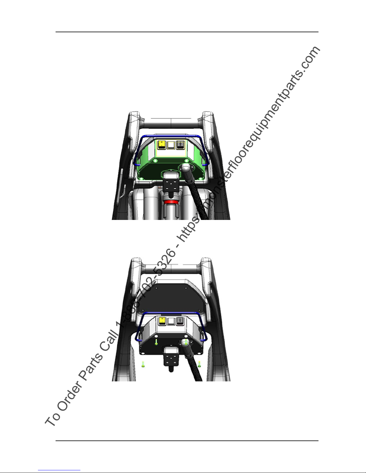
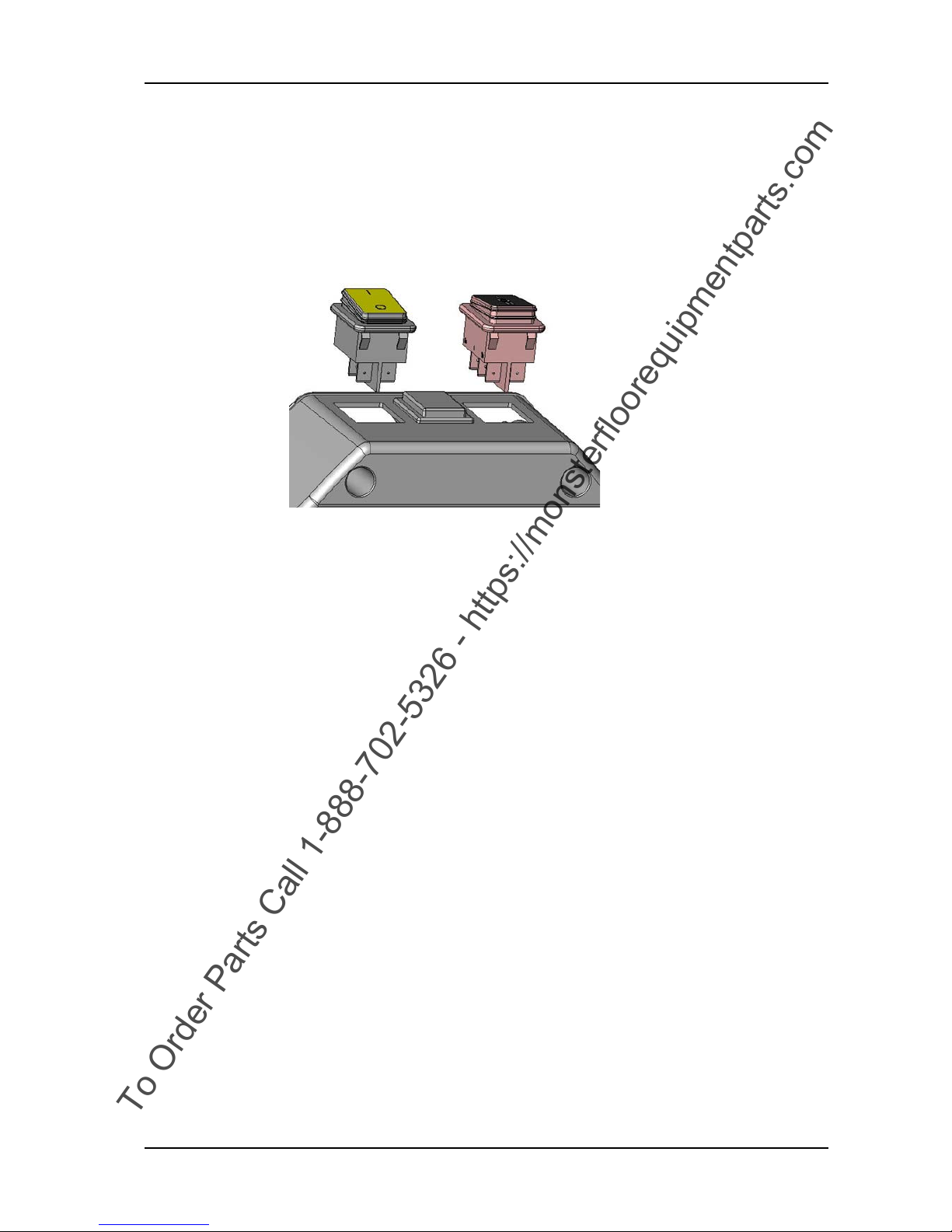
6.2.1 Removing of rockingswitch
Picture 2: Rockingswitch
• Remove the housing according to chapter REMOVING OF
HOUSING in the section mechanical.
• Disconnect the electrical connections of the rockingswitch (01/
101, 102).
• Push out the rockingswitch from the inner side of the housing
(01/104).
To Order Parts Call 1-888-702-5326 - https://monsterfloorequipmentparts.com
GTS Technical Manual
14. March 2014 Edition: V1.00/2014 6-3
Copyright © 2014, Diversey Care
06.14.19 dashboard - 30_V1.00.fm
6.2 Main cord & cable inlet inbox
6.2.2 Mounting of rockingswitch
Picture 3: Rockingswitch
• Push the rockingswitch into the housing from the outer side.
Remarks
Make sure that the rockingswitch is correctly positioned and clicks
into the housing.
• Connect the electrical connections to the rockingswitch.
• Mount the housing according to chapter MOUNTING OF
HOUSING in the section mechanical.
To Order Parts Call 1-888-702-5326 - https://monsterfloorequipmentparts.com

GTS Technical Manual
14. March 2014 Edition: V1.00/2014 6-4
Copyright © 2014, Diversey Care
06.14.40 dashboard - connections - 30_V1.00.fm
6.2 Main cord & cable inlet inbox
6.2.3 Rockingswitch connections
Picture 4: Dashboard connections
To Order Parts Call 1-888-702-5326 - https://monsterfloorequipmentparts.com

GTS Technical Manual
14. March 2014 Edition: V1.00/2014 6-5
Copyright © 2014, Diversey Care
06.14.40 dashboard - connections - 30_V1.00.fm
Pos. Plug Description [plug] Pin Description [pin]
1 HS Main rockingswitch 1 (OUT) OUT main phase
=> Pump
=> Contactor K1
=> Magnetic valve DS1/DS2/DS3
2 HS Main rockingswitch 2 (OUT) OUT main neutral
=> Vacuum motor rockingswitch, further to
contactor K1
=> Pump
3 HS Main rockingswitch 1a (IN) IN main phase
=> contactor K1/K2
4 HS Main rockingswitch 2a (IN) IN main neutral
=> contactor K1/K2
5 BS Vacuum motor/pump/dosing rockingswitch 1b (OUT) Magnetic valve
=> DS1
=> DS3
6 BS Vacuum motor/pump/dosing rockingswitch 2b (OUT) (Not connected)
7 BS Vacuum motor/pump/dosing rockingswitch 1 (IN) Microswitch brush motor
=> contactor K2
8 BS Vacuum motor/pump/dosing rockingswitch 2 (OUT) Microswitch brush motor
9 BS Vacuum motor/pump/dosing rockingswitch 1a (OUT) Magnetic valve
=> DS2
10 BS Vacuum motor/pump/dosing rockingswitch 2a (OUT) Contactor K1
=> Vacuum motor
Table 1: Rockingswitch connector description
To Order Parts Call 1-888-702-5326 - https://monsterfloorequipmentparts.com

GTS Technical Manual
14. March 2014 Edition: V1.00/2014 6-6
Copyright © 2014, Diversey Care
06.16.13 contactor - 30_45_V1.00.fm
6.3 Contactor
6.3.1 Removing of contactor
Picture 5: Contactor
• Open fresh water tank according to chapter REMOVING OF FRESH
WATER TANK ASSEMBLY.
Ensure that no water is in the fresh water system before you
disconnect the hoses.
• Disconnect the plugs from the contactor (30:03/104, 45:04/
104) or (30:04/120, 45:05/120).
• Remove the two screws (30:03/103, 45:04/103) or (30:04/101,
45:05/101) from the contactor.
• Remove the contactor.
To Order Parts Call 1-888-702-5326 - https://monsterfloorequipmentparts.com

GTS Technical Manual
14. March 2014 Edition: V1.00/2014 6-7
Copyright © 2014, Diversey Care
06.16.13 contactor - 30_45_V1.00.fm
6.3 Contactor
6.3.2 Mounting of contactor
Picture 6: Contactor
• Position the contactor on the chassis.
• Mount the two screws.
• Connect the plugs onto the contactors.
Connect the plugs according to the number coding.
• Close fresh water tank according to chapter MOUNTING OF
FRESH WATER TANK ASSEMBLY.
To Order Parts Call 1-888-702-5326 - https://monsterfloorequipmentparts.com

GTS Technical Manual
14. March 2014 Edition: V1.00/2014 6-8
Copyright © 2014, Diversey Care
06.16.22 contactor connections - 30_45_V1.00.fm
6.3 Contactor
6.3.3 Contactor connections K1/K2
Picture 7: Contactor connections
To Order Parts Call 1-888-702-5326 - https://monsterfloorequipmentparts.com

GTS Technical Manual
14. March 2014 Edition: V1.00/2014 6-9
Copyright © 2014, Diversey Care
06.16.22 contactor connections - 30_45_V 1.00.fm
6.3.3.1 Contactor connections K1
Pos. Plug Description [plug] Pin Description [pin]
1 0 Contactor - Coil 0 => Contactor - Coil (K2)
=> Main switch (HS)
2 1 Contactor - Coil 1 Dosing switch
32Contactor 2Vacuum motor
4 4 Contactor 4 => Main switch (HS)
=> Contactor (K2)
56Contactor 6Vacuum motor
68Contactor 8=> Neutral
=> Contactor (K2)
Table 2: Contactor connections description K1
To Order Parts Call 1-888-702-5326 - https://monsterfloorequipmentparts.com

GTS Technical Manual
14. March 2014 Edition: V1.00/2014 6-10
Copyright © 2014, Diversey Care
06.16.22 contactor connections - 30_45_V 1.00.fm
6.3.3.2 Contactor connections K2
Table 3: Contactor connections description K2
Pos. Plug Description [plug] Pin Description [pin]
1 0 Contactor - Coil 0 => Contactor - Coil (K1)
=> Main switch (HS)
2 1 Contactor - Coil 1 Dosing switch
32Contactor 2Brush motor
4 4 Contactor 4 => Main switch (HS)
=> Contactor (K1)
56Contactor 6Brush motor
68Contactor 8=> Neutral
=> Contactor (K1)
To Order Parts Call 1-888-702-5326 - https://monsterfloorequipmentparts.com

GTS Technical Manual
14. March 2014 Edition: V1.00/2014 6-11
Copyright © 2014, Diversey Care
06.28.20 schematics - electrical schematics - 30_45_V1.00.fm
6.4 Electrical schematics
6.4.1 Electrical schematics
Picture 8: Electrical schematics
To Order Parts Call 1-888-702-5326 - https://monsterfloorequipmentparts.com

14. March 2014 Edition: V1.00/2014
Copyright © 2014, Diversey Care
Technical Manual
7 Additional information
To Order Parts Call 1-888-702-5326 - https://monsterfloorequipmentparts.com

GTS Technical Manual
14. March 2014 Edition: V1.00/2014 7-1
Copyright © 2014, Diversey Care
08.1 procarpet 30 - additional information_V1.00.fm
7 Additional information
7.1 Available GTS Newsletter/Instructions
To find the up to date available GTS Newsletters and instructions refer to e-spares.
Newsletter Date of issue Machine Subassembly Topic/Modification Serial
number
Table 1: Newsletters/Instructions
To Order Parts Call 1-888-702-5326 - https://monsterfloorequipmentparts.com

14. March 2014 Edition: V1.00/2014
Copyright © 2014, Diversey Care
Technical Manual
8 Revision
To Order Parts Call 1-888-702-5326 - https://monsterfloorequipmentparts.com

GTS Technical Manual
14. March 2014 Edition: V1.00/2014 8-1
Copyright © 2014, Diversey Care
09.1 procarpet 30 - revision_V1.00.fm
8 Revision
Date Chapter Content Description Revision
Table 1: Revision
To Order Parts Call 1-888-702-5326 - https://monsterfloorequipmentparts.com

14. March 2014 Edition: V1.00/2014
Copyright © 2014, Diversey Care
Technical Manual
9 Appendix
To Order Parts Call 1-888-702-5326 - https://monsterfloorequipmentparts.com

GTS Technical Manual
tecnical manual procarpet 30_V1.00MIX.fm
14. March 2014 Edition: V1.00/2014
Copyright © 2014, Diversey Care
Glossar
A
Accessories 4-4
Additional information 7-1
Adjusting of brush height 5-18
B
Brush & Motor 5-12, 5-13, 5-14, 5-15,
5-16, 5-17, 5-18
Brush motor 5-14, 5-15
Brush motor belt 5-12, 5-13
Brush pulley 5-16, 5-17
Brush system 4-4
Bypass valve 5-32, 5-33
C
Consumable supplies 3-1
Contactor 6-6, 6-7, 6-8
Contactor connections 6-8
D
Dashboard connections 6-4
Dimensions and weights 4-3
Direction description 3-1
E
Electrical schematics 6-11
Elementary 2-1
ESD 2-1
F
Filter 5-30, 5-31
Foreword 1-1
Fresh water tank assembly 5-8, 5-10
G
General 3-1
H
Handle 5-1, 5-3, 5-5, 5-6, 5-7
Health & Safety 2-1
Housing 5-1, 5-2
M
Machine profile 4-2
Machine range 4-1
Magnetic valve & water outlet 5-28, 529, 5-30, 5-31, 5-32, 5-34, 5-35
Magnetic valve, electrical parts 5-33
Main cord & cable inlet inbox 6-2, 6-3,
6-4
Material 3-2
Microswitch 5-3, 5-5
Motor circuit 6-1
N
Newsletter/Instructions 7-1
P
Part reference 3-1
Power source 3-1
Pump 5-28, 5-29
R
Required material 3-2
Revision 8-1
Rockingswitch 6-2, 6-3, 6-4
Rockingswitch connections 6-4
S
Shackle 5-21, 5-22
Static discharge 2-2
Suction power 4-4
Summary 1-2
Switching bow 5-6, 5-7
System architecture 6-1
T
Tank cover and tank 5-8, 5-10
Technical data 4-1, 4-2
Technical information 4-2
Technical Manual 1-1
Technical Training 1-1
Tools 3-2
V
Vacuum motor 5-19, 5-20, 5-23, 5-24,
5-25, 5-27
To Order Parts Call 1-888-702-5326 - https://monsterfloorequipmentparts.com

GTS Technical Manual
tecnical manual procarpet 30_V1.00MIX.fm
14. March 2014 Edition: V1.00/2014
Copyright © 2014, Diversey Care
Vacuum unit 5-19, 5-21, 5-23, 5-25 Valve unit 5-34, 5-35
To Order Parts Call 1-888-702-5326 - https://monsterfloorequipmentparts.com

14. March 2014 Edition: V1.00/2014
Copyright © 2014, Diversey Care
Technical Manual
10 Notes
To Order Parts Call 1-888-702-5326 - https://monsterfloorequipmentparts.com
 Loading...