

Taski swingobot 1650 CE, swingobot 1650 CE UV, duobot 1850 CE, duobot 1850 CE UV User Manual
www.intellibotrobotics.com
Rev. B:
01/09/17
TASKI SWINGOBOT 1650 CE
TASKI SWINGOBOT 1650 CE UV
USER MANUAL

1
Original Language Version (ENGLISH)
Attention:
Read and understand these instructions
before use.
This manual includes important information about the safe
use of this machine. Keep these instructions in an easily
accessible location for reference.
1. System Overview
The TASKI Intellibot SWINGOBOT 1650 and TASKI Intellibot
SWINGOBOT 1650 UV are robotic oor scrubbing machines
intended for commercial use. The following is an overview of
the machine features.
INTELLIGENT FEATURES
Main Computer Monitors all functions; commands robot
to perform stored cleaning routes
Drive
Subsystem
Monitors and controls the robot’s
movement and position
Controls Manual and autonomous
Navigation 16 sensors provide a complete,
360-degree view around robot
Front Touch
Shield
Full width, ABS, touch-sensitive shield
provides immediate braking
Rear Touch
Shield
Full width, ABS, touch-sensitive shield
provides immediate braking
Security User-specic password protection to
prevent unauthorized use
Safety Systems Sonar obstacle detection, infrared oor
sensors, touch shields, emergency
stop button
SOLUTION RECYCLING SYSTEM
Solution Feed Computer-controlled, adjustable ow
rate to center of each brush
Solution Tank Integral 14-gallon (53-liter) molded
high-density polyethylene with easyaccess lid
Recycling
System
Four-stage automatic recycling system
lters to 10 micron standard, 1 micron
optional for SWINGOBOT 1650 UV
BRUSHES AND SQUEEGEE
Pads Two counter-rotating 15” drivers and
pads
Brush Head Pads are changeable without removing
head from machine
Scrubbing
Width
29" (73.66 cm)
Scrubbing
Pressure
100 lbs. (45.36 kg)
Squeegee 32" (81.28 cm), parabolic, self-
centering swing style with plastic end
rollers and quick change, four-edge,
reversible rubber blade
SECTIONS
1. System Overview ............................................. 1
2. Customer Assistance ...................................... 2
3. Supplies, Parts and Accessories ....................2
4. Intended Use .................................................... 2
5. Personnel Responsibilities ............................. 2
6. General Safety Awareness .............................. 3
7. System Safety Awareness ............................... 4
8. Risk ................................................................... 6
9. Preventing Unsafe Situations ......................... 7
10. Healthcare/UV User and Service Personnel
Warnings ........................................................... 8
11. Machine Overview ............................................ 8
12. Theory of Operation: .....................................10
13. Safety Devices ................................................ 13
14. Safety Circuit Wiring ...................................... 15
15. Batteries .......................................................... 16
16. Charging ......................................................... 17
17. Language Setup ............................................. 18
18. Administrative Setup ..................................... 18
19. System Preferences ....................................... 20
20. Commissioning After Storage ...................... 20
21. Weekly Safety Device Check......................... 20
22. Daily Startup Procedure ................................ 23
23. Review of Work Area ..................................... 24
24. Manual Drive ................................................... 25
25. Manual Cleaning ............................................25
26. Hands Free Cleaning .....................................25
27. Daily Shutdown Procedure ...........................28
28. Maintenance ................................................... 30
29. Replacement Components ............................ 31
30. Storage ............................................................ 31
31. Troubleshooting ............................................. 31
32. Diagnostics ..................................................... 32
33. Sonar Diagnostic ...........................................32
34. Touch Shield Diagnostic ...............................32
35. Floor Sensor Diagnostic ...............................33
36. Gyro Diagnostic .............................................33
37. Gyro Calibration ............................................. 33
38. Network Diagnostic .......................................34
39. WiFi Diagnostic .............................................. 34
40. Memory Diagnostic ........................................ 34
41. Outputs Diagnostic ........................................ 35
42. Flow Diagnostic .............................................35
43. Drive Motor Diagnostic .................................. 35
44. Technical Data ................................................ 36
45. Revisions ........................................................ 37

2
DRIVE SYSTEM
Drive Motors Two 24 VDC precision motors, built-in
encoders, traction water displacement
tread
Vacuum Motor Single 67 CFM vacuum
PRODUCTION
Cleaning Rate Approximately 10,000 sq ft (approx.
929 sq m) per hour (avg.)
BATTERY SYSTEM
Battery Sealed gel cell or AGM deep cycle,
180 AH, 24 VDC output
Run Time Approximately four hours
Optional
Exchange Kit
Run time can be doubled with battery
exchange kit
Charger Unit 20 amp, 24 VDC output, 115 VAC input
with automatic shutoff
Charge Time: Approximate full charge time minimum
12 hours.
CONSTRUCTION
Frame Powder-coated 5052 aluminum and
stainless steel
Exterior High-density, molded, seamless
polyethylene
Machine Length 48" (121.92 cm)
Machine Width 32" (81.28 cm)
Machine Height 43" (109.22 cm)
Machine Weight 720 lbs. (326.6 kg)
ENVIRONMENT
Temperature 59° to 86° F (15° to 30° C) operation,
-22° to 140° F (-30° to 60° C) storage
Humidity 20% to 75% relative humidity
1.1. Statement of Airborne Noise Emission
This machine does not exceed 75 dB(A) during operation or
maintenance.
1.2. Statement of Compliance
This product complies with all applicable European Union
Directives and Harmonized standards as of the date of
manufacture. See product ratings label for specic model
and serial number information.
Applicable EU Directives
2006/42/EC 2004/108/EC 1995/5/EC
1.3. Applicable EU Harmonized Standards
EN 60204-1 EN 60335-1 EN 12100
EN 60335-1
EN 60335-2-72 (manual mode operation)
EN 12100 EN 13857 EN 349
EN 14121 EN 55014-1 EN 55014-2
2. Customer Assistance
For questions relating to the operation, maintenance, or
service of this robotic oor scrubber system, please contact:
2.1. Equipment Manufacturer:
Diversey Care Intellibot
12820 West Creek Parkway
Suite B
Richmond, Virginia 23238 U.S.A.
Phone (US): 01.888.837.0002
Email: ir-service@sealedair.com
Web: www.intellibotrobotics.com
2.2. European Union Representative:
Diversey Europe Operations B.V.
Maarssenbroeksedijk 2
3542 DN Utrecht, Netherlands
Email: customerservice.nl@sealedair.com
Phone (EU): 31.030.247.6885
3. Supplies, Parts and Accessories
For optimal machine performance, only Diversey Care
cleaning solutions approved for use with this machine
should be used. To maintain performance, and safety of the
machine, personnel, and property, only TASKI Intellibot parts
and accessories should be used to maintain this robotic oor
scrubber system.
Please contact Customer Assistance for any questions
regarding the use, maintenance, or service of this robotic
oor scrubbing system
4. Intended Use
This robotic oor scrubbing system is an industrial oor
scrubbing machine intended for interior use in commercial
buildings. The machine should only be used for the wet
cleaning of hard commercial oor surfaces.
This machine must be attended by an operator at all times
during use. The operator is responsible for the safe operation
of this machine and must follow the operating and safety
instructions provided in this manual.
5. Personnel Responsibilities
The following Identies personnel requirements for the safe
use of this equipment.
5.1. Manager
It is the manager’s responsibility to ensure that operator(s)
and maintenance personnel are properly trained in the
use and maintenance of this robotic oor scrubber system.
Managers must ensure that operator and maintenance
personnel are provided with the appropriate supplies and
equipment needed to safely operate the machine.

3
5.2. Operator
A operator refers to a user of this equipment who is properly
trained in the use, maintenance, and troubleshooting of this
robotic oor scrubber system. The operator is responsible
for ensuring that maintenance is performed only by trained
maintenance personnel.
5.3. Maintenance Personnel
Maintenance personnel must be properly trained to maintain
this robotic oor cleaning equipment. Maintenance includes
replacement of consumables such as water, detergent,
lters, scrubbing pads, and scheduled cleaning of the
machine.
5.4. Service Technician
A service technician refers to a eld engineer who is properly
trained in the use, maintenance, troubleshooting, and service
of this robotic oor scrubber system. A service technician
must have factory service training.
The service technician is responsible for all repairs,
upgrades, and accessory installations requested by
the customer or mandated by TASKI Intellibot. Service
technicians are equipped with proper tools and parts for the
installation, maintenance, and service of this robotic oor
scrubber system.
6. General Safety Awareness
The following section includes important information required
for safe operation of this robotic oor scrubber system.
6.1. User Manual Safety Symbols
The following symbols are used to identify important safety
information:
Warning:
Failure to follow this information could result
in serious harm to people and/or property.
Caution:
Failure to follow this information could result
in damage to the machine and/or property.
Note:
Failure to follow this information could result
in malfunction or damage to the machine.
6.2. General Safety Instructions
The following symbols are used to identify important safety
information:
This machine may only be used by a trained
operator that is physically and mentally
capable of maintaining control and safety of
the machine. Physical or mental impairment
of the user may result in serious injury to
people, property, and/or the machine.
In case of damage to safety relevant
components such as the Emergency Stop
switch, safety interlock, safety touch shields,
front door, batter, etc., the machine must be
stopped immediately. Repair or replacement
of the damaged component by a qualied
service.
Unauthorized use or modication of this
machine may result in unsafe operating
conditions, personal injury, property damage
or machine malfunction. Any unauthorized
modication or use contrary to the intended
purpose will result in voiding the machine
warranty, CE marking, and applicable safety
marks.
Do not use this machine around any
explosive or ammable materials or in
any areas where vapors from ammable
materials such as solvents, fuel, oil or dust
could ignite.
Do not use this machine to vacuum
ammable, toxic, caustic, or irritating
substances. The machine is not designed
for this use and serious injury to persons
and damage to property and the machine
may result.
Do not use this machine in areas with
high electromagnetic elds (EMF). This
machine uses electronics susceptible
to electromagnetic elds. Use of this
equipment in high EMF areas may result in
unintended and uncontrolled operation.
Stairways and doorways must be blocked
when the scrubber is used in robotic mode.
Failure to block a stairway could result in the
machine tumbling down the stairs, resulting
in serious property damage, machine
damage and injury.
Operators must take note of the
surrounding area and be ready to stop the
machine in case a hazardous situation. The
machine must be stopped if any potentially
hazardous situation arises, such as children
entering the cleaning area, objects falling
in the machine path, stairway blocks are
moved, etc. Children should never be
allowed to play in or around the cleaning
area while the robotic oor scrubber system
is in operation.
Never use the robotic oor scrubber system
to transport people or materials. Serious
injury and property damage may result.
4
Regularly inspect the battery charger,
mains cord, and machine charging cable
for damage and replace the cord or charger
immediately if any damage is found. Frayed
or damaged charging components could
lead to shock or re.
Caution:
This machine is not intended for the
application of wax, polishing, carpet
cleaning, or the dry vacuuming of dust.
Cleaning of wood or laminate oors is not
recommended. The owner assumes all
risk for use on surfaces not designed to
be cleaned with commercial scrubbing
equipment.
Caution:
This machine is only intended for indoor
use in dry areas. Do not use or store this
machines outdoors or in damp conditions.
Caution:
This machine uses detergent as part
of the scrubbing system. Please read,
understand, and follow all manufacturer’s
instructions for the safe and effective
use of the detergent. Failure to follow the
manufacturer’s recommendations, including
the use of safety equipment, such as
gloves and safety glasses, could result in
hazards to people, property, and/or machine
malfunction.
Caution:
The machine may only be operated with
the top cover closed. Foam or liquid leaking
from the sides or top of the machine
indicates a malfunction. The machine must
be stopped immediately and the malfunction
identied and corrected before the machine
is returned to operation.
Caution:
Always use the parking brake when the
machine is unattended.
Caution:
The machine is intended for use on at
surfaces. Operating the machine on a grade
exceeding 2% may result in unintended
operation. Do not store or transport the
system on a grade exceeding 8% or the
machine may tip over resulting in injury and/
or damage to the machine.
7. System Safety Awareness
Safety and informational labeling is included on the machine
to remind the operator of specic hazards encountered while
operating and maintaining the robotic oor scrubber system.
The following is a denition of the machine safety labels.
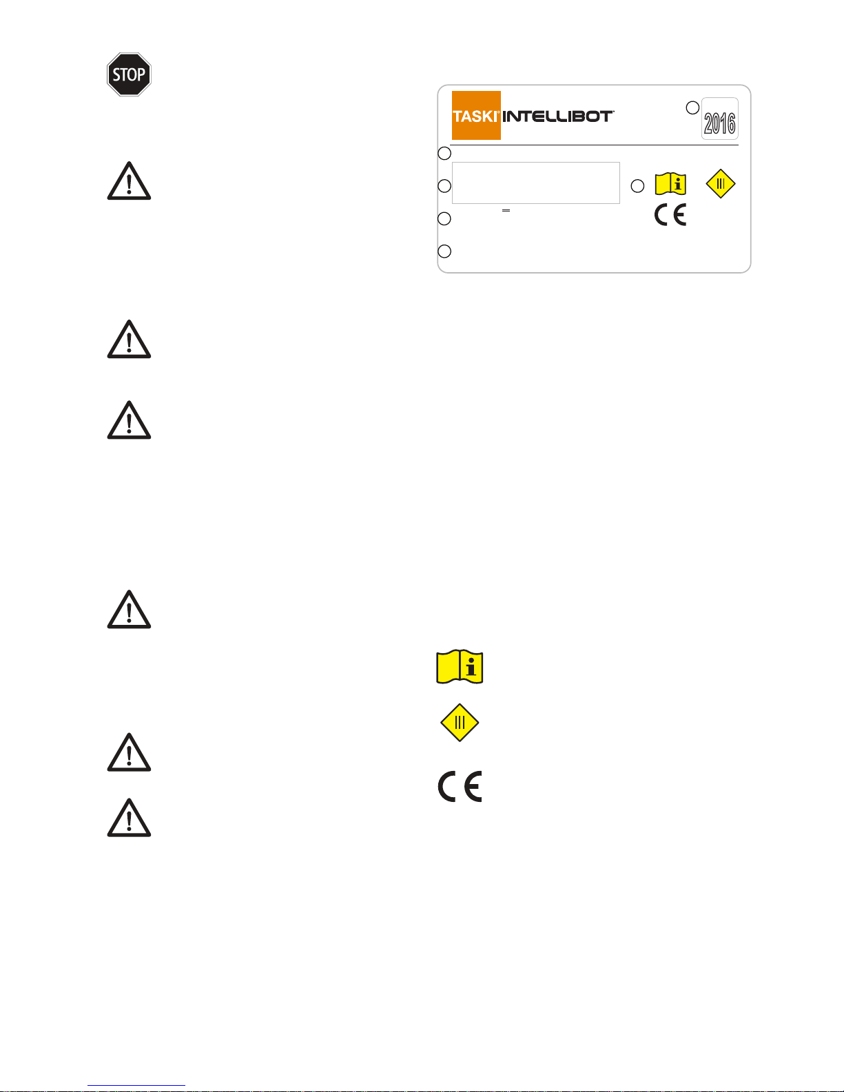
7.1. Ratings Label
Example machine ratings label:
SWINGOBot 1650-UV
Robotic Floor Scrubber System
Input: 24V , 53.2A, 1280W
Weight:
208kg without battery pack
342kg with battery pack
IPX4
September
11609-1105-0001
Diversey Europe Operations B.V.
Maarssenbroeksedijk 2
3542 DN Utrecht, Netherlands
www.sealedair.com
This equipment is manufactured by Diversey Inc. (US) and
is covered under U.S. Patent #'s 6,580,246, 6,667,592,
9,028,617. Other patents pending. Commercial Use Only.
1
2
3
4
5
7
Figure: 1
The ratings label contains the following information:
1 Model: The model name and description of the
machine.
2 Serial Number: The unique serial number of
this machine. The serial number of the machine
should always be noted when customer
assistance is needed.
3 Input Ratings: The machine is powered by 24 Volt
DC batteries. For more information on appropriate
batteries, see the Battery Safety section of this
manual.
Weight: The weight of the machine is important
for operation and shipping. Always ensure
stability of the operating environment. Always
ensure shipping containers and securement is
appropriate for a machine of this weight.
4 Manufacturer: Information regarding the
manufacturer and intellectual properties.
5 Informational Labeling:
Refer to this manual for important
information regarding operation and safety
of this machine.
This machine is powered from a safety
extra-low voltage power source and
is considered a Class III device when
operating in a dry environment.
This machine complies with all relevant
safety and health requirements of the
applicable EU Directive(s). See the
Declaration of Conformity for the specic
Directives and standards applicable to this
machine.
IPX4
This machine was designed and tested to
meet the standards for a level 4 protection
against liquid ingress.
6 European Union Representative: The
manufacturer’s representative for the European
Union.
7 Date of Manufacture: The date of manufacture of
this machine.
5
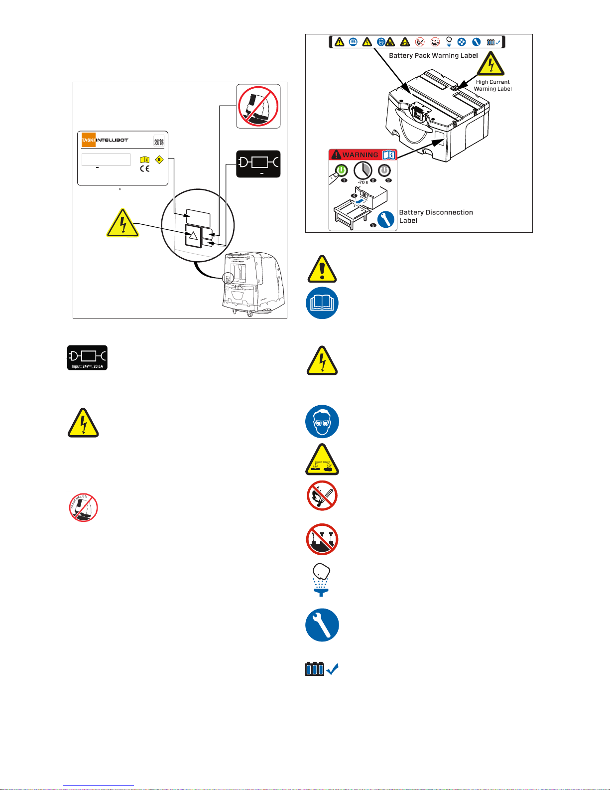
7.2. System Warning Labels
The following labels are used to warn and remind the
operator, maintenance, and service personnel of specic
hazards when using the machine:
High Voltage
Warning Label
Input: 24V , 20.0A
Charger Input/Warning
Identification Label
Maximum 8% Grade
Warning Label
G
R
A
D
E
M
A
X
8
%
SwingoBot Rating Label
SWINGOBot 1650-UV
Robotic Floor Scrubber System
Input: 24V , 53.2A, 1280W
Weight:
208kg without battery pack
342kg with battery pack
IPX4
September
11608-1105-0001
Diversey Europe Operations B.V.
Maarssenbroeksedijk 2
3542 DN Utrecht, Netherlands
www.sealedair.com
This equipment is manufactured by Diversey Inc. (US) and
is covered under U.S. Patent #'s 6,580,246, 6,667,592,
9,028,617. Other patents pending. Commercial Use Only.
Figure: 2
This symbol identies the location of the
machine battery charging port. Only gel cell
battery chargers should be used with this
machine. Do not exceed the maximum 20
Amp charging current.
Hazardous current is present at the
machine charging port. Never use any
metallic object, such as a screw driver, to
open the charging ap or pry the charging
connector. Never place any object in the
charging port other than the charging
connector.
The maximum stable angle for storage
and transport. Do not store or transport the
system on a grade exceeding 8% or the
machine may tip over resulting in injury and/
or damage.
7.3. Battery Warning Labels
The following labels are used to warn and remind the
operator, maintenance, and service personnel of specic
hazards associated with the batteries used in this robotic
oor scrubber system:
Figure: 3
This is the attention symbol, warning of
hazards to persons and property.
This symbol refers the operator,
maintenance, or service personnel to
the appropriate manual for important
information.
Hazardous current is present at the battery
charging port and the battery terminals at
all times. Never store anything on top of the
batteries. Always use caution when using
any metallic object near the batteries.
Protective eye-wear must be worn when
working on the batteries.
The batteries contain caustic acid that can
cause severe burn or blindness.
The batteries emit ammable/explosive gas.
Do not allow sparks, re or ame near the
batteries. Never smoke near the batteries.
Do not remove the battery vent valve.
Caustic acid is present inside the batteries.
If exposed to acid, immediately ush with
water and consult medical attention.
Batteries should only be serviced by a
trained service technician.
Use only approved gel cell or AGM batteries
in this machine.
7.4. Battery Charger Labeling
When a battery charger is used on a battery cart, the charger
should be equipped with a cover to prevent accidental
spillage of liquid onto the unit.

6
The cover has the following safety labels:
High Voltage
Warning Label
Charger IP
Rating Label
Figure: 4
Hazardous voltage is present when the
charger is plugged into the mains.
Hazardous currents are also present at all
times when the charger is connected to the
battery.
Cover was designed to meet the standards
for a level 4 protection against liquid ingress
into the battery charger.
The battery shutdown warning label instructs the user to
shut down the machine and wait for the standby button
illumination to turn off.
Figure: 5
Before Removing Batteries, hold ~ Standby button,
listen for 3 Beeps, which is the computer acknowledging your
button push. Computer will turn off 24V circuits & start saving
data.
Caution, for the next 30-90 seconds the computer
saves data, wait for button light to go "Off" or you will lose the
data. If light is still on after 120 Seconds, to prevent damage
or injury hit e-stop to assure 24V power is disconnected from
battery before breaking connection by pulling on battery
handle.
Button goes dark; computer has shut down all power.
All power is off; no trickle power is leaking from the battery to
any circuit.
8. Risk
Although all reasonable precautions have been taken to
ensure the safety of this machine, there are certain foreseen
risks that the manager, operator, maintenance and service
personnel must address:
8.1. General Risk: Care should be
taken to prevent the following:
Inadequate Training: Operators,
maintenance, and service personnel must
be properly trained. It is the manager’s
responsibility to ensure the machine is not
accessible to inadequately trained persons.
Lack of Supervision: The robotic oor
scrubbing system must be supervised at all
times. The operator must be able to react
to situations that may endanger people or
property.
Lack of Stairway Obstruction: When
using the robotic oor scrubbing system
in autonomous mode, all stairways and
doorways must be blocked to prevent the
unit from proceeding on an unintended
path. Stairways must be blocked to prevent
the unit from tumbling down the stairs and
potentially causing serious damage or injury.
Unt Components: Only components
authorized by TASKI Intellibot may be tted
to this machine. Use of unt components
may result in serious damage and injury.
Bacterial Growth: Proper cleaning during
maintenance and service is required to
prevent the growth of bacteria in the robotic
oor scrubber system.
Transportation Incidents: The machine can
tip over if subjected to a grade in excess of
8%, resulting in serious damage and injury.
When transporting the unit by vehicle, it
must be strapped to a supporting structure
capable of securing the full specied weight.
Operating While Damaged: The machine
must never be operated while damaged.
Damage to the machine may result in
unsafe conditions for people and property.
A damaged machine must be serviced by a
trained service technician before returning
to use.
Operating Without Safety Measures: The
machine is designed with specic safety
measures to protect people and property.
Damage or defeat of these mechanisms
may result in serious injury.
8.2. Operational Risk: Care should
be taken to prevent the following while
operating the machine:
Entrapment: Avoid situations that could trap
an operator between the machine and an
object.
Inadvertent Motion: Be aware that gripping
the handle can initiate machine motion. Do
not grip the handle unless intending to move
the machine in manual mode.
7
Operating on an Incline: The machine
can tip over causing damage and injury if
operated on an incline.
Parking on Incline: Always apply the parking
break to prevent the machine from moving.
Setting Wrong Direction or Speed: Be
aware of the direction and speed set in
manual mode. Setting the incorrect speed
or direction could entrap the operator
between the machine and an object.
Unauthorized Use: Never leave the
machine unattended.
Brush or Squeegee Entanglement: Use
care when lowering the brush or squeegee
assemblies. Always ensure adequate
clearance from people and objects to
prevent entanglement.
Safety System Malfunction: Safety systems
need to be checked for proper operation
before operating the machine.
Insufcient Braking Distance: Care must
be taken to ensure an appropriate braking
distance is maintained at all speeds and
slopes.
8.3. Residual Risk: The operator should
be aware of the following residual risks
when using the machine:
Rotating Mechanism Pinch Hazard:
The robotic oor scrubber system includes
motors and scrubbing brushes with
pads. A pinch hazard exists when these
mechanisms are raised and lowered. Do
not allow access to these areas while the
machine is turned on.
Rotating Mechanism Entanglement
Hazard: The rotating mechanisms can
entangle clothing or body parts. Do not
allow access to these areas while the
machine is turned on.
Squeegee Pinch Hazard: The squeegee
bar support may cause a pinch hazard
when raised. Do not allow access to the
squeegee when raising or lowering the
mechanism.
Squeegee Grab/Hook Hazard: It is
possible for the squeegee to grab or hook
objects projecting from the oor or located
in the plane of the squeegee. The operator
must be aware of the operating environment
and ensure that the machine is not used
around objects or people that could be
grabbed by the squeegee mechanism.
Machine Impact Hazard: When in
autonomous mode, the robotic oor
scrubber system uses sonar for locating
objects in its path. The sonar system cannot
be relied on for safety. It is possible for the
sonar to malfunction or for personnel to be
located in gaps between sonar sensors,
posing an impact hazard. The operator
must never allow personnel to located in the
autonomous operating area.
Uncontrolled Motion (E-Stop): The
machine may pose an impact hazard if the
Emergency Stop switched is pressed while
on an incline. Always engage the parking
brake when the machine is unattended.
Entrapment Hazard: It is possible for
an operator to trap themselves between
the machine and an object . Care should
be taken to avoid tight spaces. In case of
emergency, let go of the handle and press
the Emergency Stop button.
Warning: Never operate the unit in the
presence of unsupervised young children.
Their curiosity and reduced mass puts them
in danger of severe injury.
9. Preventing Unsafe Situations
The following additional information should be considered
to prevent unsafe situations when using the robotic oor
scrubber system.
9.1. Protective Equipment
The following protective equipment is recommended when
dealing with detergents, wash water, waste water, or spills:
Protective eye-wear with side shields.
Protective rubber or neoprene gloves and
apron.
Non-slip footwear.
9.2. Operating the Machine
The machine uses water and detergent
during the cleaning process. The oor
immediately behind the machine may
be wet and slippery. Non-slip footwear
is recommended to prevent falls while
operating the machine.
Operators should always wear clothing
appropriate for working with a commercial
scrubber. Do not wear loose or torn
clothing that may get entangled on or in the
machine.
8
9.3. Spilled Clean Water
For water spills, wipe the machine with
paper towels and mop the oor as required.
9.4. Spilled Waste Water
Waste water will contain detergents and dirt
from the oor. Protective eye-wear, gloves,
and an apron are recommended.
Rinse the equipment with clean water as
required and wipe with paper towels.
Rinse and mop the oor with clean water as
required.
9.5. Spilled Detergent
Always follow the manufacturer’s
recommendations for handling the
detergent. Detergents can be caustic,
protective eye-wear, gloves, and an apron
are recommended.
Rinse the equipment with clean water as
required and wipe with paper towels.
Rinse and mop the oor with clean water as
required.
9.6. Battery Acid
Consult the battery manufacturer’s
recommendations for cleanup. For help
with batteries supplied by TASKI Intellibot,
please contact Customer Assistance.
10. Healthcare/UV User and Service Personnel
Warnings
Personnel should be made aware of the following hazards:
10.1. UV Hazard
WARNING:
The UV light given off by this unit can cause
serious burns to unprotected eyes and skin.
Never look directly at an illuminated UV
lamp. Never operate the unit with the lamp
outside of the UV chamber. Never operate
the unit without the rubber boot in place.
10.2. Mercury
UV lamps contain Mercury, a heavy metal.
Lamps should be recycled, not disposed of
in a landll. Recyclers accepting uorescent
lamps will typically also accept UV lamps.
The Mercury from a broken UV lamp must
be recovered and recycled appropriately.
10.3. Puncture and Cutting Hazard
The UV lamp and quartz sleeve are fragile.
If they break, pieces will be very sharp and
the fragments must be handled only with
protective gloves.
10.4. High Voltages
The UV ballast uses and produces
hazardous voltages. Caution should be
taken when servicing components near the
ballast or UV reactor.
The UV ballast is designed for a dry
environment only. If the ballast is exposed
to water, remove power immediately. Never
operate a ballast that has been exposed to
water.
Hazardous voltages exist in the UV reactor
vessel. Never operate a leaking UV unit.
Remove power before inspecting the unit
for damage.
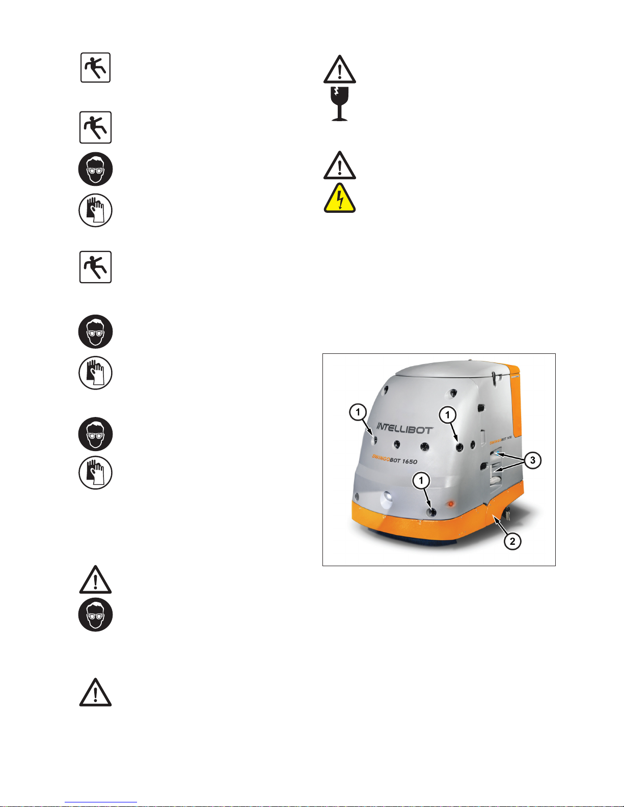
11. Machine Overview
The following are basic components of the robotic oor
scrubbing machine:
Figure: 6
1 Sonar Horns
2 Safety Touch Shield
3 Drain Valve and Drain Hose
9
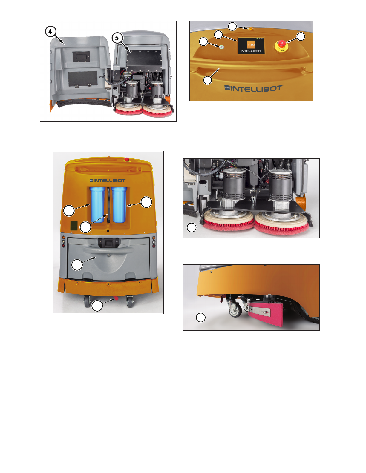
Figure: 7
4 Front Access Door
5 Electronics Box
6
8
9
6
7
Figure: 8
6 Filters
7 Filter Wrench
8 Battery Pack
9 Parking Brake
14
11
12
13
10
Figure: 9
10 Emergency Stop Button
11 User Interface
12 Standby Button
13 Touch Control Handlebar
14 Warning Lamp
15
Figure: 10
15 Scrubber Head
16
Figure: 11
16 Squeegee Assembly

10
11.1. SWINGOBOT 1650 CE UV ONLY
17
18
Figure: 12
17 UV Sterilizer Power Supply
18 UV Sterilizer Reactor
12. Theory of Operation:
The TASKI Intellibot SWINGOBOT 1650 CE and CE UV
machines are commercial wet oor scrubbing systems
capable of manual and autonomous robotic operation.
Figure: 13
The system utilizes a 14 gallon (53 liter) tank for storing and
recycling cleaning solution that is applied to the scrubber
head for effective cleaning.
The scrubber head is comprised of two independent motors
with brushes and 15-inch pads for wet scrubbing.
Figure: 14
The machine uses a vacuum squeegee system located in
front of the rear casters. The squeegee uses a parabolic
32-inch, 4-edge, reversible blade system with a vacuum for
pickup and recycling of used cleaning solution.
Figure: 15
The used cleaning solution is returned to the tank, where it is
circulated through a ltration system. Dirt and contaminates
are removed from the cleaning solution and it is recycled for
use in scrubbing.–
TASKI Intellibot SWINGOBOT 1650 CE UV systems include
an additional UV sterilizer in the water recycling system.
Figure: 16
The sterilization system reduces biological contaminates in
the recycled cleaning solution, which reduces the spread of
microorganisms from contaminated oor surfaces.
The system is powered by a 24 Volt, 180 Amp-hour battery
pack, providing approximately 4-hours system run time.
An optional battery cart is available for using multiple battery
packs, extending system productivity.
Figure: 17
11
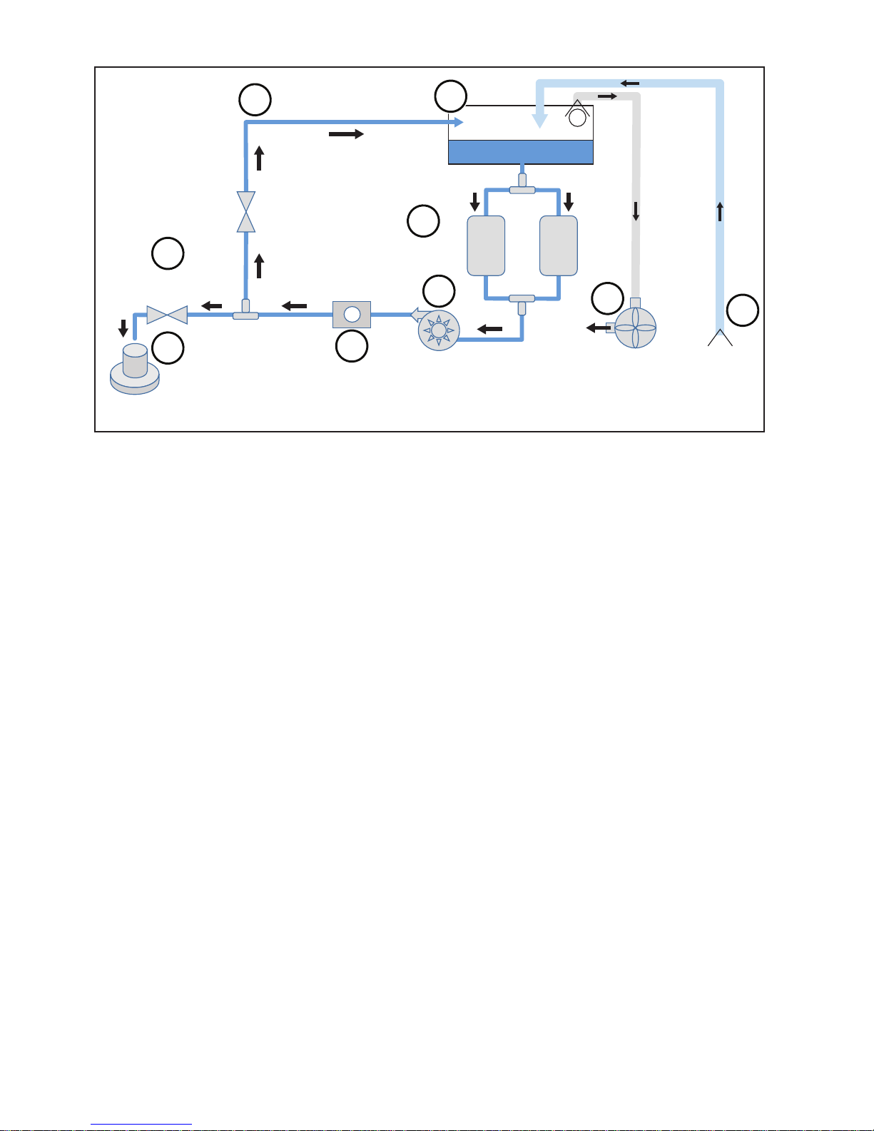
12.1. TASKI Intellibot SWINGOBOT 1650 CE Flow Diagram (Parallel)
10
um
10
um
BYPASS
VALVE
WATER
VALVE
TANK
FLOW
SENSOR
FILTRATION
VACUUM SQUEEGEE
F
CYLINDER
SCRUB
CIRCULATION
PUMP
1
7
4
3
2
8
9
6
5
Figure: 18
1 The robotic oor scrubber system utilizes 53-liter tank for storing and recycling cleaning solution.
2 The standard system uses a parallel canister ltration system with two 10 micron lters. Optional lters are
also available.
3 The circulation pump provides ow for the cleaning solution.
4 A ow sensor is used to detect and set an appropriate ow rate for effective scrubbing.
5 Water valves provide ow regulation for wash water or recycling of the cleaning solution.
6 Cleaning solution is distributed directly onto the scrubbing head.
7 When not scrubbing, the cleaning solution is recycled back to the tank and continually ltered.
8 A vacuum system evacuates air from the top of the tank, providing suction for the vacuum squeegee
9 The squeegee system wipes used cleaning solution from the oor and the pickup tube directs the used
solution back to the tank.

12
12.2. TASKI Intellibot SWINGOBOT 1650 CE UV Flow Diagram (In Series Healthcare Only)
BYPASS
VALVE
WATER
VALVE
TANK
SERIES
FILTRATION
VACUUM SQUEEGEE
SCRUBBER
FLOW
SENSOR
CIRCULATION
PUMP
REACTOR
1
um
10
um
F
BALLAST
DC-TO-AC
INVERTER
UV POWER SUPPLY
1
8
5
3
2
9
10
7
6
4
UV
STERALIZER
Figure: 19
1 The robotic oor scrubber system utilizes 53-liter tank for storing and recycling cleaning solution.
2 The UV ltration system utilizes a 10 micron pre-lter and a 1 micron primary lter to eliminate turbidity for
effective UV penetration into the cleaning solution.
3 The circulation pump provides ow for the cleaning solution.
4 The UV sterilization system includes a power supply, UV ballast, UV lamp, and sterilization reactor to
eliminate microorganisms from the recycled cleaning solution.
5 A ow sensor is used to detect and set an appropriate ow rate for effective scrubbing.
6 Water valves provide ow regulation for wash water or recycling of the cleaning solution.
7 Cleaning solution is distributed directly onto the scrubbing head.
8 When not scrubbing, the cleaning solution is recycled back to the tank and continually ltered.
9 A vacuum system evacuates air from the top of the tank, providing suction for the vacuum squeegee
10 The squeegee system wipes used cleaning solution from the oor and the pickup tube directs the used
solution back to the tank.

13
12.3. Robotic Operation:
The machine uses a number of advanced systems enabling
it to clean robotically.
Figure: 20
A system of 16 individual sonar transceivers
are used for detecting both short-range and
long-range objects to determine the robot’s
environment.
A gyroscopic compass is used to determine
the robotic heading to follow pre-installed or
custom designed cleaning maps.
WiFi and cellular communications are
available for reporting system status and
remote diagnostics.
13. Safety Devices
The robotic oor scrubber system is equipped with the
following safety devices:
13.1. Emergency Stop Button
The Emergency Stop Button is the red switch located on the
top right of the handlebar assembly. Pressing the Emergency
Stop Switch will interrupt power to the system. The operator
should be prepared to press the Emergency Stop Button
at any time to address unintended operation or to avoid a
hazardous situation in an emergency.
1
Figure: 21
1 Emergency Stop Button
13.2. Front Cover Interlock
The front cover interlock is the red magnetic switch located
inside the front cover. The front cover interlock switch will
interrupt power to the system if the front cover should ever
be opened during operation.
Front Cover
(Open Position)
Parking Brake
(Unlocked Position)
Cover Interlock
Switch
Figure: 22
13.3. Parking Brake
The parking brake is located under the machine between the
rear casters. The brake is activated by moving it to the left to
lock the drive wheels.

14
Figure: 23
Moving the handle to the right unlocks the brake. The parking
brake should be locked whenever the machine is not in use.
13.4. Touch shields
The system is equipped with front and rear touch sensitive
panels. If an object bumps into the panels the system will
stop.
1
2
Figure: 24
1 Front Touch Shield
2 Rear Touch Shield
13.5. Warning Lamp
The system is equipped with a yellow warning lamp. The
lamp ashes to alert people when the unit is operating.
1
Figure: 25
1 Warning Lamp Light
13.6. Floor Sensors
The robotic oor scrubber system includes four infrared
oor sensors located underneath the machine. The sensors
measure the distance to the oor at each of the four corners
and are used to detect drops in the oor, such as a stairwell.
1
1
1
1
Figure: 26
1 Infrared Sensor
During robotic operation, the machine monitors this distance
and will stop automatically if the distance exceeds a preset
number.
13.7. Safety Device Warnings
The operator should be aware of the following
warnings regarding the safety devices:
Always set the parking brake when the
machine is not running or unattended.
Do not remove or modify the safety devices
in any way.
Do not open the front cover unless
instructed to do so in this manual

15
14. Safety Circuit Wiring
1
2
4
5
3
70A
BATTERY FUSE
BATTERY BOX
SAFETY
CONTACTOR
FRONT COVER
MAGNETIC INTERLOCK
SAFETY
RELAY
EMERGENCY
STOP BUTTON
MAIN
CONTROLLER
24V
GND
CONTACTOR
STATE
Safety Relay
- 24V
MIRROR
CONTACTS
41
31
2111
12 22 32
42
K1
A1A21 3 5
3
2 4 6
4
F6
R50955
Fuse - Blade 30A - 32V
Bussmann ATC-30
F5
1300573
Fuse - Blade 4A - 32V
Bussmann
BK/ATC-4
F2
1300589
Fuse - Blade 1A - 32V
Bussmann
ATC-1
F1
1300633
Fuse - Blade -
7.5A - 32V
Bussmann
BK/ATC-7 1/2
F1
1300614
Fuse - Blade 15A - 32V
Bussmann
BK/ATC-15
F1
1300614
Fuse - Blade 15A - 32V
Bussmann
BK/ATC-15
CB1
2300129
Circuit Breaker Resettable - 40A
Klixon 7851-1340i
LINEAR MOTORS
AND SOLENOID
BRUSH
MOTORS
VACUUM
MOTORS
RECYCLE
PUMP
UV
LIGHT
I/O
BOARD
DRIVE
MOTOR
(L)
DRIVE
MOTOR
(R)
Figure: 27
1 A safety contactor is used to safely remove power from all motors and the UV sterilizer system
2 The safety contactor is controlled by a safety relay. The safety relay will open the safety contactor when
either the Emergency Stop Button is pressed or the front cover is opened.
3 The system main controller monitors the status of the safety contactor to alert the operator when the circuit
is tripped.
4 A main battery fuse is provided in the battery box to protect the primary power wiring.
5 Branch fuses are provided to protect the branch wiring to each of the motors and subsystems.
Important:
The components of the safety circuit are essential to the safe operation of the machine. Never tamper
with or substitute any safety component, serious damage or injury may result.

16
15. Batteries
The robotic oor scrubber system utilizes a battery pack
containing 4 six-volt gel cell, or AGM deep cycle batteries.
The battery pack is heavy and requires special handling.
Figure: 28
If replacement of the batteries within the battery pack is
needed, contact Customer Assistance. Battery replacement
can be hazardous and should only be performed by a trained
service technician.
Do not attempt to remove the battery pack
from the machine unless you are using
an approved accessory stand or cart The
battery pack weighs 293 lbs (133 kg) and
can cause serious injury.
15.1. Battery Safety
Batteries store a signicant amount of energy and emit
explosive gases when charging. Attention, care, and
planning should be taken when storing and charging this
machine and the battery packs. Review and understand the
warnings shown in the battery warning label section and plan
in advance for battery storage, charging and accidents.
15.2. Accessory Battery Cart
TASKI Intellibot offers an accessory battery cart that allows
for battery pack removal and charging in one station. If a
second battery is also purchased, it can be stored on the
cart and charged while the machine is in use, allowing for
improved efciency.
Figure: 29
When using a charger on the battery cart,
ensure the charger cover is installed to
maintain IPX4 protection.
15.3. Removing the Battery Pack
Before removing the battery, ensure the parking brake is set.
Figure: 30
Turn off the system by pressing the green standby switch
and waiting until the green light is extinguished before
proceeding.
Figure: 31
Before Removing Batteries, hold ~ Standby button,
listen for 3 Beeps, which is the computer acknowledging your
button push. Computer will turn off 24V circuits & start saving
data.
Caution, for the next 30-90 seconds the computer
saves data, wait for button light to go "Off" or you will lose the
data. If light is still on after 120 Seconds, to prevent damage
or injury hit e-stop to assure 24V power is disconnected from
battery before breaking connection by pulling on battery
handle.
Button goes dark; computer has shut down all power.
All power is off; no trickle power is leaking from the battery to
any circuit.
Caution:
If the standby button remains illuminated
for more than 120 seconds, press the
Emergency Stop button before removing
the battery pack.
Attach the accessory cart to the machine.

17
Always lock the wheels on the battery
cart to prevent the cart from moving while
removing the battery from the machine.
Figure: 32
Depress the battery latch and pull the battery from the
system onto the accessory battery cart.
Figure: 33
Attention
Never store the machine with discharged
batteries. Otherwise, the batteries will be
damaged beyond repair. Be sure to fully
charge batteries whenever storing the
machine.
16. Charging
The battery pack may be recharged while in the robotic oor
scrubber system.
Only recommended 24 volt gel cell
battery charging systems should be used.
Overheating, re, and explosion could result
from improper battery charging.
The charge current should be limited to 20
Amps or less. Do not charge the system
with a current higher than 20 Amps or
damage could result.
It is typical of a gel cell charger set at 20
Amps to initially overshoot to as much as
30 Amps and then settle back to around
20 Amps. This is acceptable as long as
it settles back to 20 Amp within a few
seconds.
16.1. Locating the Charger
The location and mounting of the battery charger should be
considered before charging the system or battery pack.
Figure: 34
The battery charger connects to the high
voltage mains. The charger must be located
on a wall, away from wet areas, to avoid a
shock hazard.
Caution
To avoid water shorting the charger it should
be mounted above tank no less than 12"
(31 cm) above, either on a shelf or to the
wall per charger manufacturers instructions.
Periodically inspect the mains and charging
cables to ensure the integrity of the
insulation. Do not use the charger if the
insulation is nicked or cracked.
16.2. Charging the System
Before charging the battery, ensure the parking brake is set.
Figure: 35
Turn off the system by following instructions from "Figure: 31"
on page 16.

18
Caution:
If the standby button remains illuminated
for more than 120 seconds, press the
Emergency Stop button before charging the
system.
Caution:
Never remove battery pack while charging.
Damage to the electronic controls will likely
result!
Locate the system charging port under the rubber ap.
Figure: 36
Plug in the charger and fully charge the batteries.
CHARGER SPECIFICATIONS
MODEL
BATTERY
VOLTAGE
CHARGING
CURRENT
BATTERY RANGE
(5H) (20H)
CBHF2
24-20
24 V 20 A
120÷195 Ah150÷240
Ah
17. Language Setup
The robotic oor scrubber system interface supports
three languages, English, German, and Spanish.
Perform the following to select the system interface
language:
Turn on the system by pressing the standby
button.
Wait approximately 2 minutes until the LOG
IN screen is displayed.
••••••
1 2 3
4 5 6
7 809
x
Press the LOG IN key and enter your
administrative password.
The prep guide will appear. Touch the OK
button to move to the home screen.
Figure: 37
From the home screen, press the right
arrow button to access the system settings
menu.
Press the Prefs button to access system
preferences.
Press the language button and select
English, Spanish, or German.
18. Administrative Setup
The following are instructions for adding operators and
setting operator privileges.
Turn on the system by pressing the standby
button.
Wait approximately 2 minutes until the LOG IN screen is
displayed.

19
Figure: 38
Conrm "CE" is in lower left of screen as a
software update may have occurred since
last use.
If "CE" is not displayed, write down the
serial number and software version,
shut down the machine and then contact
Customer Assistance. Give Customer
Assistance this data and ask for further
instructions.
••••••
1 2 3
4 5 6
7 809
x
Press the LOG IN key and enter your
administrative password.
The prep guide will appear. Press the OK
button to move to the home screen.
Press the Admin button to access the
administrator screen.
Figure: 39
1 Press the Add Operator key to add a new system
operator.
2 To edit operator information press the information
key to access the user setting screen.
3 To inactivate an operator, press the inactivate
operator key. This prevents an operator from
accessing the machine.
4 To edit or delete an existing operator, press the
operator name.
The following buttons are used to grant or revoke privileges
from the user setting screen:
Pressing the manual mode button allows
the operator to use the machine in manual
mode.
Pressing the robotic mode button allows
the operator to use the machine in robotic
mode.
Pressing the mapping button allows the
operator to create new maps and edit
existing maps.
Pressing the reporting button allow s the
operator to view machine statistics.
Pressing the administrative privilege button
allows the operator to add, modify, or delete
other operators.
Pressing the diagnostics button allows the
operator to view machine diagnostics.

20
19. System Preferences
Perform the following to set the WiFi, beeper, language,
measurement system, and water ow rate system
preferences.
Turn on the system by pressing the standby
button.
Wait approximately 2 minutes until the LOG
IN screen is displayed.
••••••
1 2 3
4 5 6
7 809
x
Press the LOG IN key and enter your
administrative password.
The prep guide will appear. Touch the OK
button to move to the home screen.
Figure: 40
From the home screen, press the right
arrow button to access the system settings
menu.
Press the Prefs button to access system
preferences.
Press the WiFi button to congure the
system WiFi. WiFi must be turned on when
the Intelli-Track reporting system is in use.
Press the beeper button to set the safety
beeper on or off. When set to ‘ON’ the
beeper will sound while the machine is
running.
Press the language button to select
English, Spanish, or German for the system
interface.
Press the measurement button to congure
the measurement system to metric or
imperial.
Press the water ow button to congure the
system ow rate from 1.1 to 2.6 liters per
minute.
Press the OK button to exit the system
preference menu.
20. Commissioning After Storage
If the machine has been in storage, the following items must
be reviewed:
The robotic oor scrubber system must be
acclimated to the operating environment.
Failure to do so can result in condensation
inside the machine, shortening the life of
critical components. Allow the machine to
acclimate one hour for every 9° F (5° C).
Gel cell batteries will lose charge if not
maintained while in storage. Ensure the
batteries go through a full charge cycle
before turning on the system.
21. Weekly Safety Device Check
To ensure the safe operation of this machine, the operator
must periodically verify the operation of the system safety
devices. The following operational safety device check
should be performed on a weekly basis.
If any safety device fails the operational
safety device check, the machine must be
serviced by a trained service technician. Do
not use the system if any safety device is
not operating properly.
21.1. Emergency Stop Button Check
Perform the following steps to verify operation of the
Emergency Stop button:
Turn on the system by pressing the standby
button.
Wait approximately 2 minutes until the LOG IN screen is
displayed.
Figure: 41
Press the Emergency Stop button.
Verify that the system alerts the user with
three audible beeps and the user interface
displays the attention symbol and the
words.
Emergency Stop pressed
Twist and release to resume
If the system fails the Emergency
Stop button operational check, turn off
immediately by pressing and holding the
standby button. Do not use the system,
it must be repaired by a trained service
technician.

21
If the system passes the operational
check, twist the Emergency Stop button
counterclockwise to reset and press the OK
button on the user interface.
21.2. Front Cover Interlock Check
Perform the following steps to verify operation of the front
cover interlock:
Verifying the front cover interlock requires
partially opening the front door with the
machine turned on. Do not open the door
more than ¼ of the full swing. If the interlock
fails to operate, personnel may be exposed
to hazards within the machine.
Verify that the LOG IN screen is shown on
the user interface.
Release the two latches on the front cover
and open the door ¼ of the full swing.
Verify that the system alerts the user with
three audible beeps and the user interface
displays the attention symbol and the
words:
Front door open
Close front door to resume
If the interlock operational check fails, press
the Emergency Stop button immediately,
then turn off the system by pressing and
holding the standby button. Do not use the
system, it must be repaired by a trained
service technician.
If the system passes the operational check,
close the front cover and attach both
latches, then press the OK button on the
user interface.
21.3. Parking Brake Check
Perform the following steps to verify operation of the
parking brake:
This procedure requires engaging the drive
in manual mode. Only use the slowest
forward speed to verify operation of the
parking brake. If the parking brake fails,
using a higher speed reverse direction could
result in damage to the machine, property,
or injury to the operator.
Verify that the LOG IN screen is shown on
the user interface and log into the system
using your operator code.
Touch the Manual clean button on the home
screen.
Touch the forward arrow button once to set
the slowest speed.
Squeeze the handlebar for one second,
then release. Verify that the parking brake
is holding and the machine does not drive
forward.
Verify the yellow safety light on top of the
machine ashes while the handlebar is
pressed.
If the parking brake operational check
fails, press the Emergency Stop button
immediately, then turn off the system by
pressing and holding the standby button. Do
not use the system, it must be repaired by a
factory trained service technician.
Turn off the system by pressing and holding
the standby button.
21.4. Touch Shield Check
There are two touch shields. The front touch shield is
attached to the front cover door. The rear touch shield is
attached to the main body of the machine.
1
2
Figure: 42
1 Front Touch Shield
2 Rear Touch Shield
Each touch shield is divided into six zones, front, left front,
right front, rear, left rear, right rear. Each of the six zones
must be tested for operation.

22
6
5
2
3
2
2
Figure: 43
1 Front Zone
2 Right Front Zone
3 Right Rear Zone
4 Rear Zone
5 Left Rear Zone
6 Left Front Zone
Perform the following steps with the system turned on and
the parking brake set.
From the home screen, press the right
arrow button to access the system settings
menu.
Press the diagnostics key to enter the
diagnostics menu.
Press the touch shield button to enter the
touch shield diagnostic.
1
5
2 3 4
6
Figure: 44
1 Zone contact indicator
2 Zone indicator (yellow text)
3 Total number of contact detections since machine
installation (white text)
4 Total number of contact detections since
machines last startup or diagnostics where
performed (orange text)
5 Resets total number of contact detections to 0
since machine last startup
6 Return to diagnostics main screen
Record the orange numbers (4) if needed.
Press the reset button to reset the orange
number counters to zero.
Press each of the six touch shield zones, applying at least
1.5 lbf (6.7 Newtons) of force.
Review the orange number and verify that the machine
recorded each touch.
If the machine does not recognize any
of the touch shield zones it is not safe
to operate in robotic mode. Turn off the
machine by pressing and holding the
standby button. Do not use the system,
it must be repaired by a factory trained
service technician.
Press the reset button to reset the orange
number counters to zero.
Press the forward key to return to return to
the diagnostics menu.
Press the return key to return to the main
menu.
21.5. Floor Sensor Check
There are four infrared sensors that measure the distance
from the machine frame to the oor. The sensor operation is
checked by using the system diagnostics menu.
Perform the following steps with the system turned on and
the parking brake set.
From the home screen, press the right
arrow button to access the system settings
menu.
Press the diagnostics key to enter the
diagnostics menu.
Press the oor sensor button to enter the
oor sensor diagnostic.

23
1
4
2
3
Figure: 45
1 Reports sensor distance in mm
2 Reports sensor voltage in mV
3 Sensor
4 Return to diagnostics main screen
Verify that all four of the sensors report a reasonable
distance to the oor and the “No ground” warning is not
displayed.
It is possible to receive a false “no ground”
warning on black shiny surfaces. If the
oor is causing false readings, move the
machine to a different location to perform
the test.
If the machine does not recognize any
of the sensors it is not safe to operate In
robotic mode. Turn off the machine by
pressing and holding the standby button. Do
not use the system, it must be repaired by a
factory trained service technician.
22. Daily Startup Procedure
The following procedure should be performed daily before
operating the robotic oor scrubbing system.
22.1. Set the Parking Brake
Ensure the parking brake is in the locked position by moving
the red lever to the left.
Figure: 46
22.2. Power Off
Ensure the machine is turned off.
22.3. Remove Charging Cable
If the system is being charged, disconnect
the battery charging cable from the system
charging port.
The machine will not turn on with the
charger mechanically connected.
22.4. Remove Empty Canisters
Remove both canisters using the supplied wrench.
1
1
2
Figure: 47
1 Cannister Filters
2 Filter Wrench
22.5. Install Clean Filters
Install clean lters and ensure they are seated properly in
each canister.
Filter elements should be replaced every
30 days.
The TASKI Intellibot SWINGOBOT 1650 CE
UV utilizes a series ltration system. The
10-micron pre-lter must be installed in the
left canister and the 1-micron primary lter
must be installed in the right canister.
22.6. Install Canisters With Filters
Ensure the black rubber O ring is on the
interior lip of each blue canister. Seat the
canister, hand tighten, and use the lter
wrench to provide an additional 1/4 turn.

24
22.7. Inspect Squeegee
Check the squeegee blades for wear.
Flip worn blades and replace if necessary.
22.8. Inspect and Replace Scrubber Pads
Unlatch and open the front cover. Inspect the scrubber pads.
Replace if pads are worn to within 10 mm of brushes.
To replace the pads, rotate the brushes toward the center of
the machine to release the brush.
Figure: 48
Replace the pad on the brush. Replace the brush on the
head by rotating in the opposite direction.
Inspect pads for wear and replace if
necessary.
Flip the pads every other day to extend
brush life.
Close the front door and secure both latches.
22.9. Fill the Tank
Fill the tank with 14 gallons (53 liters) of cool water.
Diversey recommends using cold water
since hot water will adjust to the oor
temperature as soon as it is in contact with
the oor. Thus there are no advantages to
the using of hot water.
Add recommended cleaning solution
to the water in the tank according to
the manufacturer’s instructions. Use of
protective glasses, gloves, and apron is
recommended.
Only use cleaning products recommended
by TASKI Intellibot. Use of products
containing chlorine, acids, or unsuitable
solvents may damage the machine and
may be hazardous to the operator.
22.10. System Power Up
Perform the following steps to power up the system.
Turn on the system by pressing the standby
button.
Wait approximately 2 minutes until the LOG IN screen is
displayed.
Figure: 49
Conrm "CE" is in lower left of screen as a
software update may have occurred since
last use.
••••••
1 2 3
4 5 6
7 809
x
Press the LOG IN key and enter your
operator password.
You will be prompted with a series of
screens to guide you through machine
preparation steps. Touch any of these
screens for more information.
Release the parking brake by moving the red lever to the
right.
Figure: 50
Press the OK button to begin using the
machine.
23. Review of Work Area
Before beginning cleaning, the operator is responsible for
reviewing and preparing the work area.
Remove any objects from the oor that
could get caught or be thrown by the
scrubber head. Objects entangled or
thrown by the scrubber could cause serious
property or machine damage and injury.

25
Block all stairways and doorways when
using robotic mode. Failure to block a
stairway could result in the machine
tumbling down the stairs, resulting in serious
property damage, machine damage and
injury.
24. Manual Drive
The machine must be manually driven to the cleaning
area and placed at the cleaning start location. To manually
transport the machine, perform the following:
From the home screen, press the manual
clean button
Press the forward or reverse arrow buttons
to set the desired speed then squeeze the
handlebar to engage the drive system.
Take care when reversing to prevent
tripping over object or trapping the operator
between the machine and an object.
To prevent accidental movement, the
handlebar must be squeezed within 4
seconds of selecting a speed. If the timer
has elapsed, select the speed again and
squeeze the handle within 4 seconds.
The system uses a gyroscopic inertia sensor to sense
operator input for steering. Pull the handlebar left or right
and the machine will respond by turning in the appropriate
direction.
Release the handlebar to stop.
25. Manual Cleaning
Use the following functions to operate the machine in manual
clean mode:
From the home screen, press the manual
clean button.
Press the vacuum button to lower the
squeegee and turn on the vacuum system.
Press the scrubber button to lower the head
and activate the scrubber motors.
Press the forward arrow button to set the
desired speed then squeeze the handlebar
to engage the drive system.
26. Hands Free Cleaning
Three options are available for hands free cleaning, Spot
Clean, Area Clean, and Map Clean.
MODE
WIDTH (MIN) WIDTH(MAX)
END WALL
FT M FT M
Spot
Clean
5.58 ft 1.7 m 60 ft 18.3 m NO
Area
Clean
5.58 ft 1.7 m 60 ft 18.3 m YES
Spot Clean is used to robotically clean a dened area when
no end wall is present. There must be a left and right wall
present for the machine to accurately measure the width of
the cleaning area. The machine will clean the area between
the side walls to an operator set distance between 20 ft and
196.18 ft (6.1 meters and 60.1 meters.).
Area Clean is used to robotically clean an area when an end
wall or obstacle is present. The machine robotically cleans
according to any one of twelve selectable built-in cleaning
patterns.
Map Clean allows an authorized operator to create a custom
cleaning pattern for robotic cleaning.
26.1. Spot Clean
Using the Manual Drive mode, position the machine at the
cleaning start location. To enable Spot Clean, perform the
following from the home screen:
Press the Spot Clean button and use the
(+) and (-) buttons to select a spot cleaning
distance from 20 ft and 196.18 ft (6.1 meters
and 60.1 meters.).
GO
Press the GO button and the machine will
begin robotic cleaning.

26
26.2. Area Clean
Area clean uses any of twelve different cleaning patterns
with the option of having the machine return to the starting
location when the cleaning is complete. For example the
following is a Side T Right cleaning pattern:
Figure: 51
The machine starting location is shown as (3). The machine
ending location is shown as (4).
Figure: 52
Alternately, the same Side T Right pattern can be chosen
with the machine returning to the start location (2)

27
The following cleaning patterns are available:
Single Area
Single Area Return
Side T Right
Side T Right Return
L Left
L Left Return
Side T Left
Side T Left Return
L Right
L Right Return
Cross Left
Cross Left Return
T Left
T Left Return
Cross Right
Cross Right Return
T Right
T Right Return
U Style Right U Style Right Return
Large Room Large Room Return U Style Left U Style Left Return
Figure: 53

28
Using the Manual Drive mode, position the machine at the
cleaning start location. The machine must be located within
2 ft (61 cm) of start location shown on cleaning pattern.
To enable Area Clean, perform the following from the home
screen:
Press the Area Clean button and choose an
area cleaning pattern.
GO
Press the GO button and the machine will
begin robotic cleaning.
After the GO button is pressed the machine will spend a few
moments calculating the cleaning plan before proceeding
robotically. The machine will continue to clean until it reached
the end of the cleaning pattern.
To interrupt the cleaning pattern, press the
PAUSE button.
GO
To resume the cleaning pattern after a
pause, press the GO button.
To terminate the cleaning pattern, press the STOP button.
On the rst pass of the cleaning area, the machine is looking
for openings that match the selected pattern. If the openings
are not found, the machine will stop.
If the machine nds a partial match, it will clean the area
corresponding to the map and then stop.
26.3. Map Clean
Map Clean utilizes custom cleaning patterns created and
downloaded to the machine by authorized operators. To
enable Map Clean:
Using the Manual Drive mode, position the machine at the
cleaning start location. The machine must be located within 2
ft (61 cm) of the start location shown on the cleaning pattern.
Press the Map Clean button and chose a
custom cleaning pattern.
GO
Press the GO button and the machine will
begin robotic cleaning.
After the GO button is pressed the machine will spend a few
moments calculating the cleaning plan before proceeding
robotically. The machine will continue to clean until it reached
the end of the cleaning pattern.
To interrupt the cleaning pattern, press the PAUSE button.
GO
To resume the cleaning pattern after a
pause, press the GO button.
To terminate the cleaning pattern, press the STOP button.
On the rst pass of the cleaning area, the machine is looking
for openings that match the selected pattern. If the openings
are not found, the machine will stop.
If the machine nds a partial match, it will clean the area
corresponding to the map and then stop.
27. Daily Shutdown Procedure
After completing cleaning, the following steps should be
performed daily:
Use of protective glasses, gloves, and
apron is recommended when in contact with
waste water or cleaning any element of the
system.
27.1. Parking
Use manual drive to position the machine next to the
disposal area.
Ensure the scrubber is turned off and the scrubber heads are
in the up position.
Ensure the vacuum is off and the squeegee is in the up
position.
Place the parking brake in the locked position by moving the
red lever to the left.
Figure: 54
Turn off the system by pressing and holding
the standby button.
27.2. Drain and Clean the Tank
Before draining the tank, take note of any
local or national regulations for disposal.
Waste water must be disposed of in a
responsible manner, consistent with
applicable environmental and safety
regulations.
Locate the drain hose, remove the end
from the holder and position the drain hose
over the disposal area.
Pull the drain valve and drain the waste
water into the disposal area.
Clean out debris and sediment from the
basket lter and bottom of tank.

29
Flush the tank with clean water and lose the drain valve.
27.3. Clean the Squeegee:
Clean the squeegee by removing any debris between the
squeegee blades.
Check the pickup tube for obstructions.
27.4. Clean Caster Wheels
Inspect and clean the rear caster wheels
Figure: 55
27.5. Remove and Clean Filters
Remove both canisters using the supplied lter wrench.
Remove the lters from the canisters and
replace the canisters on the system and
the lter wrench in it’s holder.
Rinse and dry the lters to prepare for next
use.

30
28. Maintenance
The following maintenance schedule should be followed for proper machine operation:
MAINTENANCE ITEM DAILY WEEKLY
□ Drain and clean tank X
□ Clean tank basket lter X
□ Remove and clean canister lters X
□ Clean squeegee and pick up area X
□ Inspect pick up tube for obstructions X
□ Inspect squeegee for wear and adjust, ip, or replace as necessary X
□ Clean caster wheels X
□ Inspect pads and brushes for wear. Flip or replace as necessary. X
□ Perform Emergency Stop Button check X
□ Perform front cover interlock check X
□ Perform parking brake and safety light check X
□ Perform touch shield check X
□ Perform the oor sensor check X
□ Replace canister lters X
□ Inspect pickup hose and replace as necessary X
□ Inspect hinges and lubricate as necessary X
□ Apply grease to squeegee pivot bracket X
□ Inspect battery box ball bearings and lubricate if necessary X
□ Clean undercarriage X
28.1. Daily Maintenance Points
• Strainer Basket
Empty large items into the trash and rinse thoroughly.
• Primary Solution Filter
Remove the primary solution lter from the machine. Rinse and gently clean dirt and debris from the lter
using a soft bristle brush.
• Blue Secondary Filters
Remove both blue secondary lters from the back of the machine. Rinse and clean both lters. Allow
lters to air dry if possible. Visually inspect the condition of both lters and replace as necessary
• Squeegee Assembly
Disconnect the squeegee assembly from the SWINGOBOT 1650. Rinse the squeegee and wipe clean.
Hair and other debris may hinder results by leaving streaks on the oor. Visually inspect the condition of
the squeegee blades and rotate or replace as necessary. Check the condition of the frame gasket and
replace as necessary.
• Pads & Brushes
Remove pads or brushes from the machine. Rinse thoroughly and replace as needed.
• Solution Tank Seals
Clean and visually inspect the solution tank seal.
• Solution Tank
Tank should be drained, rinsed and cleaned at the end of every shift.

31
29. Replacement Components
TASKI NO. INTELLIBOT SKU ITEM
7523968 049870 Filter - Cotton 10 Micron
7523969 1300165 Filter - Pleated 1 Micron
7523970 1300755 Filter - Cotton 20 Micron 10"
4132145 3300051 Front Blade - Squeegee - Linatex - SS
4132144 3300052 Rear Blade - Squeegee - Linatex - SS
4132108 1300027 Pad 15" Scrubbing Red
N/A 1300066 Pad 15" Scrubbing White
30. Storage
The following items should be taken into consideration when storing the robotic oor scrubbing system.
ENVIRONMENT
Temperature 59° to 86° F (15° to 30° C) operation, -22° to 140° F (-30° to 60° C) storage
Humidity 20% to 75% relative humidity
Attention
Never store the machine with discharged batteries. Otherwise, the batteries will be damaged beyond
repair. Be sure to fully charge batteries whenever storing the machine.
31. Troubleshooting
MALFUNCTION POSSIBLE CAUSES TROUBLESHOOTING
Machine without function
Charger plugged into robot • Unplug the charger
Battery pack not engaged • Push battery pack into place
Battery not charged • Load batteries
Leaving water
Water ow set too high
• Go to settings menu; lower water valve setting
default
Dirty squeegee
• Wipe squeegee with rag
• Flip or replace squeegee blade (can be
ipped up to 3 times before replacement)
Navigation issues
Sonar faulty • Perform sonar diagnostic, clean sonar
Mechanical drag • Inspect casters
Not cleaning oor surface Brush motor not running
• Reset circuit breaker
• Verify no obstacles are trapped in brush head
Machine pulling to one side when
manually driving
Parking brake is not fully
disengaged
• Move parking brake lever all the way to the
left, then all the way back to the right
If solution fails to correct the
problem
• Contact your service partner

32
32. Diagnostics
The following diagnostics may be performed by operators
with diagnostic privileges.
Perform the following steps with the system turned on and
the parking brake set.
From the home screen, press the right
arrow button to access the system settings
menu.
Press the diagnostics key to enter the
diagnostics menu.
Press the help button and any of the
diagnostics buttons to receive help on that
item. Press the help button again to turn off
the help text.
Press any of the diagnostics buttons to start
the diagnostic. Press the return key to return
to the home screen.
The following diagnostics are available:
Sonar: Reports each sonar distance
measurement.
Touch shield: Reports information on touch
shield contacts.
Floor Sensors: Reports oor sensor
measurements.
Gyro: Reports the compass heading of the
machine.
Wireless: Reports the wireless network
strength and IP address.
Memory: Reports the amount of computer
memory used.
Outputs: Allows temporary control of each
motor, actuator, light, and brake.
Flow: Reports the ow rate of cleaning
solution dispensed onto the scrubber head.
Drive Motor: Reports the speed of each
drive wheel.
33. Sonar Diagnostic
The sonar diagnostic shows the distance
measured in millimeters, by each of the 17
sonar transceivers (numbered 0-16).
1
3
5
6
7
4
2
Figure: 56
1 Sonar number
2 Detected distance
3 Location on machine
4 Software version
5 Next higher number
6 Next lower number
7 Return to diagnostics
Select the sonar using the up and down keys (5) and (6).
The sonar number (1) and the measured distance (2) are
shown on the display. A sonar wave animation (3) is used
to illustrate the location of the sonar on the machine. If the
detected object is outside of the sonar sensor detection
range, the diagnostic will report “—“.
Short range sensors 0-6 and 10-16 can detect a minimum
distance of 80 mm and a maximum distance of 9000 mm.
Long range sensors 7 and 10 can detect a minimum
distance of 200 mm and a maximum distance of 900 mm.
34. Touch Shield Diagnostic
The touch shield diagnostic utility provides
information on total touch shield contacts
and allows for the test of each touch shield
zone. A touch shield must be pressed with
more than 1.5 lb f (6.7 N) force to recognize
contact with the zone.

33
1
5
2 3 4
6
Figure: 57
1 Active zone
2 Zone list
3 Total contacts since installation
4 Contacts since startup
5 Reset contacts since startup
6 Return to diags
The white number shows total contacts with the zone
since machine installation. The orange numbers show total
contacts since startup. The orange numbers can be reset to
zero by using the reset key (5).
35. Floor Sensor Diagnostic
The oor sensor diagnostic provides
information on and allows for testing of the
four infrared oor sensors. The diagnostic
illustrates the location of each sensor and
provides the voltage and detected distance
to the oor for that sensor.
1
4
2
3
Figure: 58
1 Distance to oor
2 Sensor voltage
3 Sensor location
4 Return to diagnostics
If the sensor is located over a drop, such as a downward
stair, the diagnostic will report “No ground” for that sensor.
It is possible to receive a false “no ground” warning on some
surfaces. If the oor is causing false readings, move the
machine to a different location to perform the diagnostic.
36. Gyro Diagnostic
The gyro diagnostic requires machine
rotation it should only be performed in
an open area where the machine can be
rotated 360 degrees with room for the
operator.
2
4
5 7
6
3
1
Figure: 59
1 Current heading: Heading reading in degrees and
hundredths of a degree
2 Scale factor
3 Reset button
4 Clockwise machine rotation
5 Counterclockwise machine rotation
6 Center value
7 Return to diagnostics main screen
36.1. Verifying Gyro Operation
The machine heading is indicated by the compass (1) on the
diagnostic display. Zero the heading by pressing the reset
key (3).
Pressing the left arrow key (4) will cause the machine to
rotate slowly anti-clockwise. The heading will read negative
degrees of rotation.
Rest the heading by pressing the reset button (3).
Pressing the right arrow key (6) will cause the machine
to rotate slowly clockwise. The heading will read positive
degrees of rotation.
Record the ‘’Center’ value reported on the display (6). If
the number is less than 3000 or greater than 5000 contact
customer assistance.
37. Gyro Calibration
IF a gyro problem is suspected, record the numbers
displayed for ‘Scale Factor’ (2) and ‘Center’ (6). Report these
values to customer assistance.

34
Caution:
Do not change any of the gyro calibration
parameters unless instructed to do so by a
trained service technician. Gyro parameters
affect machine performance and stability.
Unauthorized changes could result in
unexpected machine behavior, resulting in
damage or injury.
38. Network Diagnostic
The following provides detail on the network diagnostic:
The network diagnostic is used to review
parameters and signal strength for the
machine WiFi and cellular network
connections.
1 2
Figure: 60
1 Select either WiFi or cellular modem for network
communications
2 Return to diagnostics
Press the selection key (1) to select either WiFi or cellular
modem for network communications. The display will change
to show parameters and signal strength for the chosen
method.
39. WiFi Diagnostic
When using WiFi network communications the network may
be congured with a ‘Managed’ IP address that allows for
connection to an external network or an ‘Ad-Hoc’ IP address
for local wireless connection.
Figure: 61
An ‘Ad-Hoc’ IP address should only be used by a trained
service technician. The machine should always be
congured using a ‘Managed’ IP address during normal use.
Figure: 62
40. Memory Diagnostic
The memory diagnostic is used to view
the current usage of the robotic scrubbing
system’s computer memory.
1
Figure: 63
1 Return to diagnostics
If the diagnostic reports memory usage in excess of 80%,
please contact customer assistance.

35
41. Outputs Diagnostic
The outputs diagnostic is used to aid in
system troubleshoot by allowing privileged
operators to turn on specic machine
devices and verify their operation.
5
4
2 3
1
Figure: 64
1 Output on/off button
2 Cycle backward through output screens
3 Cycle forward through output screens
4 Battery voltage display
5 Return to diagnostics main screen
Cycle through the output screens by pressing the next (3)and
previous (2) keys. Press the desired output (1) to cycle on or
off.
The current battery voltage (4) is displayed during the
diagnostic test.
42. Flow Diagnostic
The ow diagnostic allows for testing and
troubleshooting of the pumping system.
Figure: 65
Pressing the up (1) arrow will increase the system ow rate
and start a priming cycle. The cycle may be terminated by
pressing the down arrow (2).
Priming may take up to two minutes. A priming failure may
indicate an air leak in the plumbing, check for loose canisters
or missing o-rings and restart the diagnostic.
Once priming is complete, the measured ow rate should be
within 0.03 gpm (0.11 lpm) of the expected ow rate.
43. Drive Motor Diagnostic
The drive motor diagnostic utility provides
information used by a trained service
technician to calibrate the drive motors.
1
2
3
4
5
6 67
8
9
10
Figure: 66
1 Amplier status indicator
2 Encoder counts
3 Speed mm/s
4 Average mm/s
5 Command mm/s
6 Audible alert
7 Anti-drift
8 Step the command speedup
9 Step the command speed down
10 Return to diagnostics main screen
The diagnostic can be used to verify the status of the drive
ampliers by checking the Status lights (1). Green lights
indicate the drive amplier is operational, a red light indicates
a fault.

36
44. Technical Data
MACHINE AMOUNT UNIT AMOUNT UNIT
Working width 29.13 in 74 cm
Suction nozzle width 35.04 in 89 cm
Dimensions (L x W x H)
48.42
x 32.28
x 43.31
in
123 x
82 x
110
cm
Maximum weight of operational machine 1133.18 lbs 514 kg
Rated voltage 24V DC 24V DC
Rated power, nominal 1248 W 1248 W
Fresh water tank, nominal +/ 5% 14 gal 53 l
Transportation Weight No Batteries 450 lbs 204 kg
Machine weight with traction batteries (transport weight)
(no water)
743 lbs 337 kg
Sound pressure level Less than 75 dB(A) Less than 75 dB(A)
Splash water guard IPX4 IPX4
Protection class III III

37
45. Revisions
Date Section Content Description Rev
01-06-17
"10. Healthcare/UV
User and Service
Personnel Warnings"
on page 8
Text/copy UV/Healthcare Warnings Section Added B
01-06-17 Cover Image Large "Taski" Decal removed from Front Cover of Machine B
 Loading...