

Task Force Tips XFIH-E8 A, XFIH-E1 A, XFIH-E7 A, XFIH-E4 A, XFIH-E2 A Instructions For Installation, Safe Operation And Maintenance
...Page 1
®
MANUAL: Remote Control
HURRICANE RC MONITOR
INSTRUCTIONS FOR INSTALLATION, SAFE OPERATION AND MAINTENANCE
Read instruction manual before use. Operation of this device without understanding the manual
DANGER
and receiving proper training is a misuse of this equipment. A person who has not read and
understood all operating and safety instructions is not qualified to operate the Hurricane RC
monitor.
Maximum recommended inlet
pressure is 200 psi. (14 bar)
DANGER
PERSONAL RESPONSIBILITY CODE
The membercompaniesof FEMSAthat provide emergencyresponse equipment
and services wantresponders to knowand understand thefollowing:
1. Firefighting and Emergency Response are inherently dangerous activities
requiring proper training in their hazards and the use of extreme caution at all
times.
2. It isyour responsibility to read andunderstand anyuser’s instructionsprovided
with any pieceof equipment youmay be calledupon to use.
3. It is your responsibility to know that you have been properly trained in
Firefighting and /or Emergency Response and in the use, precautions, and
care of anyequipment you maybe called uponto use.
4. It is your responsibility to be in proper physical condition and to maintain the
personal skill level required tooperate any equipment you maybe called upon
to use.
5. It isyour responsibilityto knowthat yourequipment isin operablecondition and
has been maintainedin accordance withthe manufacturer’s instructions.
6. Failure to follow these guidelines may result in death, burns or other severe
injury.
FEMSA
Fire and Emergency Manufacturers and Services Association, Inc.
P.O. Box 147, Lynnfield, MA 01940 • www.FEMSA.org
TASK FORCE TIPS, Inc.
MADE IN USA • www.tft.com
©Copyright Task Force Tips, Inc. 2004-2006
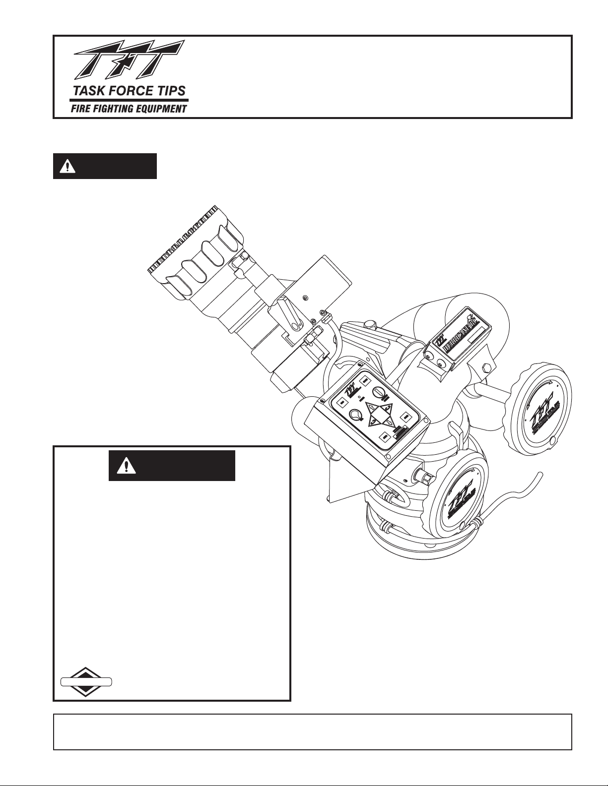
Model XFIH-E11A Monitor
Shown With
Model M-ERP-NJ Nozzle
This instruction manual is intended to familiarize installers,
firefighters and maintenance personnel with the installation,
operation, servicing, and safety procedures associated with
the Hurricane RC Monitor.
This manual should be kept available to all operating and
maintenance personnel.
2800 E. Evans Ave., Valparaiso, IN 46383-6940 USA
800-348-2686 • 219-462-6161 • Fax 219-464-7155
LIX-300 January 24, 2006 Rev05
Page 2

Table of Contents
1.0 MEANING OF SAFETY SIGNAL WORDS ........................3
2.0 SAFETY ...................................................3
3.0 GENERAL INFORMATION ....................................3
3.1 SPECIFICATIONS ......................................3-4
3.1.1 MECHANICAL SPECIFICATIONS
3.1.2 ELECTRICAL SPECIFICATIONS
3.2 PART IDENTIFICATIONAND MODELS .......................4
3.3 INLETS AND OUTLETS..................................5-6
3.3.1 INLET FLANGE SIZE SPECIFICATIONS
3.4 OVERALL DIMENSIONS ..................................6
3.4.1 OVERALL HEIGHT INCREASE FOR INLET FITTINGS
3.5 ELECTRICAL CONTROLS .................................7
3.5.1 MOTOR CONTROL BOARD (MCB) AUTO CONFIGURE
3.5.2 MOTOR CURRENT LIMITING
3.5.3 MOTOR SOFT STOPS
3.5.4 MOTOR SLOW/FAST SPEED
3.5.5 COMMUNICATION PROTOCOL
3.5.6 OSCILLATE AND STOW FEATURES
4.0 INSTALLATION 7-8
4.1 STRUCTURAL REQUIREMENTS FOR MONITOR MOUNTING ....7
4.2 INLET FITTINGS or EXTEND-A-GUN RC INSTALLATION ......8-9
4.3 NOZZLE CONNECTION ..................................10
4.4 HORIZONTAL ROTATION TRAVEL STOPS ................10-11
4.5 PRESSURE GAGE PORT.................................11
4.6 AUTOMATIC DRAIN .....................................11
5.0 ELECTRICAL CONTROLS INSTALLATION......................12
5.1 PRIMARY MONITOR OPERATOR STATION ...............13-14
5.1.1 MOUNTING
5.1.2 ELECTRICAL WIRING
5.2 OPTIONAL MONITOR OPERATOR STATIONS................15
5.2.1 MOUNTING
5.2.2 ELECTRICAL WIRING
5.3 TETHER MONITOR OPERATOR STATION ................15-16
5.3.1 HOLSTER MOUNTING
5.3.2 RECEPTACLE MOUNTING
5.3.3 ELECTRICAL WIRING
5.4 WIRELESS MONITOR OPERATOR STATION .................16
5.4.1 MOUNTING RECEIVER
5.4.2 ELECTRICAL WIRING RECEIVER
5.4.3 MOUNTING CHARGING CRADLE
5.4.4 ELECTRICAL WIRING CHARGING CRADLE
5.5 JOYSTICK MONITOR OPERATOR STATION ...............17-18
5.5.1 MOUNTING
5.5.2 ELECTRICAL WIRING
5.5.2.1 WIRING TO A COMMUNICATION INTERFACE BOX
5.5.2.2 WIRING TO PRIMARY OPERATOR STATION
5.6 TOGGLE SWITCH MONITOR OPERATOR STATION ...........18
5.6.1 ENCLOSURE MOUNTING
5.6.2 ELECTRICAL WIRING
5.7 COMMUNICATION INTERFACE BOX .......................19
5.7.1 ENCLOSURE MOUNTING
5.7.2 ELECTRICAL WIRING
5.7.3 INPUT SIGNAL CONFIGURATION
5.8 MONITOR POSITION DISPLAY ............................19
5.9 CONNECTING MONITOR CABLE DIRECTLY TO PROTECTED
POWER SUPPLY .......................................19
5.9.1 ELECTRICAL WIRING
5.10 OPERATOR STATION INSTALLATION DIRECTLY TO MONITOR...20
5.11 HURRICANE RC AERIAL TRUCK INSTALLATION ............20-21
5.11.1 ELECTRONICS ENCLOSURE MOUNTING
5.11.2 ELECTRICAL WIRING
5.11.2.1 LADDER INSTALLATION ELECTRICAL WIRING
5.11.2.2 PLATFORM INSTALLATION ELECTRICAL WIRING
5.12
ELECTRICAL NOZZLE ACTUATOR WIRING ...................21
6.0 OPERATION ................................................21
6.1 MANUAL OVERRIDE HANDWHEELS .........................22
6.2 ELECTRICAL MODEL ...................................22-24
6.2.1 OPERATOR STATIONS
6.2.1.1 MONITOR MOUNTED OPERATOR STATION
6.2.1.2 PRIMARY OPERATOR STATION
6.2.1.3 OPTIONAL OPERATOR STATION
6.2.1.4 TETHER OPERATOR STATION
6.2.1.5 WIRELESS OPERATOR STATION
6.2.1.6 JOYSTICK OPERATOR STATION
6.2.1.7 TOGGLE SWITCH OPERATOR STATION
6.2.2 MASTER OVERRIDE FEATURE
6.2.3 STOW FEATURE
6.2.3.1 PROGRAMMING
6.2.3.2 STOW PROGRAMMING EXAMPLE
6.2.4 OSCILLATE FEATURE
6.2.4.1 PROGRAMMING
6.2.4.2 OSCILLATE PROGRAM RETAIN FEATURE
6.2.5 OPERATOR STATION PANELS
6.3 RECOMMENDED MONITOR STOWING POSITION ..............25
6.4 AUTOMATIC DRAIN .......................................25
6.5 FLOWS & PRESSURES .................................25-29
6.5.1 STACKED TIPS FLOWAND REACH
6.5.2 AUTOMATIC NOZZLES
6.5.3 HURRICANE RC MONITOR FRICTION LOSS
6.6 STREAM STRAIGHTENERS ................................29
6.6.1 STREAM STRAIGHTENERS WITH STACKED TIP NOZZLES
6.6.2 STREAM STRAIGHTENERS WITH FOG NOZZLES
7.0 TROUBLESHOOTING .........................................30
8.0 MAINTENANCE AND INSPECTION ..............................31
8.1 LUBRICATION............................................31
8.1.1 ELEVATION CONTROL WORM GEAR
8.1.2 HORIZONTAL ROTATION WORM GEAR
8.2 PERFORMANCE TESTING .................................31
9.0 EXPLODED VIEW DRAWINGS AND PARTS LIST ................32-35
9.1 HURRICANE RC MONITOR ASSEMBLY ....................32-33
9.2 ELEVATION CHAIN DRIVE ASSEMBLY........................34
9.3 GEAR MOTOR ASSEMBLY .................................34
9.4 MONITOR CONTROL BOX ASSEMBLY........................35
10.0 WARRANTY.........................................Back Cover
2
Page 3
1.0 MEANING OF SAFETY SIGNAL WORDS
A safety related message is identified by a safety alert symbol and a signal word to indicate the level of risk involved with a
particular hazard. Per ANSI standard Z535.4-1998, the definitions of the three signal words are as follows:
DANGER indicates an imminently hazardous situation which, if not avoided, will result in death or
DANGER
WARNING
CAUTION
serious injury.
WARNING indicates a potentially hazardous situation which, if not avoided, could result in death
or serious injury.
CAUTION indicates a potentially hazardous situation which, if not avoided, may result in minor or
moderate injury.
2.0 SAFETY
The operation of this monitor can be dangerous. The following must beobserved at all times.
Injury can result from an inadequately supported monitor. The monitor mount must be capable of
WARNING
CAUTION
CAUTION
CAUTION
supporting 1500 lbs (700 kg) of nozzle reaction force.
The stream exiting a monitor is very powerful and capable of causing injury and property damage.
Make sure the monitor is securely attached to the base and pointing in a safedirection before water
to the monitor is turned on. Use care in directing the stream.
The electric Hurricane RC may be remotely operated. The electric drives are current limited but
may still produce enough force to cause injury. Keep hands and fingers away from pinch points on
the monitor.
Do not use the manual override handwheels while the electric controls are in operation. The
electric drives produce enough torque to cause injury.
Maximum pressure is 200 psi (14 bar). Damage or injury may result if the monitor is operated
CAUTION
On many vehicle installations the monitor is the highest point on the apparatus. Often it is critical that the monitor be properly stowed
before driving to avoid damage to overhead obstructions such as door openings. In these cases the use of a switch wired into the
apparatus "door open" circuit is highly recommended. The switch should be wired to give a "door open" signal if the monitor is not in the
stowed position. Due to the variety of possible mountings and nozzles, it is the installer's responsibility to supply the appropriate switch
with mounting and wire it into the system.Always check stowed position of the monitor before moving the apparatus.
beyond these limits.
3.0 GENERAL INFORMATION
The Task Force Tips’ HURRICANE RC is an electric remote monitor, with a single low-profile waterway discharge. It has high flow and
low friction loss characteristics. Capable of flowing 1250gpm (4500 l/min)while maintaining a FULL 450° of rotational travel (225° either
side of center position). Maximum operatingpressure is200 psi (14 bar). Fieldchangeable horizontal rotation stops at 45°, 90° and135°
either side of center position. Elevation range is 90° above horizontal and 45° below. Designed for field changeable 12 or 24 VDC
operation. The Hurricane RC comes with a factory installed control panel mounted on the monitor for controlling horizontal rotation,
elevation and nozzle pattern. See Task Force Tips’ Price List and Product Specifications for additional control stations. Unit comes with
30 feet of ultra-flexing robotic cable, enclosed in a unique wire guide, already wired to the monitor so installation effort is minimized.
Large handwheels are provided on the horizontal rotation and elevation drive for manual override. TFT's Master Stream 1250 nozzle
plugs into the factory installed nozzle power wire.All electrical components affecting water tightness are a minimum of NEMA4 (IP65).
Motors and control boxes are factory tested for water tightness.Available with various inlet adapters for flanges and thread fittings. Inlet
also made for direct connection to TFT's Extend-A-Gun RC3 or RC4. Standard outlet is 2-½” National Hose male (65mm). Other outlets
are available (see figure 3.3). A threaded port (0.25” NPT) (6.4mm) is provided for pressure gauge. The monitor is made from hardcoat
anodizedANSI 356.0-T6 aluminum and silver powder coat finish inside and out.
3.1 SPECIFICATIONS
3.1.1 MECHANICAL SPECIFICATIONS
Weight 39 lbs 17.7 kg
Min. Flow Area 7.07 in 45.6 cm - 3” inlets
Max Flow 1250 gpm 4500 l/min
Max Operating Pressure 200 psi 14 bar
Materials Used ANSI 356.0-T6 Aluminum, Stainless, Nylon
22
3
Page 4
3.1.2 ELECTRICAL SPECIFICATIONS
Nominal Operating voltage: 12 or 24 VDC
Motor current: Nominal* Limit
Elevation motor: 6 amps 15 amps
Horizontal rotation motor: 6 amps 10 amps
Nozzle motor: 1 amp 5 amps
At rest current: .25 amps
Recommended fuse or circuit breaker size: 15 amps @ 12 volts, 7.5 amps @ 24 volts
Operating temperature range: -30°F to +120°F (-34°C to +49°C)
Environmental Rating: All components designed to meet minimum rating of NEMA 4 (IP65).
Wireless Operator Station
Charging Cradle
Nominal Operating Voltage 12 or 24 VDC
Operating Current 0.15 amps
Recommended Fuse or Circuit Breaker 2 amps
Transmitter Batteries Uses four (4) AA NiCad Batteries
Transmitter Power 5mW
Operating Frequency 2.4 GHz
Agency Approvals FCC Part 15 - United States
(field changable)
*with rated water pressure applied
ISC - Canada
CE - European Union
3.2 PART IDENTIFICATION AND MODELS
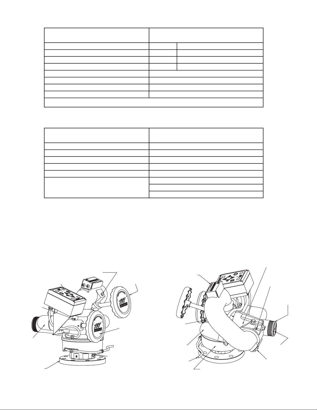
The Hurricane RC Monitor as shown in Figure 3.2 along with the names of some various parts and controls.
CONTROL STATION BOX
WITH CONTROL BUTTONS
(SEE SECT. 6.2.1.1)
GREASE ZERK
(SECT. 8.1)
HORIZONTAL
MOTOR (SECT. 9.3)
INLET
(FIGURE 3.3)
PORT FOR
PRESSURE GAGE
(SECT. 4.5)
ELEVATION
HANDWHEEL
(SECT. 6.1)
HORIZONTAL
ROTATION
HANDWHEEL
(SECT. 6.1)
STRAIGHT BACK
REFERENCE MARK
(SECT. 4.2)
FIG 3.2
Part Identification
PRODUCT NAME LABEL
WITH
SERIAL# & MODEL #
HORIZONTAL
ROTATION TRAVEL
STOPS 5 PLACES
(SECT. 4.4)
ELEVATION
MOTOR (SECT. 9.3)
POWER CABLE
WIRE SKIRT/CABLE GUIDE
(SECT. 9.1)
ELEVATION DRIVE
HOUSING
(SECT. 9.2)
GREASE ZERK
(SECT. 8.1)
OUTLET
(FIGURE 3.3)
BUILT IN
STREAM
STRAIGHTENER
AUTOMATIC
DRAIN
(SECT. 4.6 & 6.4)
4
Page 5
3.3 INLETS AND OUTLETS
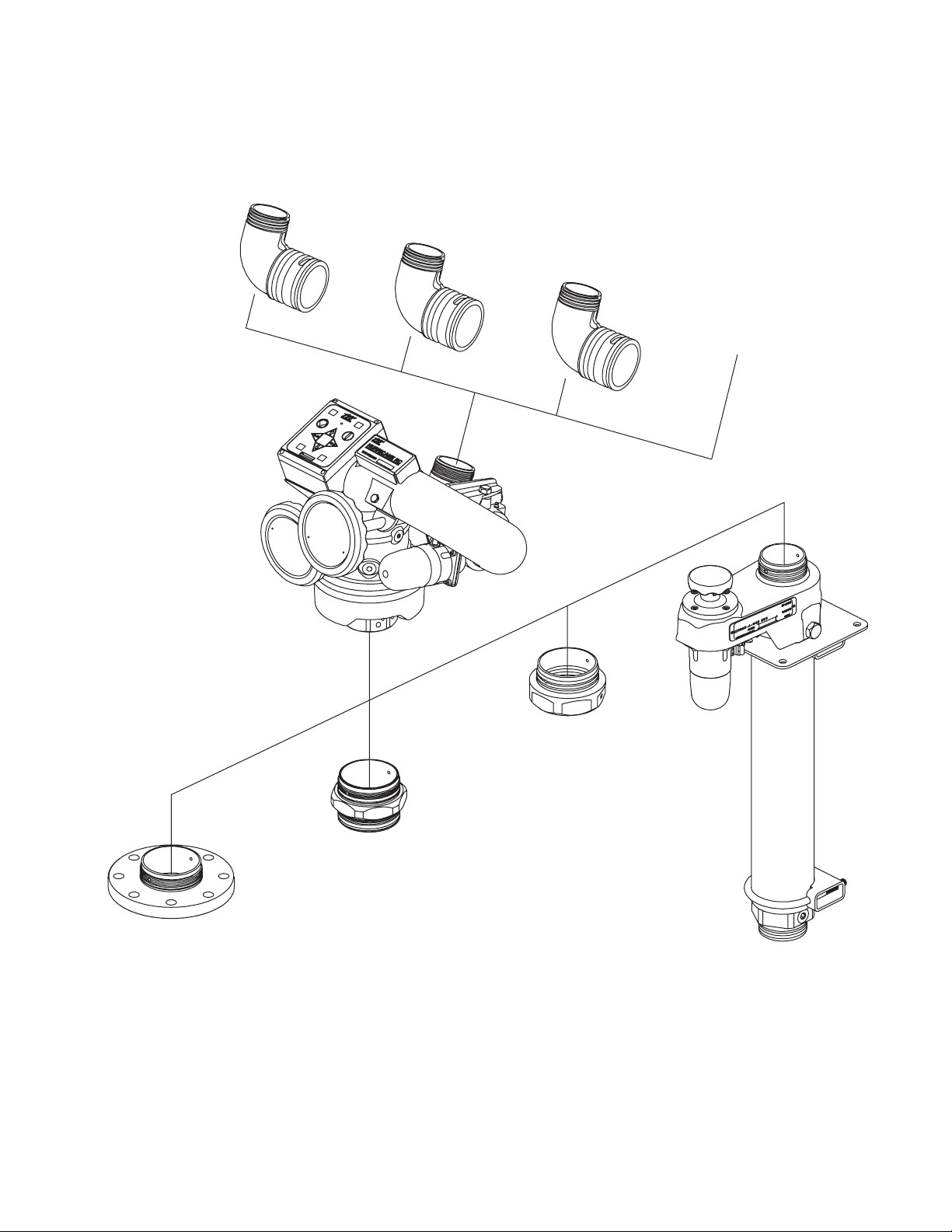
The standard Hurricane RC Monitor inlet is CODE-RLF for direct connection to TFT's Extend-A-Gun RC3. Monitor inlet CODE-RPF is
available for direct connection to Extend-A-Gun RC4. The standard outlet is 2-½”-6 National Hose male. Various other inlet and oputlet
fittings are available as shown in Figure 3.3.
2.5"-7.5 NH
(65mm) MALE
2.5"-11 BSP
(65mm) MALE
2.5"-11.5 NPSH
(65mm) MALE
SPECIAL
THREADS
CODE-RLF FEMALE
or
CODE-RPF FEMALE
3.0"ANSI 150 (Y4410A)
or
4.0"ANSI 150 (Y4415A)
or
DN80, PN16 (Y4423A)
or
DN100, PN16 (Y4425A)
FLANGE
3.0" NPT FEMALE (Y4440NL)
or
4.0" NPT FEMALE (Y4450NP)
3.0"BSP MALE (Y4420A)
or
4.0"BSP MALE (Y4430A)
EXTEND-A-GUN RC3
or
EXTEND-A-GUN RC4
FIG 3.3
Inlets And Outlets
5
Page 6
3.3.1 INLET FLANGE SIZE SPECIFICATIONS
MODEL FITS FLANGE OUTSIDE THICKNESS BOLT HOLE
DIAMETER CIRCLE
XFIH-E1*A 3” ANSI 125/150 7.5” .75" 6.0" 4 5/8" 76-80 FT-LBF
(metric DN8 PN20) 190mm 20mm 152.5mm 4 M16 100-110 Newton Meters
XFIH-E2*A 4" ANSI 150 9.0" .94" 7.5" 8 5/8"
(metric DN100 PN20) 230mm 23mm 190.2mm 8 M16 100-110 Newton Meters
XFIH-E4*A metric DN80, PN16 200 mm 22 mm 160 mm 8 16 mm 100-110 Newton Meters
XFIH-E5*A metric DN100, PN16 220mm 22 mm 180 mm 8 16 mm 100-110 Newton Meters
NO. BOLT SIZE OF TORQUE ON BOLTS
HOLES BOLTS
76-80 FT-LBF
* The second to last digit in the model number refers to exit thread size and type.
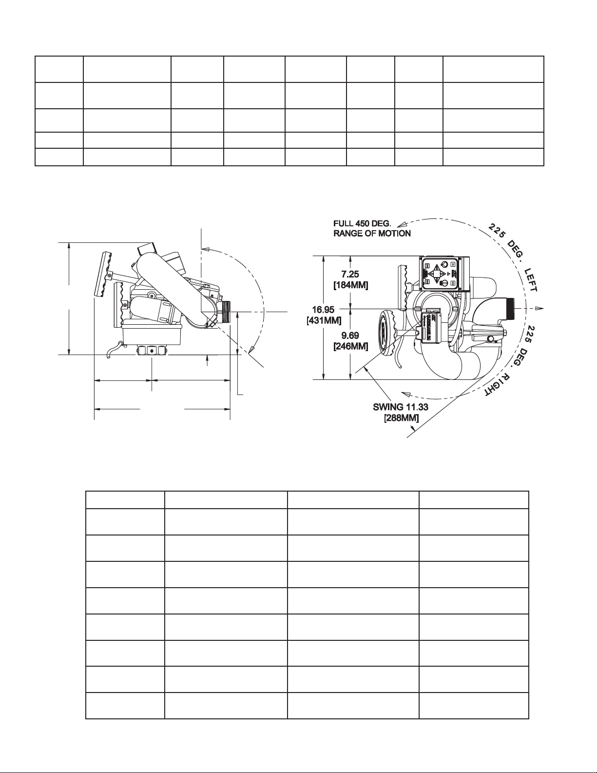
3.4 OVERALL DIMENSIONS
9
0
A
E
R
B
T
I
D
O
C
A
V
L
E
R
A
N
G
E
O
F
M
O
T
I
O
N
5.89
[150MM]
FIG 3.4
Overall Dimensions
E
G
.
4
B
5
E
L
O
D
W
E
G
.
15.43
[392MM]
SHOWN
WITHOUT
INLET FITTING
(SEE TABLE
IN SECT. 3.4.1
FOR
ADDITIONAL
HEIGHTS)
7.90
[201MM]
V
3.64
[93MM]
10.74
[273MM]
18.64
[473MM]
3.4.1 OVERALL HEIGHT INCREASE FOR INLET FITTINGS
MODEL INLET FITTING TYPE ADDITIONAL HEIGHT OVERALL HEIGHT
XFIH-E1*A
XFIH-E2*A
XFIH-E4*A
XFIH-E5*A
XFIH-E6*A
XFIH-E7*A
XFIH-E8*A
XFIH-E9*A
* The second to last digit in the model number refers to exit thread size and type.
3” ANSI 125/150 .75” 16.18”
(metric DN8 PN20) 20 mm 412 mm
4” ANSI 150 .94” 16.37”
(metric DN100 PN20) 23 mm 415 mm
metric DN80, PN16 2.80” 18.23”
22 mm 414 mm
metric DN100, PN16 2.80” 18.23”
22 mm 414 mm
3” NPT Female 2.00” 14.43”
51 mm 443 mm
4” NPT Female 1.75” 17.18”
45 mm 436 mm
3” BSP Male 2.30” 17.73”
58 mm 450 mm
4” BSP Male 2.30” 17.73”
58 mm 450 mm
6
Page 7

3.5 ELECTRICAL CONTROLS
The electric Hurricane RC monitor is controlled by a very powerful, state-of-the-art electronics system. The key components of the
system are the motor control boards and a communication board. Each motor control board has its own microprocessor and a
sophisticated motor control chip. The communication board also has a microprocessor, which handles the interface to the operator
stations. All the components on these boards are solid state; there are no relays or electro-mechanical devices to wear out over time.
The hardware and software have been designed withseveral key features:
3.5.1 MOTOR CONTROL BOARD (MCB) AUTO CONFIGURE
Each monitor has three MCBs, one for each motor, which controls motor movement and direction for horizontal rotation, elevation, and
nozzle pattern. In the unlikely event of a MCB failure, the failed board can be removed and one of the other two remaining MCBs can be
moved into that position. This MCB will then auto configure itself to take over the control of that axis, so that the monitor can continue to
be used, with two of the three motors. This is also ahelpful benefit when troubleshooting and requires fewer spare parts to bestocked.
3.5.2 MOTOR CURRENT LIMITING
The microprocessor on theMCB continuously monitors the motor current.As the motor reachesan endstop orif there is an obstruction,
the motor current rises very quickly and the motor controlchip automatically shuts down the motor in a fewmilliseconds. This eliminates
the need for any type of external limitswitches and the associatedwiring. The microprocessor also locks the operatorfrom moving in the
stopped direction again, until the operator first moves in the opposite direction.
3.5.3 MOTOR SOFT STOPS
The horizontal and vertical motors are equipped with feedback encoders, which allow the microprocessor to know the motor position at
all times. The first time a motor reaches an end stop or strikes an obstruction, the microprocessor sets a new soft stop position just
before the end stop. From that point on, when the axis approaches the stop, the MCB automatically slows down the motor until the end
stop is reached. This significantly reduces thewear on the motor, gearbox, andexternal gears.
3.5.4 MOTOR SLOW/FAST SPEED
When an operator presses one of the buttons, the associated motor starts in slow speed mode so that the operator can accurately
control the water stream. After approximately 1-2 seconds the motor automatically ramps up to a fast speed, for quickly moving into
position. When quickly changing directions, monitor retains speed from prior move. If low speed is selected, monitor does not ramp to
high speed but remains in slow speed.
3.5.5 COMMUNICATION PROTOCOL
The communication from the monitor to the operator stations is performed over two wires using RS-485 serial protocol. Multiple
operator stations can be added withonly two wires for power and two wires for the RS-485 protocol between each station.
3.5.6 OSCILLATE AND STOW FEATURES
The OSCILLATE feature allows the user to program up to 65 points of continuous movement of the horizontal and vertical axes. The
OSCILLATEpattern can be programmed from any operator station that has the OSCbutton.
The STOW feature allows the user to move the monitor, with one touch of a button, to a safe position before moving the fire truck. The
monitor will always move to two end stops to verify the correct position. During the programming procedure, the user has the ability to
select which axis moves first. This is helpful to avoid lights, hoses, obstructions, etc. The user can program up to 10 points of movement
to reach the final STOW position. TheSTOW pattern can be programmed from any operator station that has the STOW button.
See section 6.2.3 and 6.2.4 for programming instructions.
4.0 INSTALLATION
4.1 STRUCTURAL REQUIREMENTS
FOR MONITOR MOUNTING
The structure that the Hurricane RC Monitor is mounted to must
withstand the internal pressure of the monitor as well as shear and
bending forces due to nozzle reaction. Nozzle reaction can be as
high as 1,050 lbs (480 kg) (1250 gpm at 200 psi).
For flanged connections, the use of flat flanges without raised faces
is recommended. Use a full-face gasket as defined in SME 16.21 or
ISO 7483. Tighten flange bolts in an alternating sequence as shown
in figure 4.1. Tighten to 76-80 ft-lb (100-110Newton-Meters).
3 4
1
1
5
3
7
2
FIG 4.1 - Flange Bolt Tightening Sequence
Tighten sequentially each bolt three times.
2
8
6
4
WARNING
Injury can result from an inadequately supported monitor. The monitor mount must be capable of
supporting the nozzle reaction force which can be as high as 1500 lbs (700 kg). Flanges and pipe
made from plastic are inadequate for monitor mounting and must not be used. This monitor is not
recommended for portable use.
7
Page 8
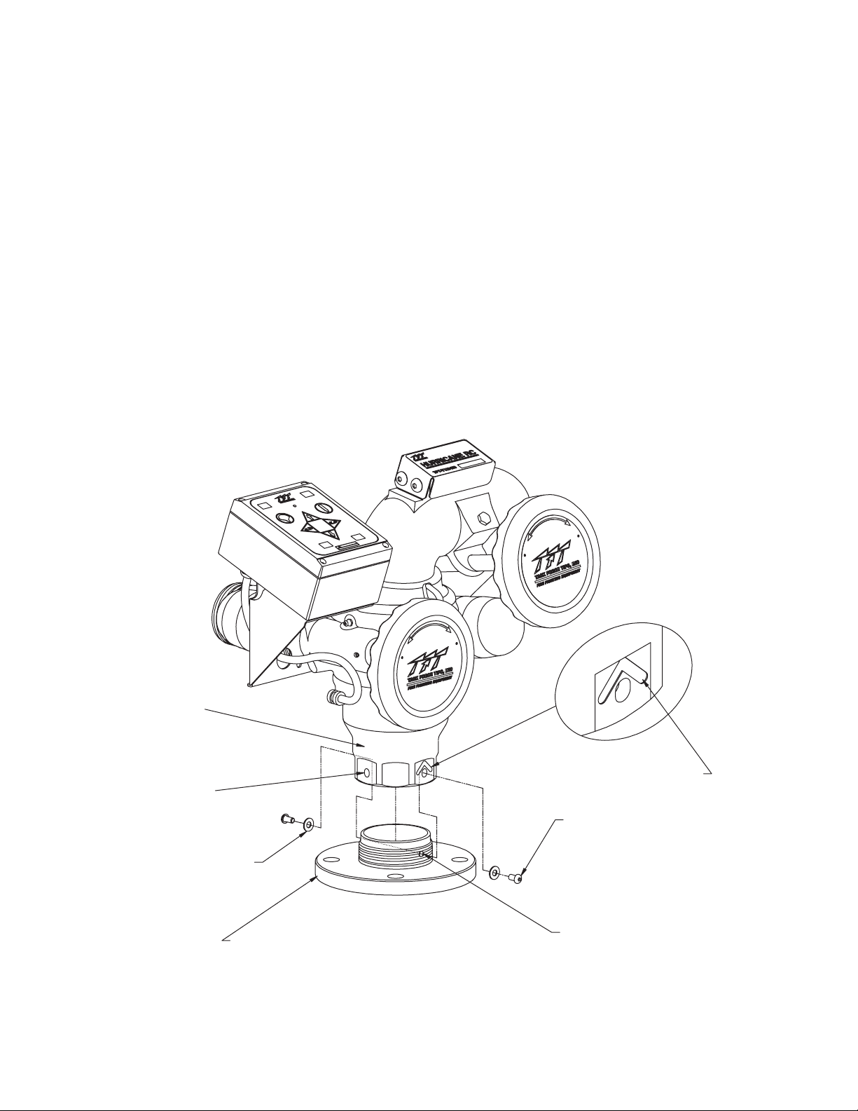
4.2 INLET FITTINGS OR EXTEND-A-GUN RC INSTALLATION
The Hurricane RC Monitor is available with various inlet fittings as shown in figure 3.3. The Hurricane RC Monitor also connects directly
to TFT's Extend-A-Gun RC3 or RC4.The fittings andExtend-A-Gun RCare attached to the monitorby meansof athreaded jointwith an
o-ring seal. Once in the proper orientation, the threaded joint is locked from rotation by two ¼-28 button head cap screws as shown in
figure 4.2A. This makes for easy removal of the monitor, since the large threads of the joint are not tightened and do not have any thread
locking compounds on them. It is best to install the inlet fitting or Extend-A-Gun RC to the apparatus and than install the monitor to the
inlet fitting or Extend-A-Gun RC. This gives more room to install the bolts in the case of flanged fittings. Referring to figures 4.2A and
4.2B, the installation sequence is as follows:
1) Install inlet adapter or Extend-A-Gun RC to apparatus.
• Mount so that 180 degree apart threaded cross holes will give desired direction relative to the “Straight Back Reference Mark”
when the monitor is installed.
2) Screw monitoronto inlet adapter or Extend-A-Gun RC until threaded joint bottoms out.
• Do not use pipe dope or Loctite on the inlet base threads. These threads are sealed with an o-ring. The use of thread locking
compounds will make removal difficult.
3) Unscrew monitor slightly until a pair of 90 degrees apart slots line up with the 180 degrees apart threaded cross holes in the inlet
adapter or Extend-A-Gun RC.
• Orient monitorso that the Straight Back ReferenceMark is facing the desired direction.
• Slots will line up with threaded cross holes every 90 degrees of rotation.
• Monitor maybe unscrewed up to one full turn from the bottomed out position.
4) Install ¼-28 by ½ long button head cap screws and washers in the two threaded crossholes.
INLET BASE
90 DEGREE
APART SLOTS
WASHER 2 PLACES
(TFT# VW687X281-50)
(This view shown without power cable guide for purposes of illustration.)
INLET FITTING MOUNTED TO APARATUS
3.0" ANSI 150 SHOWN, OTHERS SIMILAR
FIG 4.2A
3” Inlet Fitting Connection
8
STRAIGHT BACK
REFERENCE MARK
1/4-28 X 1/2LONG
BUTTON HEAD
CAP SCREW
2 PLACES
(TFT# VT25Y28BH504)
180 DEGREE APART
THREADED HOLES
Page 9
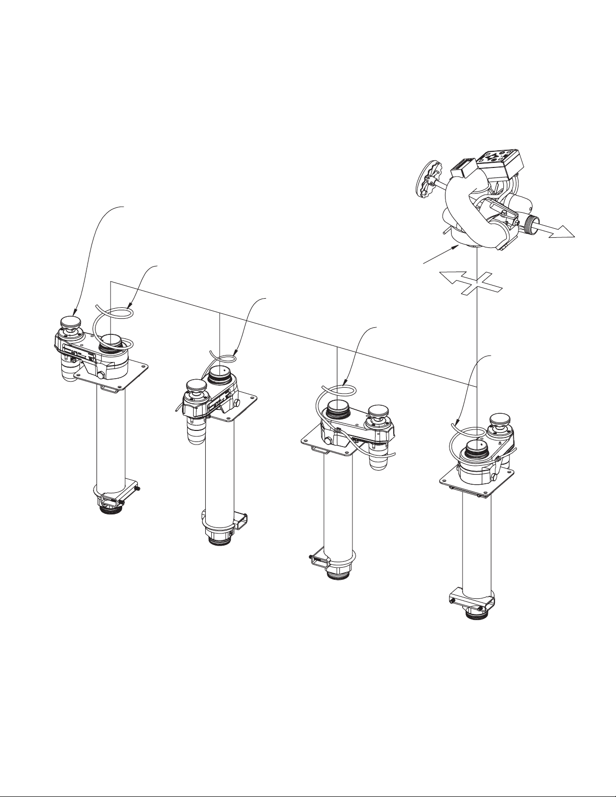
The Extend-A-Gun RC manual override knob may be mounted
in any one of four possible orientations (90 degrees apart).
MANUAL OVERRIDE
KNOB ON
EXTEND-A-GUN
1-1/2 TURNS
APPROX. 37 IN.
3/4 TURNS
APPROX. 33 IN.
STRAIGHT BACK
REFERENCE MARK
(SEE FIGURE 4.2A)
1 TURN
APPROX. 33 IN.
1-1/4 TURNS
APPROX. 34 IN.
FIG 4.2B
Possible Extend-A-Gun RC Mounting Orientations
The Extend-A-Gun manualoverride knob may be mounted in any of four possible orientations (90degrees apart) relative to the Straight
Ahead Reference Mark on the monitor.
NOTE: Hurricane RC monitor, for use with Extend-A-Gun RC, comes with the wire installed in a nylon tube. The nylon tubing gives the
wire additional stiffness so it better follows as the Extend-A-Gun RC extends or retracts. A fitting is also supplied and is to be used where
the nylon tubing and wire pass though the deck.
9
Page 10
4.3 NOZZLE CONNECTION
The Hurricane RCmonitor outlet thread types are as shown in figure 3.3.The nozzle is simply screwed onto the Hurricane RC monitor's
exit threads. Insure that the nozzle's coupling does not make contact with the elevation drive housing when the monitor is in its highest
elevation position.
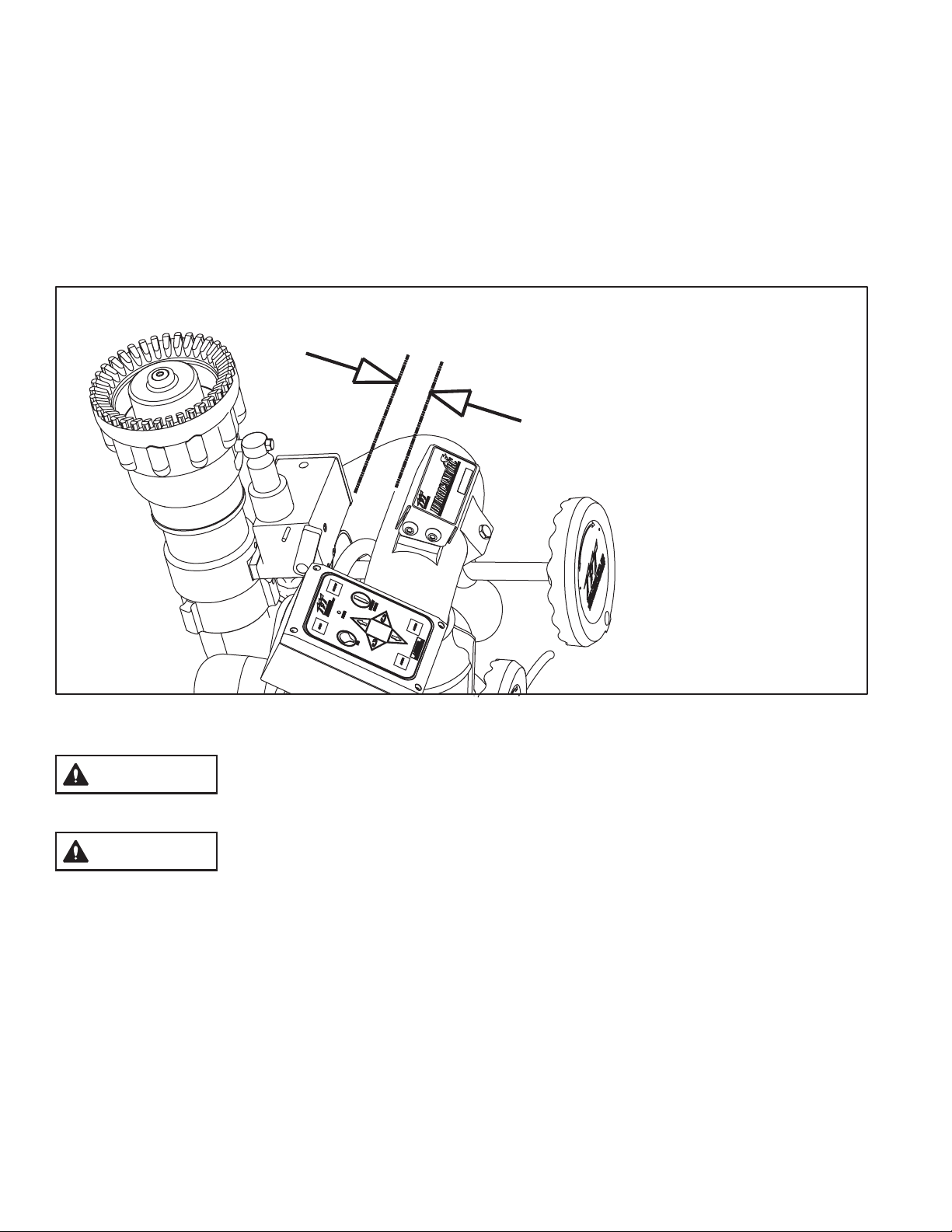
For nozzles with electric pattern control, a waterproof connector wire is provided at the bottom outlet of the Hurricane RC's control
station box. This wire attaches directly to TFT's electric Masterstream 1250 nozzle. The electric actuator box of nozzle must be oriented
to the top side of nozzle for the connection wire to extend 90° above horizontal and 45° below elevation movement. (see figure 4.3 and
refer to Sections 5.12 and 6.6.2 for properly attaching female to male connectors). Any other nozzle should have the corresponding
male electrical connector installed and long enough wire to extend of the
nozzle.
AND MUST REMAIN ON TO MAINTAIN THE WATER TIGHTNESS OF THE ELECTRICAL SYSTEM.
DO NOT CUT OFF THE FEMALE CONNECTOR ON THE MONITOR. THIS CONNECTOR IS MOLDED ONTO THE WIRE
90° above horizontal and 45° below elevation movement
CAUTION:
TFT's Master Stream 1250 ER Nozzle
Electric Actuator Box must be on the Top
Side for its Edge to line up with Monitor
Waterway Top Body as shown.
FIG 4.3
Correct ER Nozzle Install Orientation
The nozzle threads must match the threads on the Hurricane RC in both size and type.
CAUTION
CAUTION
Mismatched or damaged threads may cause the nozzle to leak or uncouple under pressure and
could cause injury.
Do not connect aluminum to brass or brass to aluminum. Dissimilar metals coupled together can
cause galvanic corrosion that will freeze the threaded joint or cause complete loss of thread
engagement. If dissimilar metals must be coupled together, the effects of corrosion can be greatly
delayed by various coatings on the metal such aspowder paint, hard anodizing or silicone grease.
4.4 HORIZONTAL ROTATION TRAVEL STOPS
The range of Horizontal (left-right) travel for the Hurricane RC monitor is limited to 450 degrees or 225 degrees from either side of a
nozzle discharge position. Horizontal (left-right) travel stop bolts may be installed in the monitorto limit travel asshown in figure 4.4Aand
4.4B. Note that left and right are relative to the “Straight Back Reference Mark” shown in figure 4.4A, and refer to the operator's position
behind the monitor, opposite the nozzle's discharge direction. Also, Figure 4.4A shows the range of travel for the various stop bolt
locations along with installation notes as shown inFigure 4.4B.
10
Page 11
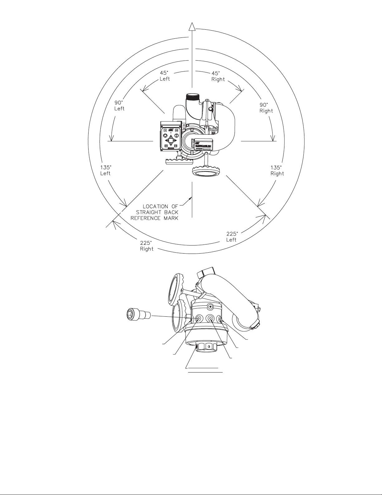
Pry out plastic plug and
install Stop Bolt(s)
to obtain desired
travel limits.
(TFT# Y4145)
FIG 4.4A
Horizontal Travel Limits
45° RIGHT
90° RIGHT
FIG 4.4B
Horizontal Travel Stop Bolt Locations
STRAIGHT BACK
REFERENCE MARK
45° LEFT
90° LEFT
135° LEFT AND RIGHT
(ONLY ONE STOP BOLT
NEEDED FOR THIS
TRAVEL LIMIT)
4.5 PRESSURE GAUGE PORT
There is a ¼” NPT female threaded hole located behind the elevation hand wheel for the installation of a pressure gauge if desired. This
hole has a pipe pluginstalled from the factory. Unscrewthe pipe plugand install the gauge using pipesealant. Make sure that thegauge
does not interfere with the handwheel.
4.6 AUTOMATIC DRAIN
There is an automatic drain on the Hurricane RC installed from factory, that will empty the water from the low point of the lower bend to
prevent freezing (Figure 3.2). This valve will close automatically when the internal pressure in the monitor reaches approximately 5 psi
(0.34 bar) and will reopen again when the pressure drops to this point. Refer to Section 6.4 for disabling the automatic drain if desired.
Asecondary drain valve should be installed on the monitor's inlet piping to drain water in the riser.
11
Page 12
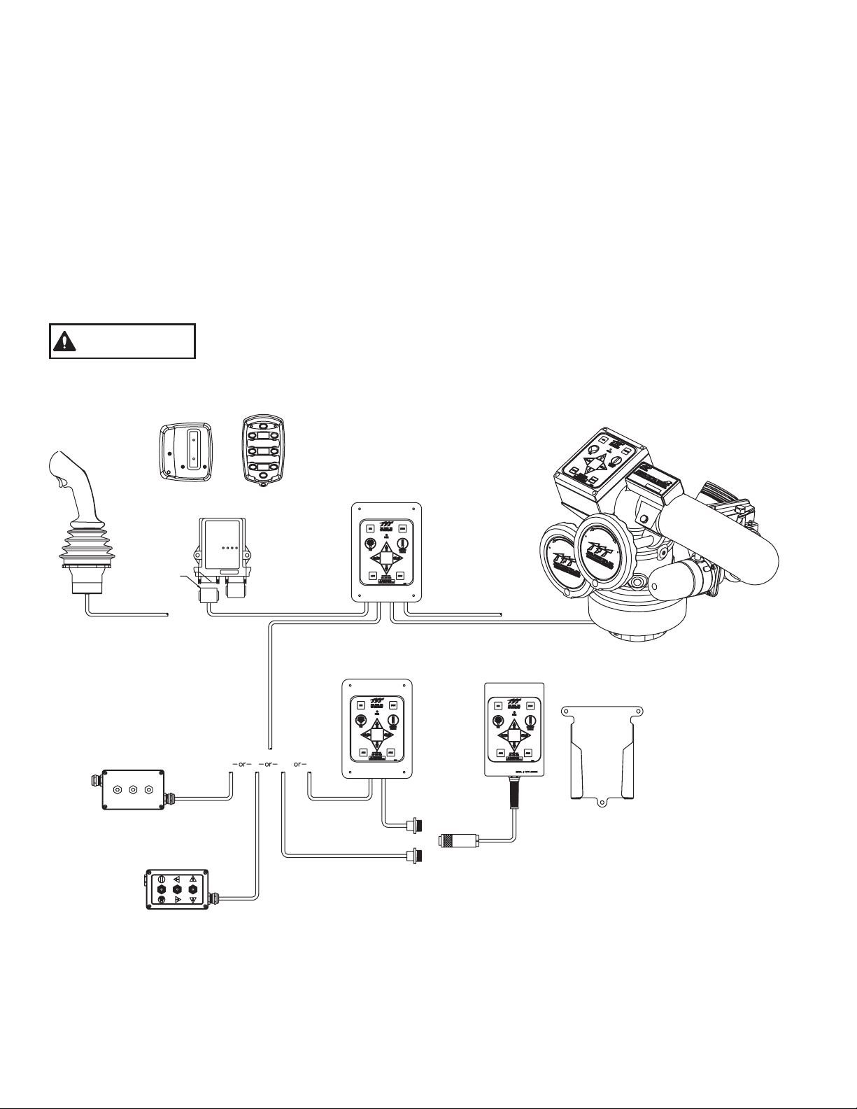
5.0 ELECTRICAL CONTROLS INSTALLATION
The electric RC monitor is supplied with a monitor mounted operator station. The wiring on the monitor and for this operator station is
factory installed. The assembly is supplied with a 30-foot length of cable for connection to the operator control stations as shown in
Figure 5.0 or directly to a protected voltage supply. This cable has 4-conductors which supply power and the communications from the
operator stations to the monitor. To complete the installation, the installer will need to mount and wire the selected operator stations.The
power supply for the monitor will need to be connected to a protected circuit from the truck's power distribution center. Refer to the
specifications section 3.2.1 for nominal current draw.
!
Good mechanical connections on the wires are absolutely necessary and should be checked periodically. Poor electrical
connections can cause power loss to the electric RC monitor and be a fire hazard.
!
Careful selection of wiring is critical to avoid excessive voltage drop.
!
Be careful to route cables in a protected area away from high heat sources.
!
Use grommets whenever wires pass through holes to prevent damage due to snags, abrasions, etc.
!
Secure cables close to control box with plastic wire ties or cable clamps to relieve stress on the cables.
!
Disconnect power before installing or servicing the electrical components. The RC monitor control boxes and motors are not rated
as ignition proof, explosion proof, or intrinsically safe.
The electric motors and other components are ignition sources. The electric drives should be
WARNING
Charging Cradle
Joystick Operator
Station Sec 5.5
operated only in areas where there is adequate ventilation and no hazard of flammable vapor
buildup.
Wireless Operator
Station Sec 5.4
Monitor Mounted
Operator Station
Deutsch
Connector
7/C-20
Communication
Interface Box Sec 5.7
Toggle Switch
Operator Station Sec 5.6
Recommended Tool List
Receiver
9/C-20
2/C-14, 2/C-20
Primary Operator
Station Sec 5.1
2/C-14 * See Note
10 ft (3m) Maximum
Optional Operator
Station Sec 5.2
30 or 100 ft
(9 or 27m)
FIG 5.0
Electrical Components
(non-aerial installation)
Power
2/C-14, 2/C-20
30 ft (9m) Maximum
Tether Operator
Station Sec 5.3
NOTE: To avoid excessive voltage
drop at monitor operator station, do
not lengthen factory supplied power
or monitor cable.
Voltage supplied to PRIMARY
OPERATOR STATION should not fall
below 13 volts when monitor is in
operation.
11/32” nut driver 20mm open-end box wrench
17mm open-end box wrench
Terminal crimping tool
Utility knife
5/32” drill bit
25/32” drill bit
12
#2 Phillips screwdriver
Small flat blade screwdriverWire cutter/stripper
Page 13
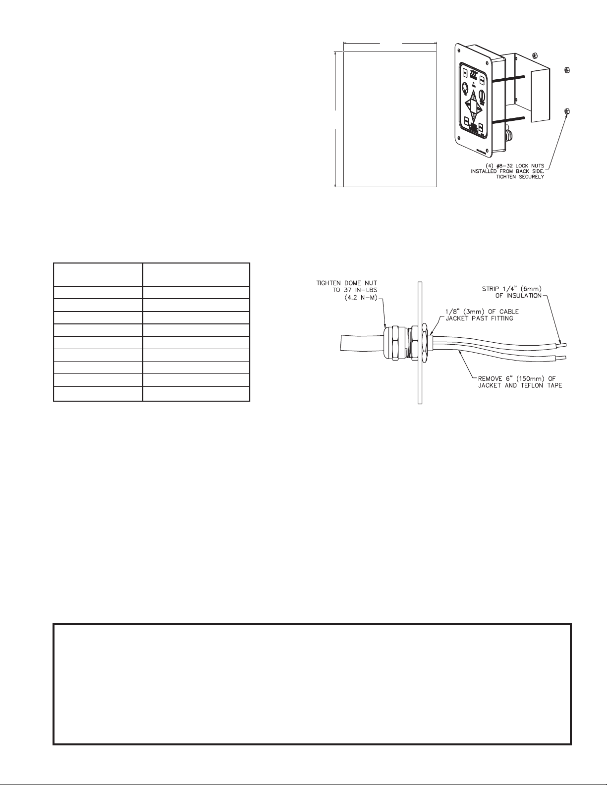
5.1 PRIMARY MONITOR OPERATOR STATION
This operator station will include the wiring connections for the
cable from the monitor and the incoming power. In many
installations this operator station will also include the wiring
connections for the wireless, joystick, ortether operator station. The
enclosure is designed to be recess mounted in a panel.
5-1/8
(130 mm)
5.1.1 MOUNTING
7-7/16
(190 mm)
Select proper operator location. Panel space required willbe 5-5/8”
x 8” (142 x 200mm). A depth of 3-1/2” (89mm) will be required
behind the panel. Additional space will be required where the
cables exit the back of the enclosure. Refer to Figure 5.1.1 for
cutout dimensions.
Primary & Optional Operator Stations Cutout Dimensions
Fig 5.1.1
5.1.2 ELECTRICAL WIRING
After selecting and mounting the desired operator stations, refer to Figures 5.1.2B-E for wiring connections. Refer to Figure 5.1.2A for
typical cable preparation. Be sure to tightenall terminal block screws securely.
Receiver Cable Termination Point In
Wire Color Operator Station
RED RED (+)
BLACK BLACK (-)
GREEN/BLACK UP
WHITE/BLACK DOWN
WHITE LEFT
ORANGE/BLACK RIGHT
BLUE FOG
ORANGE STRAIGHT STREAM
GREEN NOT USED (CUT)
Fig 5.1.2
Wireless Operator Station
Wiring Color Code
NOTE: CABLE IS GEL FILLED TO
PREVENT MOISTURE WICKING
INTO ENCLOSURE. GEL IS NONHAZARDOUS AND SHOULD BE
WIPED OFF CONDUCTORS
WITH RAG.
Typical Cable Preparation
Fig 5.1.2A
FROM/TO MONITOR OROPERATORSTATION
Refer to Figure 5.1.2B for connections.
FROM/TO TETHER OR OPT. STATION
OPERATOR
Remove rubber plug in hole labeled WIRELESS OPER. STATION and discard. Refer to Figure 5.1.2C for connections.
WIRELESS STATION
OPERATOR
Plug end of cable with Deutsch connector into gray receptacle on receiver. Make sure connector snaps into place.
Remove rubber plug in hole labeled WIRELESS OPER. STATION and discard.
Refer to Figure 5.1.2D for connections. Refer toFigure 5.1.2 for wire color designations.
MAIN POWER CONNECTION TO TRUCK
Route cable and connect to a protected circuit from the truck’s power distribution center. Connect the red wire to positive and
the black wire to negative (ground). Refer to Figure 5.1.2E for connections.
IMPORTANT!!
When mechanical installation and electrical connections are complete, perform the following test to verify voltage supply is adequate
and the current limiting feature is functioning.
1) Apply powerto monitor control box.
2) Press LEFTor RIGHT button and hold untilmonitor reaches its stop position. Continue tohold button down.
3) Once movement is stopped, manually turn override knob in opposite direction while continuing to hold button down. If knob
can be turned, then voltage supply is adequate. If knob cannot be turned and motor continues to operate, then the voltage
supply or wiring is not adequate. Check connections and voltage connection point, rewire if necessary. NOTE: Override
knob will only turn in one direction.
13
Page 14
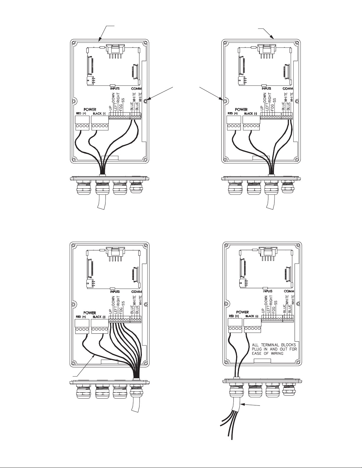
VERIFY RUBBER SEAL IS CLEAN AND UNDAMAGED.
VERIFY THAT NO WIRES ARE CAUGHT BETWEEN LID AND BOX.
USE SUPPLIED FLAT HEAD
SCREWS WITH O-RING SEALS.
TIGHTEN SCREWS SECURELY.
(6) PLACES.
FIG 5.1.2B
From/To Monitor Or Operator Station Connections
WIRELESS
STATION ONLY
FIG 5.1.2C
From/To Tether, Optional Operator Station
Toggle Switch Operator Station,
or Communication Interface Box.
WIRELESS OPERATOR STATION.
JOYSTICK OR INSTALLER SUPPLIED SWITCHES.
SEE SECTION 5.1.2 FOR TABLE DEPICTING
WIRELESS RECEIVER COLOR CODE.
FIG 5.1.2D
Wireless Operator Station Connections
14
BLUE AND WHITE
NOT USED
10 FT. (3M) MAXIMUM LENGTH
RED AND BLACK
TO POWER DISTRIBUTION CENTER
FIG 5.1.2E
Main Power Connections
Page 15
5.2 OPTIONAL MONITOR OPERATOR STATIONS
The electronic package for the Hurricane RC is designed for multiple operator stations. The operator stations use an RS-485
communication design and the communication boards in each station are connected in series. This gives the flexibility to choose more
than one location on a truck to operate the monitor.To install multiple operator stations, complete the following instructions in this section
and repeat for each additional station. The enclosureis designed to be recess mounted in a panel.
5.2.1 MOUNTING
See section 5.1.1
5.2.2 ELECTRICAL WIRING
See section 5.1.2
5.3 TETHER MONITOR OPERATOR STATION
This operator station will have a factory installed 4-conductor cable, which will act as a tether, with a plug on the end. The installer will
need to mount the holster and receptacle. Since the communication boards are connected in series, the receptacle for the tether
operator station needs to be wired into the last primary or optional operator station (if multiple recessed operator stations are installed,
refer to section 5.2).
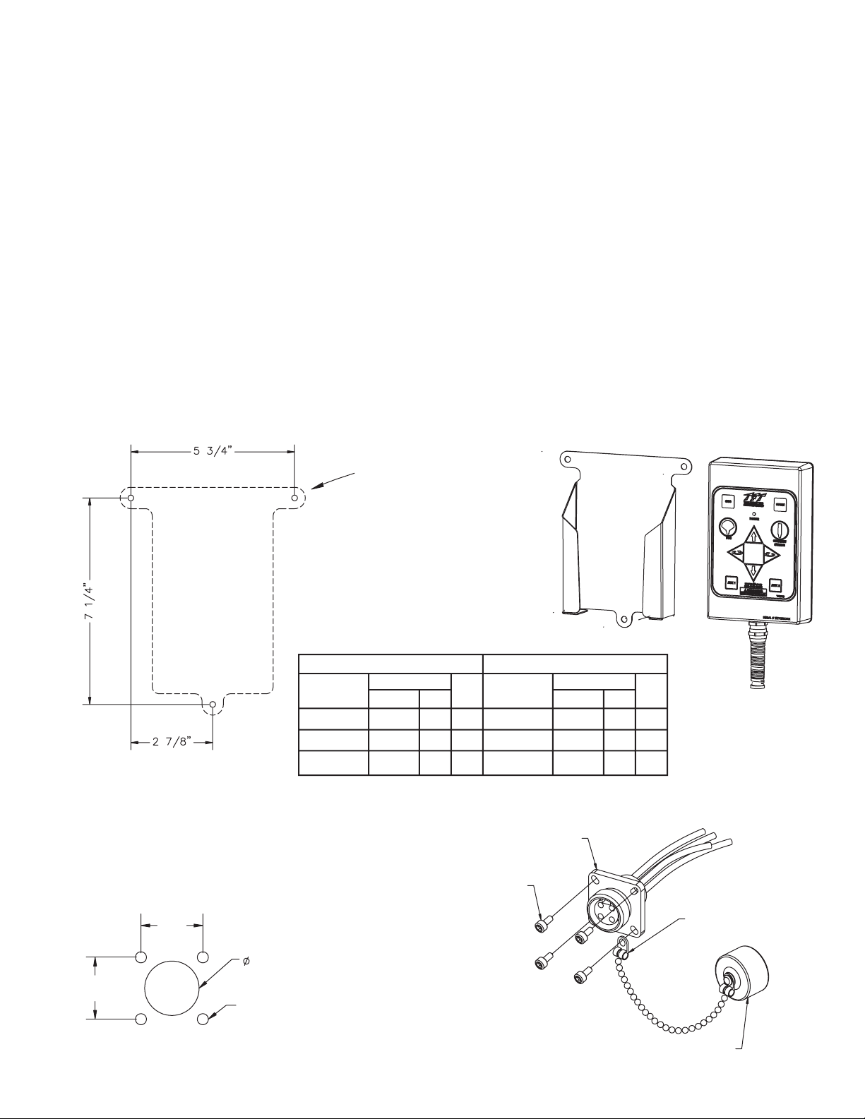
The holster is supplied with(3) 1/4-20 stainless steel self-tapping screws. Make sure the material beneath the bracket is substantial and
thick enough to hold self-tapping screws. Make sure the area on the back side of the mounting surface is clear of obstructions. We
recommend a minimum thickness of 3/32" (.093" - 2.4 mm) in aluminum and 5/64 (.078"-2mm) in steel See the chart in Figure 5.3.1 to
determine the correct pilot hole size.
5.3.1 HOLSTER MOUNTING
Select proper location for mounting holster, preferably inside a storage compartment. Panel space required will be 6.5” x 8.0” (165 x
203mm). Refer toFigure 5.3.1for hole dimensions. Holster can be used as template.
(146 mm)
Drill (3) Pilot Holes
(refer to hole size chart)
Mount Holster With (3)
1/4-20 Self-Tapping Screws.
Tighten Securely.
(184 mm)
Hole Size Chart For Self Tapping Screws
ALUMINUM STEEL
Material Use Material Use
Thickness Drill Thickness Drill
Hole Size Hole Size
Inches mm Inches mm
5/64-3/32 .206 5.2 #5 3/32 .213 5.4 #3
1/8 .213 5.4 #3 1/8 .221 5.6 #2
(73 mm)
3/16 .221 5.6 #2 3/16 .228 5.8 #1
Fig 5.3.1 Tether Operator Station Holster Hole Dimensions
5.3.2 RECEPTACLE MOUNTING
Select proper location for mounting receptacle.
Receptacle is 1-1/4” x 1-1/4” and 1/2” deep. (32 mm x 32
mm x 13 mm) Allow extra room behind receptacle for wires.
Refer to Figure 5.3.2 for hole dimensions.
7/8”
(22 mm)
25/32”
(20 mm)
7/8”
(22 mm)
Drill (4) .098” (#40) Holes
Y5310 TETHER RECEPTACLE
MOUNT RECEPTACLE WITH
#4 SELF-TAPPING SCREWS.
TIGHTEN SECURELY.
INSTALL CHAIN CONNECTOR
UNDER SCREW HEAD
HOLE LAYOUT
Fig 5.3.2 Tether Operator Station
Receptacle Hole Dimensions
15
Y5320 CLOSURE CAP
LIX-300 September 15, 2005 Rev04
Page 16
5.3.3 ELECTRICAL WIRING
See section 5.1.2
5.4 WIRELESS MONITOR OPERATOR STATION
This operator station consists of the wireless transmitter, receiver, receiver output cable, and charging cradle. The installer will need to
mount the wireless receiver and wire it into the primary operator station. The charging cradle will need to be mounted in a weatherproof
location and wired to a protected voltage supply.
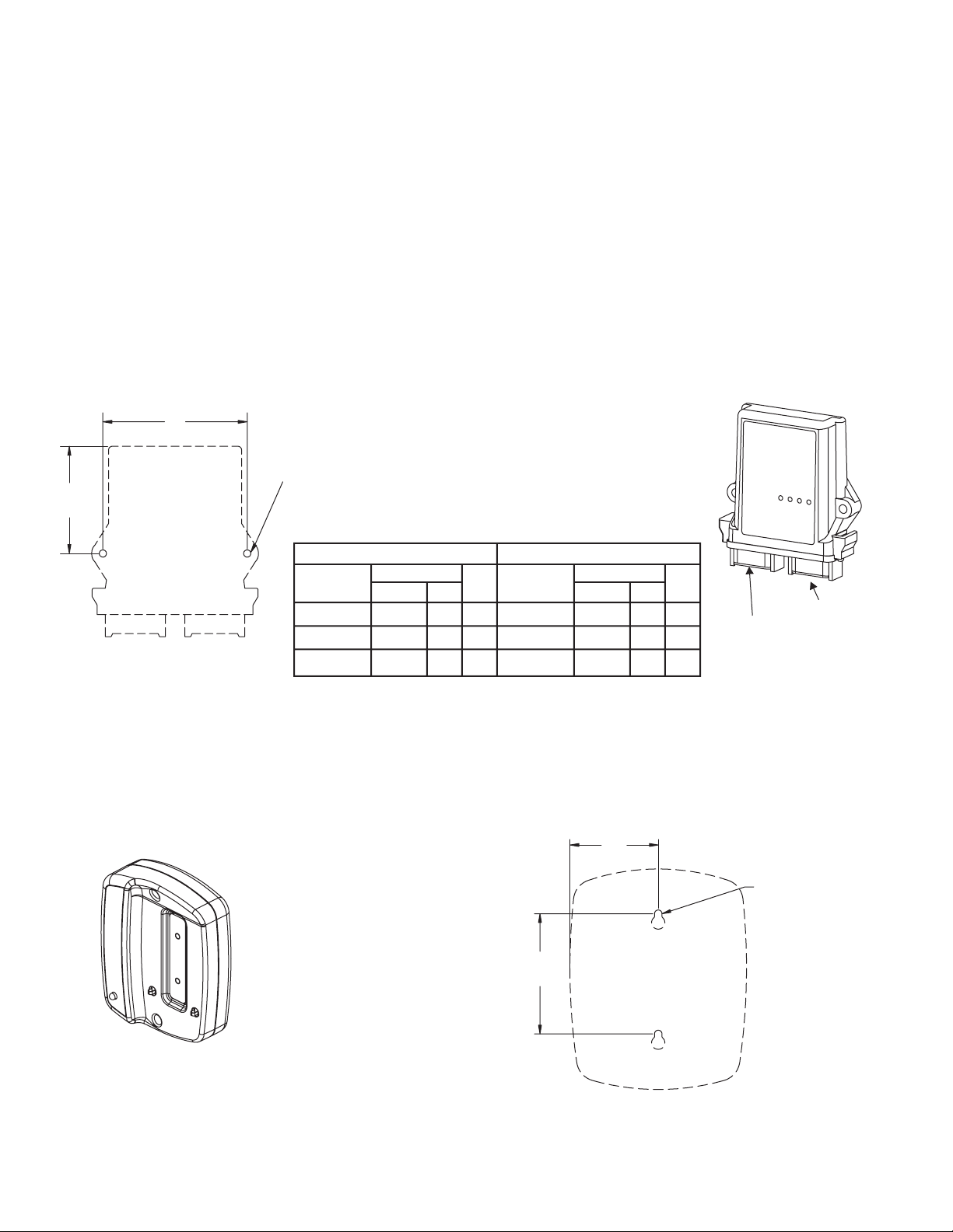
The receiver is supplied with (2) 1/4-20 stainless steel self-tapping screws. Make sure the material beneath the receiver is substantial
and thick enough to hold self-tapping screws. Make sure the area on the back side of the mounting surface is clear of obstructions. We
recommend a minimum thickness of 3/32" (.093" - 2.4 mm) in aluminum and 5/64 (.078"-2mm) in steel. See the chart in Figure 5.4.1 to
determine the correct pilot hole size.
5.4.1 MOUNTING - RECEIVER
Select proper location for mounting receiver. The receiver has a built-in antenna and needs to be in an open area so that it can receive
the wireless signals.A location on the topof the truck is preferable.
range after mounting receiver. Ifrange is inadequate, the receiver may need to be remounted in a more exposed area.
The receiver mustbe mounted so that the supplied 10' (3 m) output cable can be routed back to the primary operator station. Be sureto
mount receiver so that the Deutsch connector is pointing down. Receiver size is 5.1” x 4.0” (130 x 102mm). Refer to Figure 5.4.1for hole
dimensions. Receiver can be used as template.
4”
(102 mm)
3”
(75 mm)
Fig 5.4.1
Wireless Receiver Hole Dimensions
DRILL (2) PILOT HOLES (refer to hole size chart).
MOUNT HOLSTER WITH (2) 1/4-20
SELF-TAPPING SCREWS. TIGHTEN SECURELY.
Hole Size Chart For Self Tapping Screws
ALUMINUM STEEL
Material Use Material Use
Thickness Drill Thickness Drill
5/64-3/32 .206 5.2 #5 3/32 .213 5.4 #3
1/8 .213 5.4 #3 1/8 .221 5.6 #2
3/16 .221 5.6 #2 3/16 .228 5.8 #1
Hole Size Hole Size
Inches mm Inches mm
The optimal operating range is 500' (150 m). Check the operating
PLUG
DEUTSCH
CONNECTOR
5.4.2 ELECTRICAL WIRING - RECEIVER TO THE PRIMARY OPERATOR STATION
See section 5.1.2
5.4.3 MOUNTING CHARGING CRADLE
Select proper location formounting cradle.The cradle isnot weatherproofand needsto beinside a protected location such as in the cab
or a compartment. Cradle size is 4.2” x 4.5”. Refer to Figure 5.4.3for hole dimensions.
2”
(51 mm)
MOUNT CRADLE USING
CUSTOMER SUPPLIED HARDWARE.
TIGHTEN SECURELY.
2-3/4”
(70 mm)
Fig 5.4.3
Charging Cradle Hole Dimensions
DRILL (2)
PILOT HOLES
FOR #8
FASTENER
5.4.4 ELECTRICAL WIRING CHARGING CRADLE
Use two (2) ¼” spade lugs to connect power to the cradle from a protected voltage supply from the truck’s power distribution center.
Connect the positive lead to the terminal marked CHARGE BATT and the negative (ground) lead to the terminal marked GROUND. Do
not make connections to any other terminals. The circuit from the truck power distribution center should be energized continuously to
keep the transmitter fully charged.
16
Page 17
5.5 JOYSTICK MONITOR OPERATOR STATION
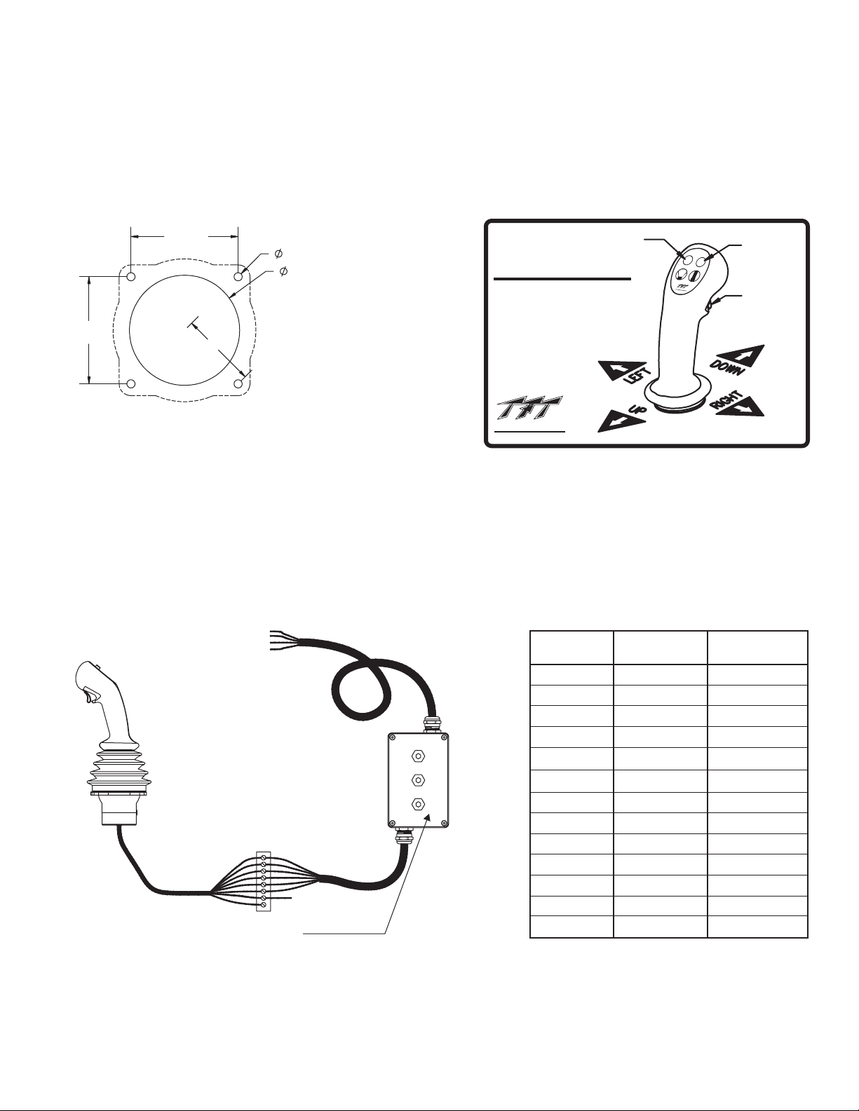
This operator station allows the monitor to be controlled by a joystick. The installer will need to mount the joystick and connect the
cables to the communication interface box or to a primary operator station. The joystick needs to be mounted in a weatherproof
location. Example: Inside the cab of the truck.
5.5.1 MOUNTING
Select proper weatherproof operating location. Joystick will require 4 ½”x4½”(114x114mm) of panel space. A depth of 4”
(100mm) will be required behind the panel. Refer to Figure 5.5.1.1 for hole dimensions.
After mounting, the installer may rotate the joystick up to 22 degrees in either direction. To rotate joystick, lift the rubber boot to
expose adjustable clamp. Loosen the clamping screws, rotate the joystick to desired position, and tighten clamping screws.
2-27/32
(72 mm)
1/4(6mm)
3 (76 mm)
SMART SHAPER
1)2)NOZZLE STOPS AT FULL FOG
FOG THEN FLUSH
PRESS AGAIN FOR FLUSH
www.tft.com
FOG
STRAIGHT
®
TA
S
K
F
O
R
C
E
T
IP
S
F
IR
E
F
I
G
H
TI
N
G
EQ
U
I
P
M
E
N
T
STRAIGHT
STREAM
AUX
FUNCTION
2-27/32
(72 mm)
(51 mm)
2
HOLE MOUNTING DETAIL
Fig 5.5.1.1
Joystick Operator Station
Hole Dimensions
Install joystick instruction
label nearby for quick
operation reference.
®
TASK FORCE TIPS
FIRE FIGHTING EQUIPMENT
800-348-2686 • www.tft.com
Fig 5.5.1.2
Joystick Instruction Label
TRIGGER
5.5.2 ELECTRICAL WIRING
The joystick operator station must be connected to the included Y4E-COMM Communication Interface Box or a separately supplied
Y4E-RP Primary Operator Station. By connecting the joystick to a communication interface box, a primary operator station is not
required and the installer has the option to enable the joystick operator station with the master override feature (see Section 6.2.2).
When a pump panel operator station is being installed, the installer can connect the joystick to the Primary Operator Station, which
will eliminate the need to install the communication interface box.
5.5.2.1 WIRING TO A COMMUNICATION INTERFACE BOX
The joystick cables will be connected to the factory supplied 10' cable from the Communication Interface Box. See figure 5.5.2.1.
POWER AND
COMMUNICATION CABLE
SEE SECTION 5.7.2
**WATER VALVE CONNECTION **
-TRIGGER ACTUATION SWITCHES
ORANGE WIRE TO +12/24 VDC
- 5 AMP SWITCH CONTACT RATING
- WHEN SWITCHING A RELAY OR SOLENOID,
INSTALLA SUPPRESSION DIODE
INSTALLER SUPPLIED
TERMINAL BLOCK OR SPLICES
+12/24 VDC
Y4E-COMM COMMUNICATION INTERFACE BOX
- FACTORY CONFIGURED FOR VOLTAGE INPUTS
- TO CONFIGURE FOR GROUND INPUTS, SEE SEC 5.7.3
Function
UP
DOWN
LEFT
RIGHT
COMMON
STREAM
FOG
TRIGGER
n/u
n/u
n/u
n/u
n/u
Joystick
Cable Color
Grey
Black/White
Ta n
Pink
Red
Blue
Green
Orange
White
Brown
Black
Purple
Yellow
Interface Box
Cable Color
WHITE
BLUE
YELLOW
BROWN
N/A
ORANGE
GREEN
Water Valve**
n/u
n/u
n/u
n/u
n/u
Y5336
Joystick Operator Station Wiring
Fig 5.5.2.1
to Communication Interface Box
NOTE
17
Do not connect 12VDC to Communication Interface Box
wires if configured for GROUND inputs. This will result in
damage to the communication board. See section5.7.3.
Page 18
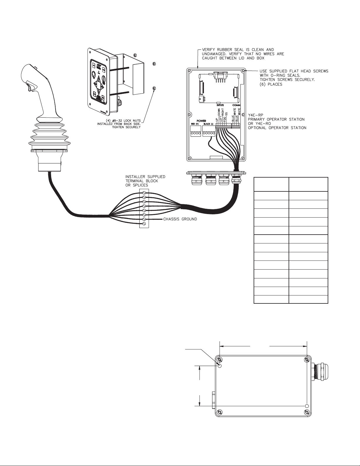
5.5.2.2 WIRING TO A PRIMARY OPERATOR STATION
The joystick cable will enter the primary operator station through the connector labeled WIRELESS OPER. STATION. Refer to
section 5.1.2D.
**WATER VALVE CONNECTION **
-TRIGGER ACTUATION SWITCHES
ORANGE WIRE TO GROUND
- 5 AMP SWITCH CONTACT RATING
- WHEN SWITCHING A RELAY OR SOLENOID,
INSTALLA SUPPRESSION DIODE
Joystick
Cable Color
Grey
Black/White
Ta n
Pink
Red
Blue
Green
Orange
White
Brown
Black
Purple
Yellow
NOTE
Do not connect 12VDC to
Primary Operator Station
inputs. This will result in
damage to the
communication board.
Joystick Operator Station Wiring
INSTALLER SUPPLIED CABLE
O.D. RANGE .16” - .31”
RECOMMEND: 7 CONDUCTOR, 20 AWG,
UNSHIELDED CONTROL CABLE
CONSULT FACTORY FOR LENGTHS
EXCEEDING 500 FT (150 m)
Fig 5.5.2.2
to Primary Operator Station
Function
UP
DOWN
LEFT
RIGHT
COMMON
STREAM
FOG
TRIGGER
n/u
n/u
n/u
n/u
n/u
5.6 TOGGLE SWITCH MONITOR OPERATOR STATION
This operator station allows the monitor to be controlled by three toggle switches. The installer will need to mount the operator station
and connect the cable to a primary operator station or directly to the monitor.
4.45
5.6.1 ENCLOSURE MOUNTING
Select proper operator location. Enclosure is
MOUNT ENCLOSURE
WITH (2) 1/4-20 FASTENERS.
TIGHTEN SECURELY.
(113 mm)
designed to be surface mounted and the size is
5” x 3 1/8” (127 x 80mm). Height to top of
switches is 3 1/8” (80mm). Refer to Figure 5.6.1
for mounting hole dimensions.
2.05
(52 mm)
5.6.2 ELECTRICAL WIRING
See section 5.1.2C if connecting to a Primary Operator Station.
See section 5.10 if connecting directly to monitor.
Toggle Switch Operator Station
Figure 5.6.1
Hole Dimensions
18
Page 19
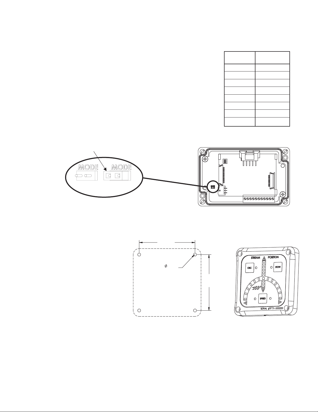
5.7 COMMUNICATION INTERFACE BOX
This Communication Interface Box converts discrete input signals into serial communications for controlling the monitor. The discrete
input signals can be from a joystick, toggle switches, relay contacts or Canbus output module. The interface box accepts +12/24 VDC
signals, but can be field changed to accept ground signals. The installer will need to mount the interface box and connect the cable to a
primary operator station or directly to themonitor.
5.7.1 ENCLOSURE MOUNTING
Select proper enclosure location. Enclosure is designed to be surface mounted and the size
is 5” x 3 1/8” (127 x 80mm). Height of enclosure is 2 3/8” (60mm). Refer to Figure 5.6.1 for
mounting hole dimensions.
5.7.2 ELECTRICAL WIRING
See section 5.1.2C for connecting power & communication cable. See section 5.10 if
connecting directly to the monitor.See section 5.7.2 for connecting inputs cable.
5.7.3 INPUTS SIGNAL CONFIGURATION
The Communication Interface Box is shipped from the factory configured to accept +12/24
VDC input signals, but can be field changed to accept ground input signals.
To changethe configuration:
1. Remove lid from enclosure.
2. Remove jumper to select GROUND inputs or install jumper to select VOLTAGEinputs.
3. Replace lid. Verify rubber seal is clean and undamaged. Verify that no wires are caught
between lid and box.
MODE JUMPER
GROUND
INPUTS
VOLTAGE
INPUTS
Figure 5.7.3
Communication Interface Box
Function
UP
DOWN
LEFT
RIGHT
FOG
STREAM
SPEED
STOW
Communication Interface
Wire Color/Function
Interface Box
Cable Color
WHITE
YELLOW
BROWN
GREEN
ORANGE
BLACK
Figure 5.7.2
BLUE
RED
5.8 MONITOR POSITION DISPLAY
The monitor positiondisplay is supplied with a 10' (3 m) long 4-conductor cable. The installer will needto surface mount the enclosure in
a dry area and connect the cable to power and the communication link of the monitor. Display is designed for use with 180° total
horizontal axis travel.
5.8.1 ENCLOSURE MOUNTING
Select proper location for display. The
display is not weatherproof and needs to be
inside a protected area such as in the cab.
MOUNT ENCLOSURE WITH
(2) #10 FASTENERS.
TIGHTEN SECURELY.
3-1/2”
(89 mm)
7/32”
(5.5 mm)
3-1/2”
(89 mm)
Fig 5.8.1 - Monitor Position Display Hole Dimensions
5.8.2 ELECTRICAL WIRING
The monitor position display needs to be connected to +12/24VDC (red) and ground (black). The blue & white wires from the position
display cable need to be connected to the blue & white wires from the monitor. A terminal box or a high quality, protected splice can be
used to make these connections. See section 5.10 for connecting power and communication cable.
5.9 CONNECTING MONITOR CABLE DIRECTLY TO PROTECTED POWER SUPPLY
The electric RC monitor has an operator station, which is fully functional, mounted on the monitor. If no other operator stations are
selected, the installer will only need toconnect power to complete the installation.
5.9.1 ELECTRICAL WIRING
Route cable from monitor and connect to a protected circuit from the truck’s power distribution center. Connect the red wire to positive
and the black wire to negative (ground). Cut anddiscard blue and white wires.
19
Page 20
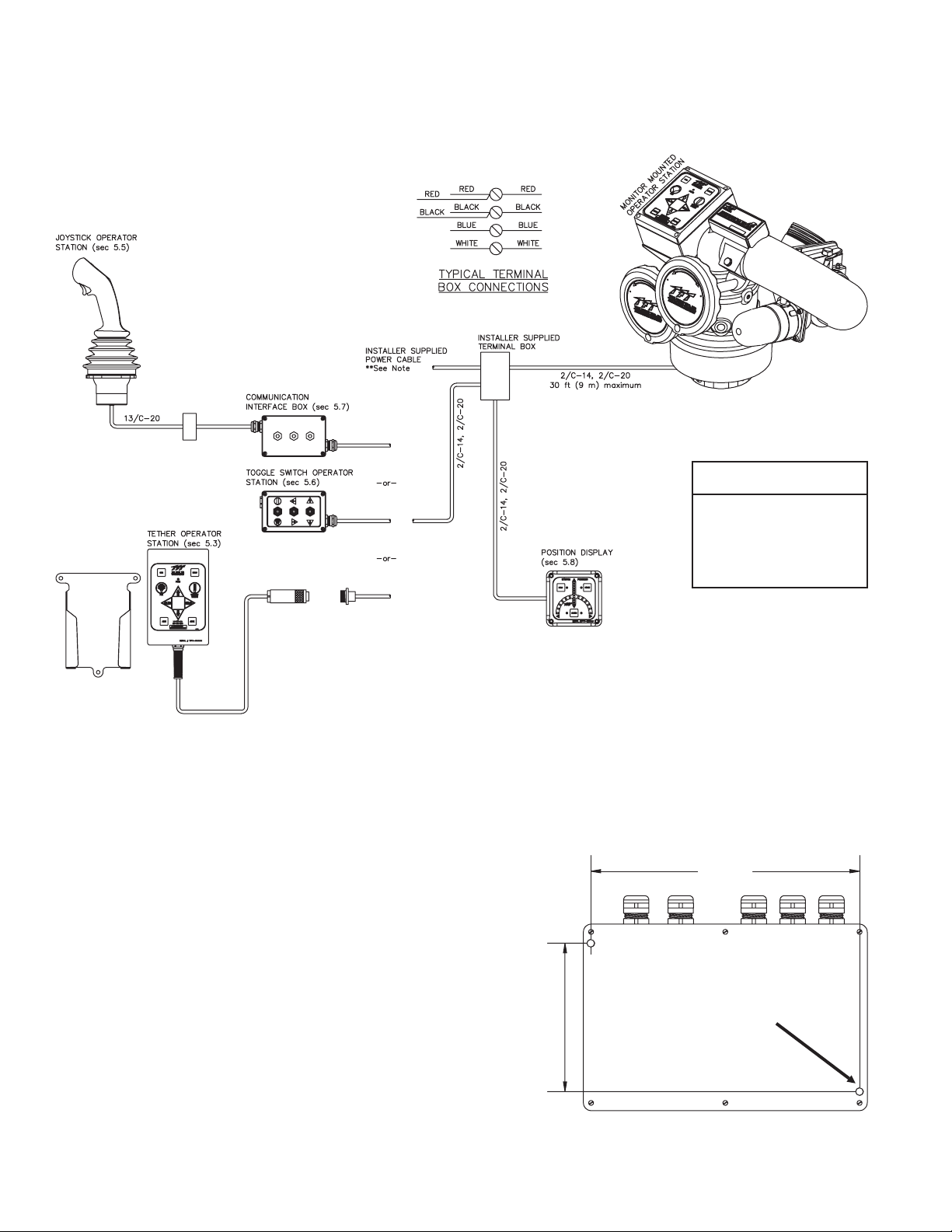
5.10 OPERATOR STATION INSTALLED DIRECTLY ON MONITOR
The electric RC monitor can be directly connected to a protected power supply, see section 5.9, and then be controlled by one of the
following without the use of a Y4E-RP,primary operating station.
• Tether Operator Station, seesection 5.3 for holster and receptacle mounting.
• Toggle Switch OperatorStation, see section5.6 for mounting.
• Communication Interface Box, see section 5.7 for mounting.
Recommended
Cable Gauge
Max Length Gauge
40ft.......14AWG
65ft.......12AWG
80ft......2-14AWG
105ft......10AWG
130ft .....2-12AWG
NOTE: To avoid excessive voltage drop at monitor operator station, do not
lengthen factory supplied power or monitor cable. Power cable selection is critical.
Voltage supplied to TERMINAL BOX should not fall below 13 volts when monitor is
in operation.
Figure 5.10
(operator station directly to monitor installations)
Electrical Components
5.11 ELECTRICAL RC MONITOR AERIAL TRUCK INSTALLATION
When installing the electric RC monitor on an aerial device truck, refer
to section 5.11.2.1 or 5.11.2.2.
5.11.1 ELECTRONICS ENCLOSURE MOUNTING
Select proper enclosure location. Enclosure is designed to be surface
mounted and the size is 5 3/4” x 8 3/4” (146 x 222mm). Height of
enclosure is 2 1/4” (57mm). Refer to Figure 5.11.1 for mounting hole
dimensions.
5.11.2 ELECTRICAL WIRING
On aerial devices, the installer will supply the required cables that run
up the ladder or boom. Be sure to perform voltage drop calculations to
verify that the supply voltage will remain at an acceptable level during
monitor operation.
4.56
(116 mm)
8.25
(210 mm)
MOUNT ENCLOSURE WITH
(2) 1/4-20 FASTENERS
TIGHTEN SECURELY
20
Fig 5.11.1
Electrical Enclosure
Mounting Hole Dimensions
Page 21
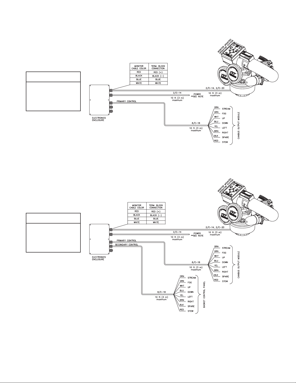
5.11.2.1 LADDER INSTALLATION ELECTRICAL WIRING (-L MODELS)
The electronics enclosure converts discrete input signals into serial communications for controlling
the monitor. The discrete input signals can be from a joystick, toggle switches, relay contacts or
Canbus output module. The electronic interface accepts +12/24 VDC signals, but can be field
changed to accept ground signals.
The electronics enclosure isconfigured sothat signalsconnected tothe PRIMARY CONTROL cable
will override any other operator stations (see section 6.2.1).
See Figure 5.11.2.1for wiring connections.
Recommended
Cable Gauge
Max Length Gauge
40ft.......14AWG
65ft.......12AWG
80ft......2-14AWG
105ft......10AWG
130ft .....2-12AWG
NOTE: To avoid excessive voltage drop at monitor
operator station, cable selection is critical.
Voltage supplied to ELECTRONICS ENCLOSURE should
not fall below 11 volts when monitor is in operation.
Figure 5.11.2.1
Electrical Components
(ladder installations)
5.11.2.2 PLATFORM INSTALLATION ELECTRICAL WIRING
The electronics enclosure converts discrete input signals into serial communications for controlling
the monitor. The discrete input signals can be from a joystick, toggle switches, relay contacts or
Canbus output module. The electronic interface accepts +12/24 VDC signals, but can be field
changed to accept ground signals.
The electronics enclosure isconfigured sothat signalsconnected tothe PRIMARY CONTROL cable
will override any other operator stations (see section 6.2.1).
See Figure 5.11.2.2for wiring connections.
Recommended
Cable Gauge
Max Length Gauge
40ft.......14AWG
65ft.......12AWG
80ft......2-14AWG
105ft......10AWG
130ft .....2-12AWG
NOTE: To avoid excessive voltage drop at monitor
operator station, cable selection is critical.
Voltage supplied to ELECTRONICS ENCLOSURE
should not fall below 11 volts when monitor is in
operation.
Figure 5.11.2.2
Electrical Components
(platform installations)
5.12 ELECTRIC NOZZLE ACTUATOR WIRING
The electric RC monitor is designed to control and is factory wired for a TFT electric actuated nozzle. Task Force Tips nozzles are
available with a male cord plug. After mounting the appropriate nozzle onto the monitor, plug the male cord from the nozzle into the
female cord located on the outlet of the monitor. Make sure the two coupling nuts are tightened securely to ensure a proper watertight
seal.
If retrofitting an existing TFT nozzle, a male cord plug (TFT #Y5285) can be purchased and installed in place of the existing actuator
cord. Please consult factory for installation.
21
Page 22

6.0 OPERATION
6.1 OVERRIDE HANDWHEELS
In the event of electrical system failure of the monitor or firetruck, Hurricane RC is factory supplied with handwheels so the monitor may
be manually operated. The factory-supplied handwheels are 6 inches in diameter. To make the Hurricane RC more compact, the
handwheels may be removed.
6.2.1 OPERATOR STATIONS
The electric Hurricane RC monitor has seven different styles of operator stations for use in various locations on the fire truck or fire
ground.
The design of the operator station communications allows users to override commands on other stations. The "last" button pressed has
control. The overridden user can regain control by releasing his/her button and pressing again. The wireless and joystick operator
stations cannot override commands fromthe primary operator station they are wired into, but can override other stations.
Platform and ladder electronics enclosures are pre-configured for one set of inputs to have a master override feature. The operator
station connected to these inputs, typically at the base of the ladder,will override any other operator station.
Any operator station with a communication board or connected to a communication board can be field configured with the master
override feature. This allows the user to setup an operator station on the fire truck or fire ground as the master override station. See
Section 6.2.2 for details.
6.2.1.1 MONITOR MOUNTED OPERATOR STATION
This operator station is factory installed on the monitor and is used by personnel right at the monitor.
6.2.1.2 PRIMARY OPERATOR STATION
This operator station is installed on the truck, for example the pump operator's panel. It is used to operate the monitor from a location on
the truck.
6.2.1.3 OPTIONAL OPERATOR STATION
This operator station allows the monitor tobe operated from an additional location on the truck.
6.2.1.4 TETHER OPERATOR STATION
This operator station is tethered to the truck with either a 30 foot (9 meter) cable or a 100 foot (30.5 meter) cable. It is used to move
slightly away from the truck to get a better view for redirecting the monitor.
6.2.1.5 WIRELESS OPERATOR STATION
This operator station uses RF signals to control the monitor. It is used to move far away from the truck to get a better view for redirecting
the monitor. Maximum range is 500 ft (152 meters). The wireless transmitter is coded to a particular monitor so several wireless
monitors may be in use at the same location without interference. It uses rechargeable batteries that will give 160 hours of continuous
operation when fully charged. When not in use the wireless transmitter should be kept in its charging base. The transmitter will turn on a
red LED to warn the operator when the battery charge is low.After thispoint there are less than 8 hours of continuous use available.
To activatethe transmitter, press the green buttonat the top. While the transmitter is active, the yellow LED will blink continuously.
Pressing the red button at the bottom will deactivate the transmitter. The transmitter will automatically deactivate after 10 minutes if no
buttons are pressed.
6.2.1.6 JOYSTICK OPERATOR STATION
This operator station is installedin a protected location and allows the monitor to be controlled bya joystick.
6.2.1.7 TOGGLE SWITCH OPERATOR STATION
This operator station allows the monitor tobe operated by three toggle switches.
22
Page 23
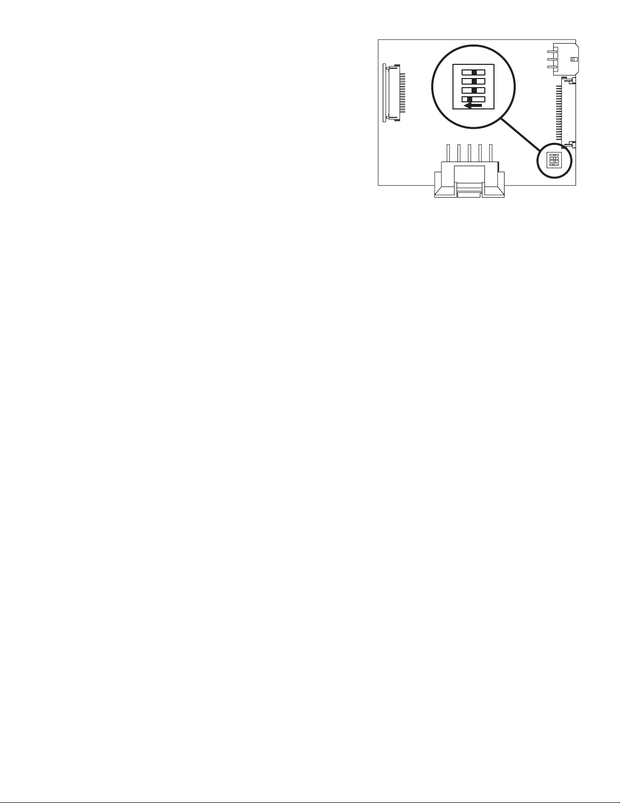
6.2.2 MASTER OVERRIDE FEATURE (DIP #1)
Any operator station with a communication board can be
reconfigured with the master override feature. These stations
include the Y4E-RP, Y4E-RO, Y4E-CT-30, Y4E-CT-100,
Y4E-TS, or any inputs connected to an Y4E-COMM. To
enable the master override feature on an operator station,
follow these steps:
ON CTS
4
3
12
1. Remove lid from enclosure.
2. Locate DIP switches on communication board.
3. Slide DIP switch #1 to theON position.
4. Replace lid. Verify rubber seal is clean and undamaged.
Verifythat no wires are caught between lid and box.
Figure 6.2.2
6.2.3 STOW FEATURE
Master Override Setup
The STOW position needs to be programmed during installation. The monitor needs to “find” two (2) hard stops, one for each axis,
before the monitor can move to the STOW position. When programming, the first two commands teach the monitor where to find the
hard stops. This guarantees that the position is accurate. From that point, the programmer can program the move to the final STOW
position.
During normal operation, each time the STOW button is pressed, the monitor moves the nozzle to the full straight stream position,
moves to each programmed hard stop, and then moves to the STOW position. While the monitor is performing the STOW feature,
pressing any button will stop the monitor.
6.2.3.1 PROGRAMMING
STOW programming must be initiated within 1 minute of applying power to monitor. After 1 minute, programming access is blocked.
Power must then be cycled to reset 1 minute timer.
Press and hold STOW button (~10 seconds) untilLED blinks. Release button. LED will continue to blinkwhile in program mode.
FIRST AXIS TO MOVE:
Press release LEFT/RIGHT or UP/DOWN button of axis that will move to first hard stop. LED will blink rapidly when hard stop is
and
reached.
SECOND AXIS TO MOVE:
Press release LEFT/RIGHT or UP/DOWN button of axisthat willmove tosecond hard stop. LED willblink rapidlywhen hardstop is
and
reached.
MOVE TO STOW POSITION:
Use LEFT/RIGHT or UP/DOWN buttons to move monitor to first point of stow routine, press release STOW button. LED will blink
rapidly to acknowledge position.
Repeat until pattern is complete (up to10 points).
Press hold STOWbutton until LED turns off. Release button.
and
and
6.2.3.2 STOW PROGRAMMING EXAMPLE
- Press hold STOWbutton until LED blinks.
and
- Press release UPbutton, monitor will move until hard stop reached. LED blinksrapidly.
and
- Press release RIGHTbutton, monitor will move until hard stop reached. LED blinks rapidly.
and
- Press LEFT button to move 45degrees, Press release STOWbutton. LED blinks rapidly.
- Press DOWN button to move 90 degrees, Press release STOW button. LED blinks rapidly.
- Press hold STOWbutton until LED turns off.
and
and
&
6.2.4 OSCILLATE FEATURE
The OSCILLATE feature allows the user to program a repeating pattern to control the horizontal and vertical axes of the monitor. While
in the OSCILLATE pattern, the monitor will pause while the user changes the stream pattern. Pressing any other button will stop the
OSCILLATEpattern.
A label is supplied with each operator station that can be mounted on or near the station as a reminder of how to program the
OSCILLATE pattern. The OSCILLATE pattern needs to be programmed before use. The pattern will be cleared each time power is
cycled to the monitor.For fixed monitors, the monitor may be configured to store the program permanently. See Section6.2.4.2.
23
Page 24
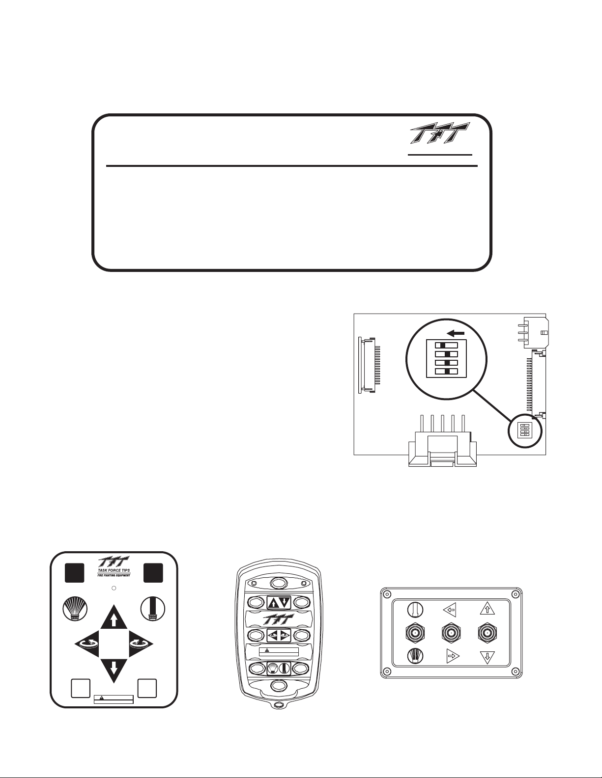
6.2.4.1 PROGRAMMING
- Move monitor to starting point of pattern.
- Press and hold OSC button (~5 seconds) until LED blinks. Release button. LED will continue toblink while in program mode.
- Move monitor to second point, press OSC button. LED willblink rapidly to acknowledge position.
- Repeat until pattern is complete (up to65 points).
- Press hold OSC button until LEDturns off. Release button.and
TO OSCILLATE:
Press & release OSC button.
Pattern must be programmed first.)
(
TO STOW:
Press & release STOW button.
(Programmable, refer to manual.)
OSCILLATE PATTERN PROGRAMMING:
1)
Move monitor to starting point of pattern.
2)
Press & hold OSC button until LED blinks. LED will continue to blink in program mode.
3)
Move monitor to 2nd point, press OSC button. LED will blink rapidly to acknowledge position.
4)
Repeat until pattern is complete.
5)
Press & hold OSC button until LED turns off.
NOTE: PATTERN WILL BE CLEARED UPON POWER LOSS.
Figure 6.2.4.1
Operator Station Label
6.2.4.2 OSCILLATE PATTERN RETAIN FEATURE (DIP #4)
The monitor can be configured so that upon power up, the OSCILLATE
pattern is retained. The OSCILLATE pattern will need be programmed at
least one time(see section 6.2.4.1). To enable the OSCILLATE pattern retain
feature on a monitor follow these steps:
1. Remove lidfrom monitor operator station.
2. Locate DIPswitches on communication board.
3. Slide DIPswitch #4 to the ON position.
4. Replace lid. Verify rubber seal is clean and undamaged. Verify that
no wires are caught between lid and box.
5. Program OSCILLATE pattern.
®
TASK FORCE TIPS
FIRE FIGHTING EQUIPMENT
800-348-2686
www.tft.com/tornado
Y5705
4
3
ON CTS
12
Figure 6.2.4.2
Oscillate Pattern Retain Setup
6.2.5 OPERATOR STATION PANELS
The operator stations are all equipped with the same monitor movement functions. From the operator stations, the operator can
command the monitor up, down, left, right and command the nozzle pattern shaper from fog to straight stream. Operator stations
supplied with the membrane switch, shown on the left below,allow the operator to program and perform the oscillate and stow features.
®
OSC
HOLD TO
PROGRAM
FOG STRAIGHT
AUX 1
POWER
800-348-2686
www.tft.com
WARNING
Read manual before use.
AUX 2
STOW
HOLD TO
PROGRAM
STREAM
AUX 2
Y5700
®
WARNING
Read manual before use.
Fig 6.2.5
Operator Station Button Layouts
24
Page 25
6.3 RECOMMENDED MONITOR STOWING POSITION
For truck mounted applications, it is recommended that the monitor be stowedin a position such that the monitor'snozzle rests against a
bracket or support surface. This will minimize bouncing of the nozzle when the apparatus is traveling.
properly stowed before moving the truck and know the overall height to avoid damage from overhead obstructions such as
doors or bridges.
On many vehicle installations, the monitor is the highest point on the apparatus. Often it is critical that the monitor be properly stowed
before driving to avoid damage to overhead obstructions, such as door openings. In these cases, the use of a switch wired into the
apparatus's "door open" circuit is highly recommended.The switch would be wired to give a "door open" signal if the monitor is not in the
stowed position. Due to the variety of possible mountings and nozzles, it is the installer’s responsibility to supply the appropriate switch
with mounting and wire it into their system.Always check stowed position of monitor before moving apparatus.
Always be sure the monitor is
6.4 AUTOMATIC DRAIN
Doing the following may disable the automatic drain:
Refer to the exploded view in Section 9.0.
1) Unscrewthe drain assembly from the monitor and remove the screw (#33) and washer (#28).
2) Turn over the rubber drain valve (#32) so that the raised edge is facing down, against the face of the housing (#31).
3) Reinstallthe washer and screw. Reinstall the drain assembly.
6.5 FLOWS AND PRESSURES
The Hurricane RC is designed for a maximum pressure of 200 psi (14 bar). Do not exceed these limits.
The stream exiting a monitor is very powerful and capable of causing injury and property damage.
CAUTION
Because the stream trajectory can obscure the view of the operator, it is recommended that a spotter be used to accurately direct the
stream.
Make sure the monitor is securely attached to the base and pointing in a safe direction beforewater
to the monitor is turned on. Use care in directing the stream.
25
Page 26
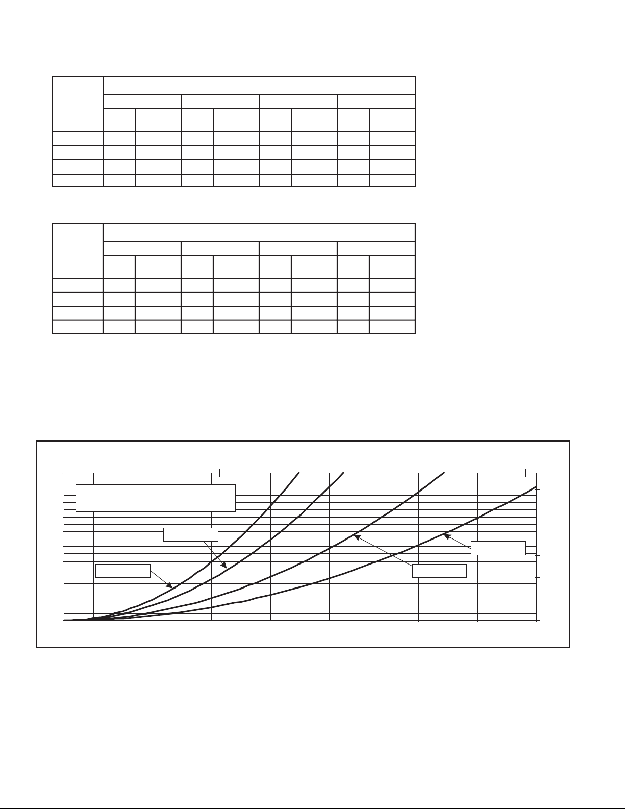
6.5.1 STACKED TIPS FLOW AND REACH
English Units
Nozzle Pressure (PSI)
Nozzle 40 60 80 100
Diameter Flow Reaction Flow Reaction Flow Reaction Flow Reaction
(inches) GPM lbf GPM lbf GPM lbf GPM lbf
1.375 360 120 440 180 500 240 560 300
1.50 420 140 520 210 600 280 670 350
1.75 580 190 700 290 810 380 910 480
2.00 750 250 920 380 1060 500 1190 630
Metric Units
Nozzle Pressure (BAR)
Nozzle 2.8 4.1 5.5 7
Diameter Flow Reaction Flow Reaction Flow Reaction Flow Reaction
(MM) l/min kg l/min kg l/min kg l/min kg
35 1360 50 1670 80 1890 110 2120 140
38 1590 60 1970 100 2270 130 2540 160
45 2200 90 2650 130 3070 170 3440 220
50 2840 110 3480 170 4010 230 4500 290
1 bar = 14.5 psi
1 gal = 3.785 l/min
1 bar = 14.5 psi
1 gal = 3.785 l/min
FIG 6.5.1A
Stacked Tip Flow Table
0 1000 2000 3000 4000 5000 6000
200
180
160
140
120
100
80
PRESSURE (PSI)
60
40
20
0
0 200 400 600 800 1000 1200 1400 1600
STACK TIP PERFORMANCE
(PRESSURE IS NOZZLE EXIT PITOT PRESSURE)
1 1/2" TIP
1 3/8" TIP
(LPM)
2" TIP
1 3/4" TIP
FLOW (GPM)
1.2
1.0
0.8
0.6
0.4
PRESSURE (BAR)
0.2
0.0
FIG 6.5.1B
Stacked Tip Flow Graph
26
Page 27
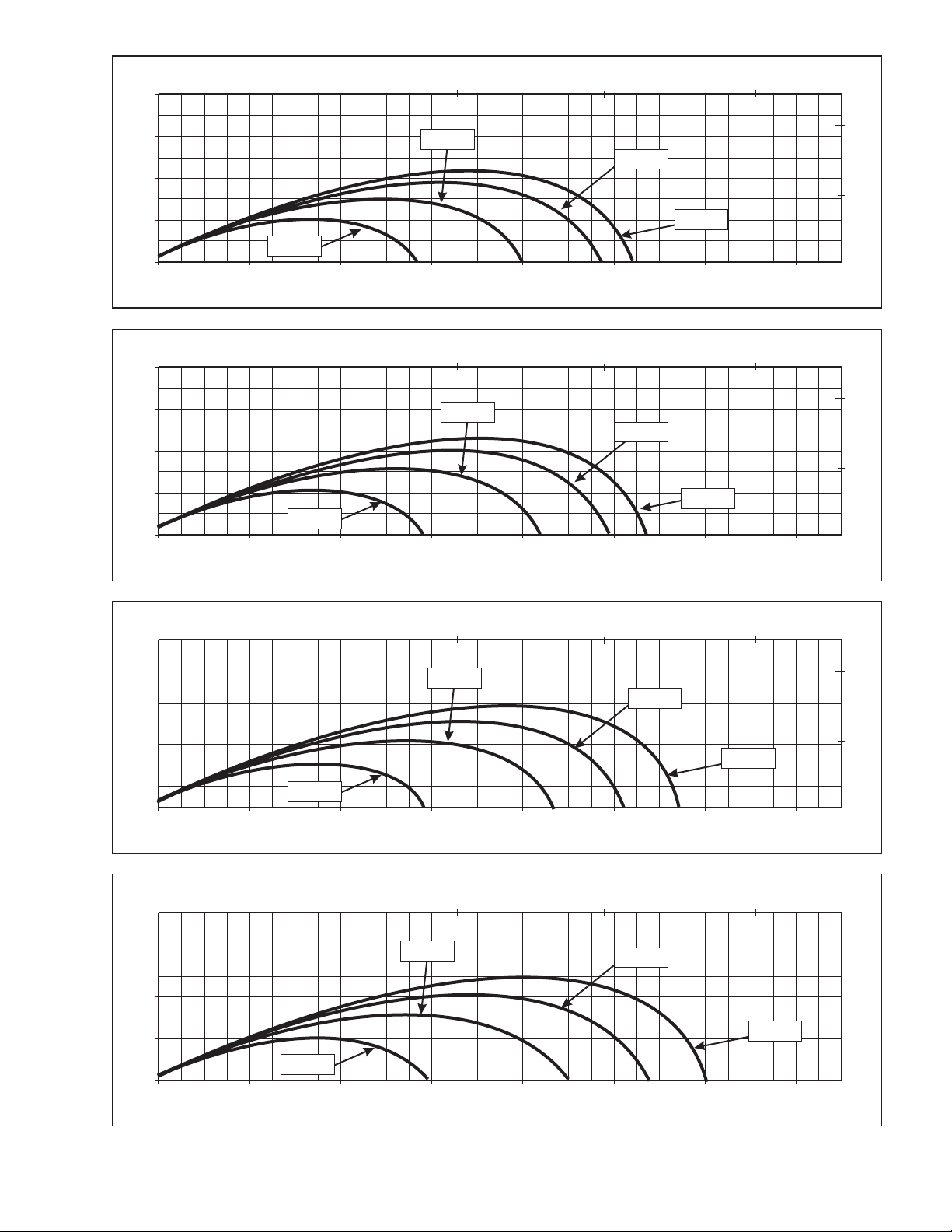
1.375 INCH TIP
0.0 40.0
80
20.0 60.0
HORIZONTAL DISTANCE (M)
80.0
60
60 PSI
80 PSI
40
20
100 PSI
40 PSI
0
VERTICAL DISTANCE (FEET)
0.0 40.0 80.0 120.0 160.0 200.0 240.0 280.0
HORIZONTAL DISTANCE (FEET)
1.50 INCH TIP
0.0 40.0
80
60
20.0 60.0
HORIZONTAL DISTANCE (M)
80.0
60 PSI
80 PSI
40
20
100 PSI
40 PSI
0
VERTICAL DISTANCE (FEET)
0.0 40.0 80.0 120.0 160.0 200.0 240.0 280.0
HORIZONTAL DISTANCE (FEET)
20
10
20
10
VERTICAL DISTANCE (M)
0
VERTICAL DISTANCE (M)
0
1.75 INCH TIP
0.0 40.0
80
60
20.0 60.0
HORIZONTAL DISTANCE (M)
80.0
60 PSI
80 PSI
40
20
100 PSI
40 PSI
0
VERTICAL DISTANCE (FEET)
0.0 40.0 80.0 120.0 160.0 200.0 240.0 280.0
HORIZONTAL DISTANCE (FEET)
2 INCH TIP
0.0 40.0
80
60
40
20
20.0 60.0
HORIZONTAL DISTANCE (M)
60 PSI
80.0
80 PSI
100 PSI
40 PSI
0
VERTICAL DISTANCE (FEET)
0.0 40.0 80.0 120.0 160.0 200.0 240.0 280.0
HORIZONTAL DISTANCE (FEET)
20
10
20
10
VERTICAL DISTANCE (M)
0
VERTICAL DISTANCE (M)
0
FIG 6.5.1C
Stacked Tips Stream Trajectory Graphs
27
Page 28
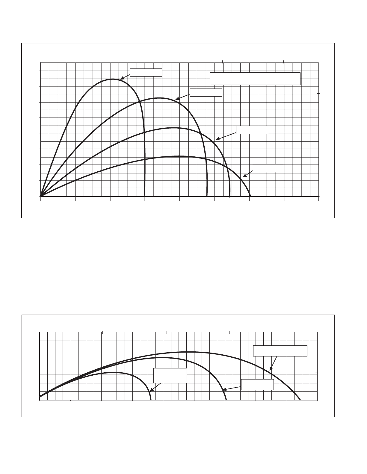
HORIZONTAL DISTANCE (METERS)
8020 40 600
160
75 DEGREES
2.0 INCH TIP, 100 PSI, 1190 GPM
140
60 DEGREES
120
100
80
60
VERTICAL DISTANCE (FEET)
40
20
0
0 40 80 120 160 200 240 280 320
HORIZONTAL DISTANCE (FEET)
This graph is approximate only.
Critical applications should be tested in actual conditions to verify adequate reach.
45 DEGREES
30 DEGREES
40
20
VERTICAL DISTANCE (METERS)
0
FIG 6.5.1D
Effects Of Elevation Of Trajectory
2.00 INCH TIP, 100 PSI, 1190 GPM
0 25 50 75 100
80
HORIZONTAL DISTANCE (M)
20 MPH TAILWIND
40
20 MPH
HEADWIND
NO WIND
0
VERTICAL DISTANCE (FEET)
0
40
80 120 160 200 240 280 320 360
HORIZONTAL DISTANCE (FEET)
20
10
VERTICAL DISTANCE (M)
FIG 6.5.1E
Effects of wind on reach
This graph shows approximately how a moderate wind can affect stream reach. 1 ft = 0.3048 m
28
Page 29
6.5.2 AUTOMATIC NOZZLES
Automatic nozzles maintain a constant pressure by adjusting their orifice to match the available flow. Consult the nozzle’s
manufacturer for maximum flow and pressure ratings. In all cases, do not exceed 1250 gpm (4500 l/min). TFT's Masterstream 1250
Nozzle has a 150-1250 gpm (600 - 4500 l/min) flow range. Masterstream 1250 Nozzle operating instructions (Item Number LIM-030)
are available on TFT's website: www.tft.com
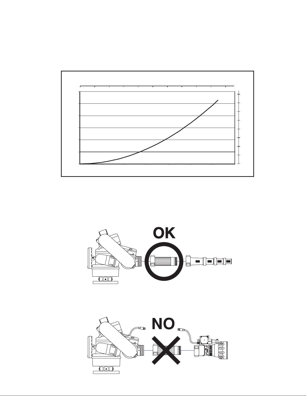
6.5.3 HURRICANE RC MONITOR FRICTION LOSS
The friction loss of the Hurricane RC Monitor isshown below in Fig.6.5.3.
FLOW (L/min)
0
30.0
25.0
20.0
1000 2000 3000
4000 5000
2.0
1.5
15.0
10.0
PRESSURE LOSS (PSI)
5.0
0.0
0
200
400
600 800 1000 1200 1400
FLOW (GPM)
1.0
0.5
0
PRESSURE LOSS (BAR)
FIG 6.5.3
Hurricane Monitor Friction Loss
6.6 STREAM STRAIGHTENERS
6.6.1 STREAM STRAIGHTENERS WITH STACKED TIP NOZZLES
Stream quality and reach, especiallywith stacked tip(smooth bore)nozzles, isgenerally improved witha streamstraightener because
the water must make many bends before it reachesthe nozzle.
6.6.2 STREAM STRAIGHTENERS WITH FOG NOZZLES
When using a fog nozzle, it is recommended that no stream straightener be used sincethe fog nozzle's flow path generally serves as a
stream straightener. Use of a stream straightener with a fog nozzle will increase the stress on the monitor's gear train and may lead to
premature wear.
29
Page 30
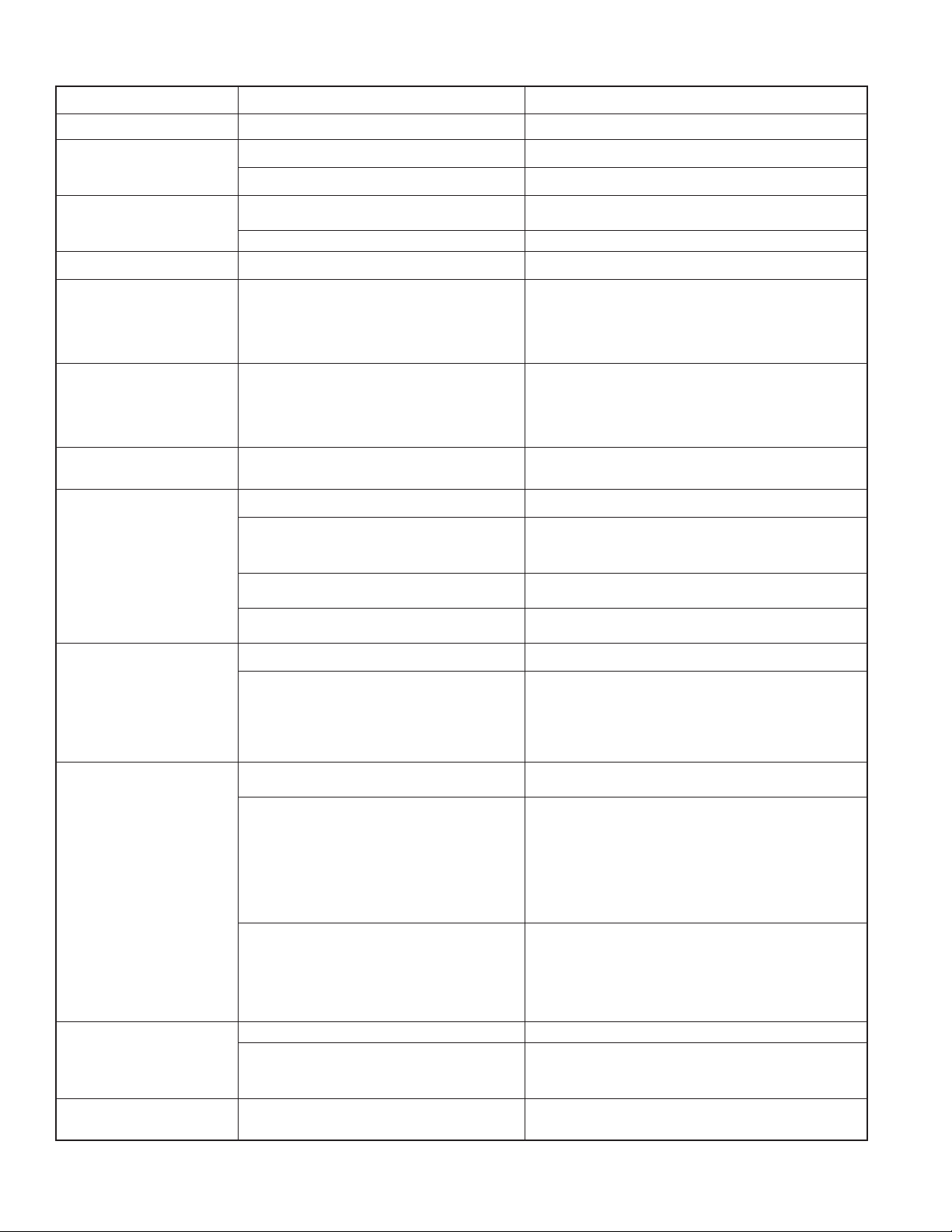
7.0 TROUBLE SHOOTING
SYMPTOM
Leaks
Elevation Binding
Horizontal Rotation Binding
No Power LED
Power LED On But No
Operation
Operation only from monitor
operator station. STOW, &
OSC LED’s on remote station
blink slowly when button
pressed.
Operation only from monitor
control station
One Axis Fails To Operate
From Any Control Station
POSSIBLE CAUSE
Debris or damage in seal area
Debris or damage to elevation drive parts
Lack of lubricant
Debris or damage to horizontal drive parts
Lack of lubricant
Polarity reversed
Low voltage due to:
- wire gauge too small
- wire length too long
- poor connection
- inadequate apparatus electrical system
Incorrect communication wiring
Communication board code version incompatible
Loose motor wiring connection
motor
Bad control board
REMEDY
Clean out debris or replace damaged parts
Clean out debris or replace damaged parts
Grease, see section 8.1
Clean out debris or replace damaged parts
Grease, see section 8.1
Check wiring and reverse polarity
Check connections and wiring per section 5.1.2
Check blue/white communication wiring
Verify code versions on monitor and all operator stations
Check axis motor connection
Interchange motor control boards and check if problem
persists with same axis, If not, replace motor control
board.
Vertical/Horizontial axis will
not speed up
Vertical/Horizontial axis runs
only in fast speed
Vertical/Horizontial axis only
runs ~5 seconds and then
stops.
STOW & OSC LED’s on
mnitor control station blink
rapidly when pressing
UP/DOWN or RIGHT/LEFT
button.
Bad motor
Bad membrane switch
Loose encoder wiring connection
Bad motor encoder
Loose encoder wiring connection
Bad motor encoder
Loose encoder wiring connection
Bad motor encoder
Loosen encoder wiring connection.
Bad motor encoder.
Interchange motor control boards. Check if problem
persists with same axis, If yes, replace motor.
Replace membrane switch / operator station
Check axis encoder connection
Interchange motor control boards. Check if problem
persists with same axis. If yes, replace motor.
Remove encoder cover and check for RED light just below
disk. If no light, encoder is bad. Replace motor.
Check axis encoder connection
Interchange motor control boards. Check if problem
persists with same axis. If yes, replace motor.
Remove encoder cover and check for RED light just below
disk. If no light, encoder is bad. Replace motor.
Check axis encoder connection.
Interchange motor control boards. Check if problem
persists with same axis. If yes, replace motor.
Remove encoder cover and check for RED light just below
disk. If no light, encoder is bad. Replace motor.
Check axis encoder connection.
Replace motor.
Cycle power to clear encoder fault.
Unable to program STOW
patte.
Program enable timer expired.
Cycle power and enter STOW programming mode within
1 minute
30
Page 31

8.0 MAINTENANCE AND INSPECTION
The Hurricane RC monitor requires little maintenance. The monitor should be kept clean and free of dirt. All controls should be
checked for freedom of movement and proper operation before each use. Any
inoperable or damaged parts should be repaired or replacedimmediately.
• Make sure that the monitor's handwheels rotate freelyand without binding throughout its range of travel.
• Make sure that there are no leaks whenthe monitor is flowing water.
• Make sure the nozzle is free of debris.
Consult factory for recommended service procedure.
8.1 LUBRICATION
8.1.1 ELEVATION CONTROL WORM GEAR
Turn the hand wheel to raise the nozzle to its highest position and pump medium viscosity automotive chassis grease into the grease
fitting on the Elevation worm gear housing until excessappears at the joint. See Fig. 3.2 for grease zerk location.
8.1.2 HORIZONTAL ROTATION WORM GEAR
The Hurricane RC monitor generally should not require greasing in the Horizontal (left-right) worm gear.In the event that the operation
becomes stiff, grease may be applied to the horizontal worm gear grease port shown in Fig. 3.2. Use medium viscosity automotive
chassis grease. Apply only enough grease to restore normal operation. If greasing does not restore normal operation, inspect for other
causes of stiff operation.
Note: Do not over pump grease to Horizontal worm gear. The monitor's Horizontal worm gear greased areas lead to the wire
skirt/cable guide that would trap several pounds of grease before becoming visible.
8.2 PERFORMANCE TESTING
Performance tests should be conductedon theHurricane RC monitor after repairs aremade, or any time a problem isreported to verify
operation in accordance with Task Force Tips test procedures. Consult the factory for the test procedure that corresponds to the
model and serial number of your monitor. Any equipment that fails the test criteria should be removed from service immediately.
Equipment can be returned to the factory for serviceand testing.
31
Page 32
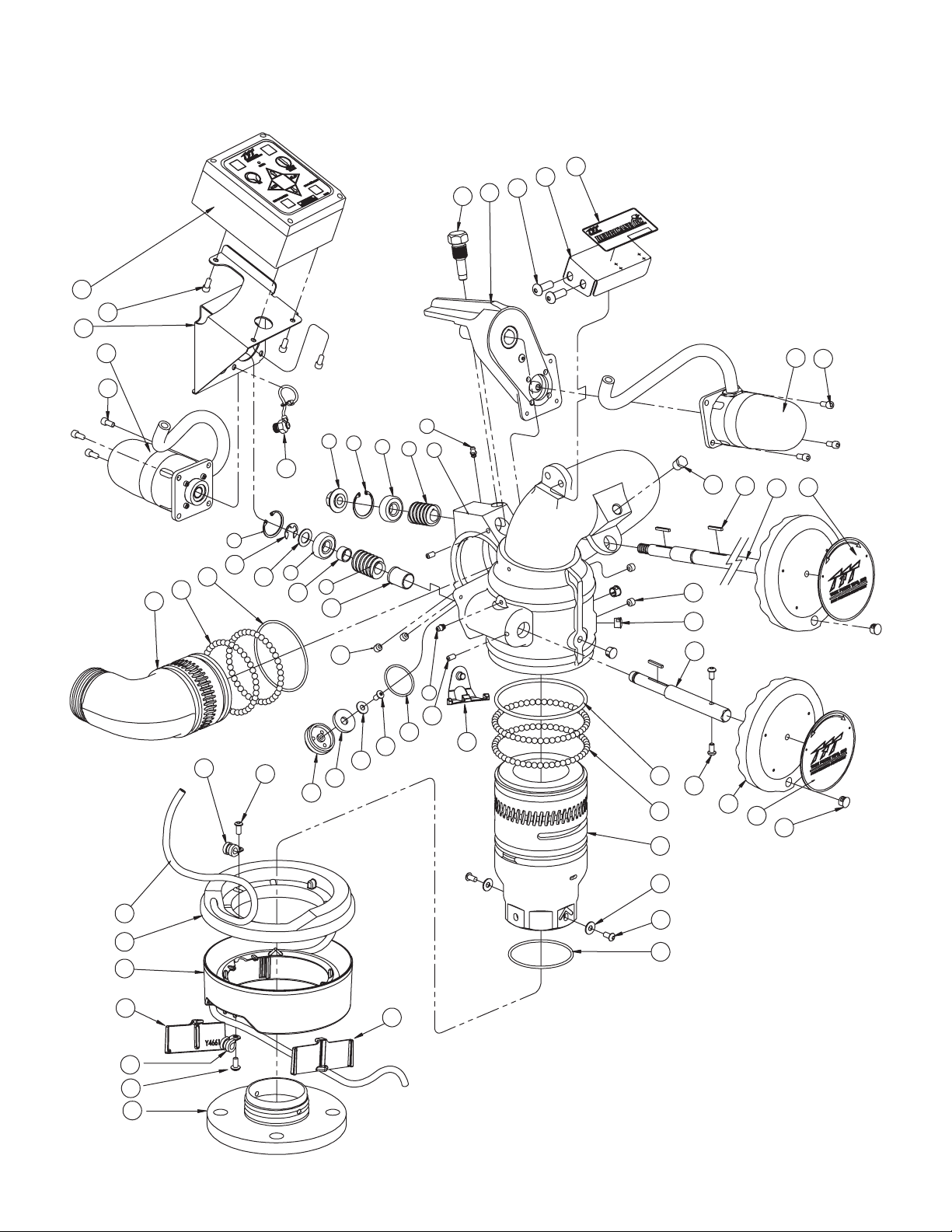
9.0 EXPLODED VIEW DRAWINGS AND PARTS LIST
9.1 HURRICANE RC MONITOR ASSEMBLY
8
7
43
13
44
12
13
11
10
9
12
13
42
41
48
40
39
1
2
50
2
3
38
24
37
4
36
18
28
32
31
3
33
34
6
4
5
14
35
15
18
19
20
6
52
25
24
26
27
23
22
16
17
21
45
46
47
51
28
29
30
51
48
24
49
32
Page 33

HURRICANE RC MONITOR PARTS LIST
# DESCRIPTION QTY PART #
1 SHAFT NUT 1 X210
2 SNAP RING 2 VR4220
3 BEARING 2 VM4250
4 WORM W/ KEYWAY 2 X220
5 BELL / BIG BEND ASSEMBLY 1 X806
6 GREASE FITTING 1/4-28 2 VT25-28ZERK
7 HEX MOUNTING SCREW 1 X258
8 CHAIN DRIVE ASSEMBLY 1 X888
9 3/8-16 x 1 BHCS 2 VT37-16BH1.0
10 LABEL BRACKET 1 X395
11 LABEL: HURRICANE RC 1 XL300
12 GEAR MOTOR ASSEMBLY 2 Y4950
13 1/4-28 x 1/2 SHCS 9 VT25-28SH500
14 1/4"NPT HEX HEAD PLUG 1 VFHP2M
15 KEY 1/8 x 1.00 3 X225
16 ELEV. SHAFT ASSEMBLY 1 X270
17 LABEL; DOWN <-> UP 1 Y4175
18 3/8-24 x 5/16 SHCS CUP PT. 4 VT37-24SS312
19 DOME PLUG 5 VM4124
20 DRIVE SHAFT 1 Y4160
21 DOME PLUG 2 VM4124
22 LABEL; LEFT <-> RIGHT 1 XL108
23 HANDWHEEL 1 X281
24 1/4-20 x 1/2 BHCS 4 VT25-20BH500
25 O-RING-350 1 VO-350
26 BALL 5/16 TORLON (49) 98 VB.312TO
27 BASE CODE-RLF 3" ALUM 1 Y4405A
28 FLAT WASHER 1/4" 3 VW687X281-50
29 1/4-28 x 1/2 BHCS 2 VT25Y28BH504
30 O-RING-236 1 VO-236
31 DRAIN HOUSING 1 X375
32 DRAIN VALVE 1 X382
33 1/4-20 x 1/2 BHCS 1 VT25-20BH500
34 O-RING-130 1 VO-130
35 1/4-28 x 3/8 SHCS CUP PT. 2 VT25-28SS375
36 HEADED BUSHING 1 Y4141
37 SPACER 1 Y4150
38 SPACER WASHER 1 VW97X595-048
39 E-CLIP 5/8" EXT. 1 VR4295
40 O-RING-241 1 VO-241
41 BALL 5/16" TORLON (38) 76 VB.312TO
42 ELBOW 2.5"NH ALUM SILVER 1 X820NJ-SIL
43 CONTROL BOX - ASMBLY 1 Y5800
44 BOX BRACKET 1 X390
45 CABLE - POWER & COMM. 34 FEET Y5200
46 UPPER WIRE SKIRT 1 Y4650
47 LOWER WIRE SKIRT 1 Y4660
48 LOOP CLAMP 3/8" 2 Y4655
49 FLANGE 3"ANSI 150 ALUM 1 Y4410A
50 PLUG CAP W/ CHAIN ASMBLY. 1 Y5340
51 WIRE SKIRT RETAINER 2 Y4661
52 STOP BALL RETAINER 1 Y4651
33
Page 34
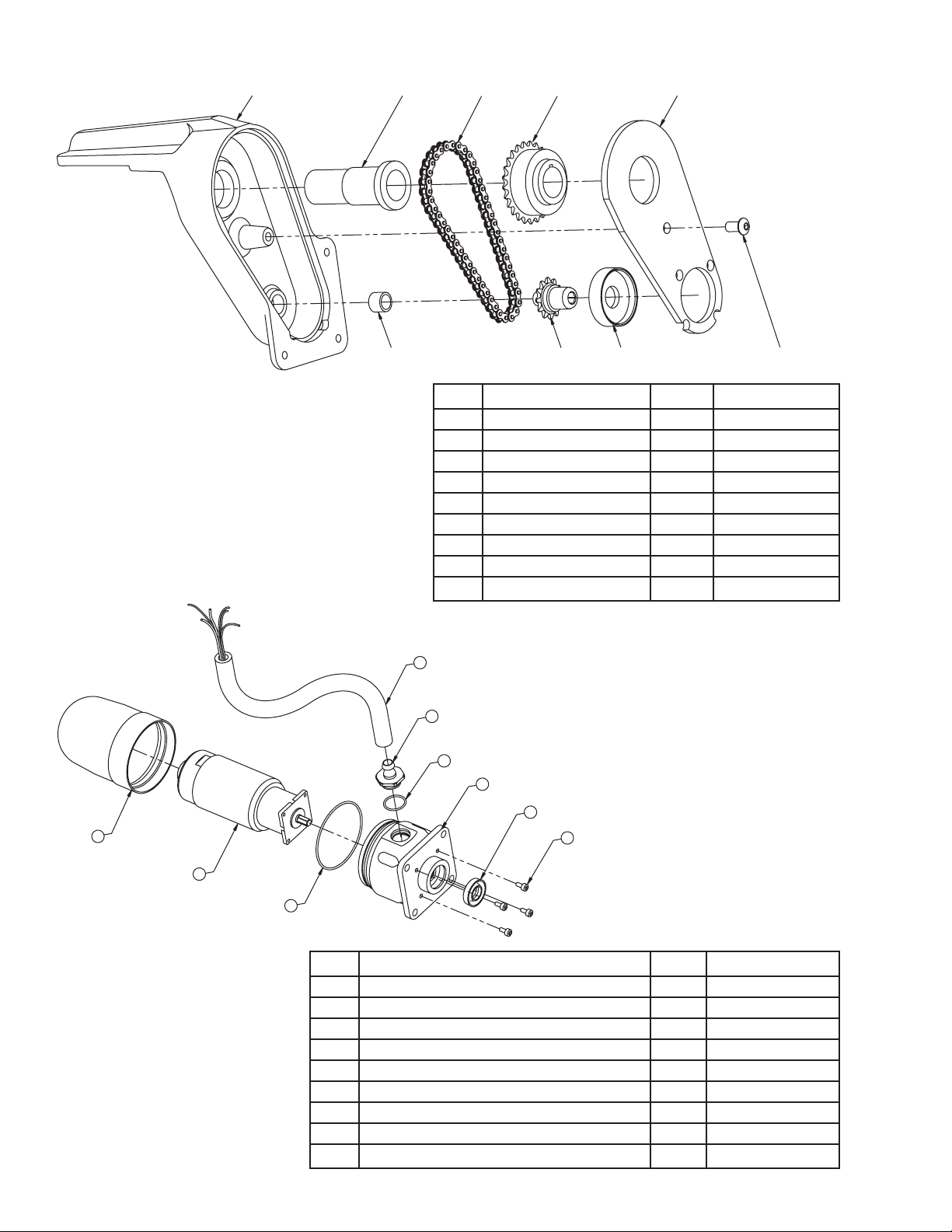
9.2 ELEVATION CHAIN DRIVE ASSEMBLY
1
2
4
5
8
9.3 GEAR MOTOR ASSEMBLY
3
6
7
9
# DESCRIPTION QTY PART #
1 HOUSING 1 X250
2 BUSHING - SHAFT 1 X251
3 BUSHING - DRIVE 1 X252
4 1 X255
ROLLER CHAIN RING
5 1 X254
SPROCKET - SLAVE
6 1 X253
SPROCKET - DRIVE
7 1 X256
BUSHING - MOTOR
8 1 X257
COVER
9 1 VT25-28BH500
1/4-28 x 1/2 BHCS
6
5
4
3
2
9
8
7
1
# DESCRIPTION QTY PART #
1 6-32 x 5/16 LONG SHCS WITH HEAD SEAL 4 VT06S32SH312
2 CUP SEAL 1.0625 x .5625 x 1/4 1 Y4620
3 MOTOR SOCKET 1 Y4615
41
O-RING-018 VO-018
51
CONDUIT FITTING Y5213
61
HOSE - 3/8" ID PUSH-LOK Y5250
71
O-RING-038 VO-038
81
GEAR MOTOR WITH ENCODER Y4610
91
ENCLOSURE Y4616
34
Page 35
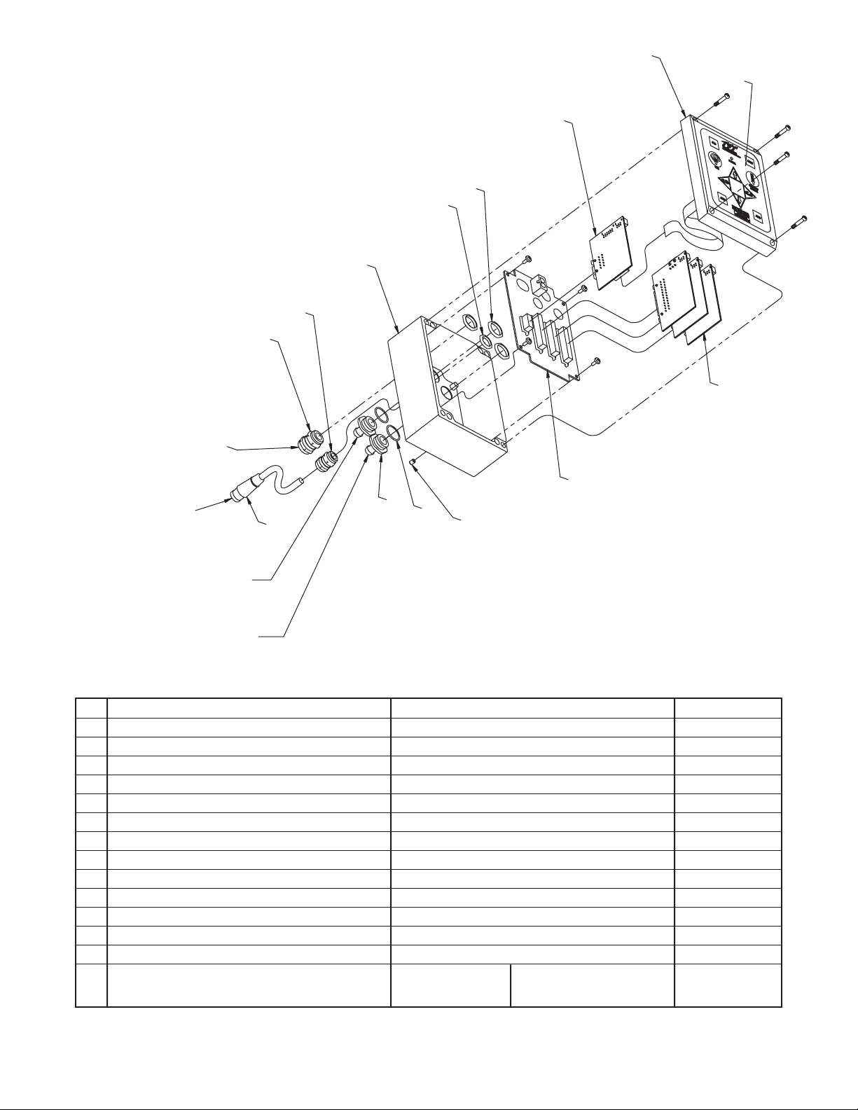
9.4 MONITOR CONTROL BOX ASSEMBLY
3
2
1
TO
POWER
CABLE
7
8
6
5
4
9
10
TO TFT
ER NOZZLE
MALE PLUG
14
13
12
11
TO HORIZONTAL
GEAR MOTOR
TO VERTICAL
GEAR MOTOR
# DESCRIPTION QTY. PART NO.
1 CABLE FITTING PG11 1 Y5205
2 CABLE FITTING PG9 1 Y5245
3 ENCLOSURE - BOX 1 Y5115
4 LOCKNUT - PG9 1 Y5246
5 LOCKNUT - PG11 3 Y5206
6 BOARD - COMMUNICATION 1 Y5110
7 ENCLOSURE - LID 1 Y5115
8 CONTROL SWITCH PAD 1 Y5700
9 BOARD - MOTOR CONTROL 3 Y5100
10 BOARD - MAIN 1 Y5105
11 V10-32 x 1/4 SET SCREW 1 VT10Y32SS250
12 O-RING-018 2 VO-018
13 CONDUIT HOSE FITTING 2 Y5213
14 FEMALE PLUG - 2 POLE
FOR HURRICANE RC NOZZLE CONNECTION
10.0" TOTAL 5.0" EXPOSED CABLE Y5280
LENGTH USED (NOT INCLUDING PLUG)
35
Page 36

10.0 WARRANTY
Task Force Tips, Inc., Valparaiso, Indiana 46383-6940 (“TFT”) warrants to the original purchaser of its Hurricane RC
Monitor(“equipment”), and to anyone to whom it is transferred, that the equipment shall be free from defects in material and
workmanship during the five (5) year period from thedate of purchase.
TFT’s obligation under this warranty is specifically limited to replacing or repairing the equipment (or its parts) which are shown by
TFT’s examination to be in a defective condition attributable to TFT. To qualify for this limited warranty, the claimant must return the
equipment to TFT, at 2800 East Evans Avenue, Valparaiso, Indiana 46383-6940, within a reasonable time after discovery of the defect.
TFT will examine the equipment. If TFT determines that there is a defect attributable to it, it will correct the problem within a reasonable
time. If the equipment is covered by this limitedwarranty,TFT willassume the expenses of repair.
If any defect attributable to TFT under this limited warranty cannot be reasonably cured by repair or replacement, TFT may elect to
refund the purchase price of the equipment, less reasonable depreciation, in complete discharge of its obligations under this limited
warranty.If TFT makes this election, claimant shall return the equipment to TFT free and clear of any liens and encumbrances.
This is a limited warranty. The original purchaser of the equipment, any person to whom it is transferred, and any person who is an
intended or unintended beneficiary of the equipment, shall not be entitled to recover from TFT any consequential or incidental
damages for injury to person and/or property resulting from any defective equipment manufactured or assembled by TFT. It is agreed
and understood that the price stated for the equipment is in part consideration for limiting TFT’s liability. Some states do not allow the
exclusion or limitation of incidental or consequential damages, sothe above may not apply to you.
TFT shall have no obligation under this limited warranty if the equipment is, or has been, misused or neglected (including failure to
provide reasonable maintenance) or if there have been accidents to the equipment or if it has been repaired or altered by someone
else.
THIS IS A LIMITED EXPRESS WARRANTY ONLY. TFT EXPRESSLY DISCLAIMS WITH RESPECT TO THE EQUIPMENT ALL IMPLIED
WARRANTIES OF MERCHANTABILITY AND ALL IMPLIED WARRANTIES OF FITNESS FOR A PARTICULAR PURPOSE. THERE IS NO
WARRANTY OF ANY NATURE MADE BY TFT BEYONDTHAT STATED IN THE DOCUMENT.
This limited warranty gives you specific legal rights, andyou may also have other rights which vary from state to state.
TASK FORCE TIPS, Inc.
MADE IN USA • www.tft.com
©Copyright Task Force Tips, Inc. 2004-2006
2800 E. Evans Ave., Valparaiso, IN 46383-6940 USA
800-348-2686 • 219-462-6161 • Fax 219-464-7155
LIX-300 January 24, 2006 Rev05
 Loading...