

INSTRUCTIONS FOR SAFE OPERATION AND MAINTENANCE
Read Instruction Manual before use. Operation of this device without understanding the manual
WARNING
WARNING
and receiving proper training can be dangerous and is a misuse of this equipment. Download
this manual from http://tft.com/. Call 800-348-2686 with any questions.
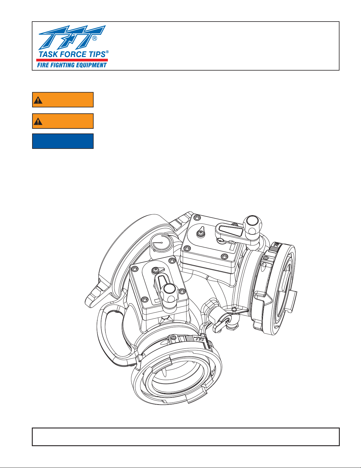
This instruction manual is intended to familiarize fi refi ghters and maintenance personnel with
the operation, servicing, and safety procedures associated with the LDH Gated Wye.
This manual should be kept available to all operating and maintenance personnel.
NOTICE
OPERATING RANGE
Pressure Max 300 PSI
Pressure Min Full Vac
Hydrostatic Proof Test: 900 PSI
MANUAL: LDH GATED WYE
TASK FORCE TIPS, INC.
MADE IN USA • www.tft.com
©Copyright Task Force Tips, Inc. 2012 LIA-540 April 16, 2012 Rev00
3701 Innovation Way, Valparaiso, IN 46383-9327 USA
800-348-2686 • 219- 462-6161 • Fax 219-464-7155
Table Of Contents
1.0 MEANING OF SAFETY SIGNAL WORDS
2.0 SAFETY
3.0 GENERAL INFORMATION
3.1 PARTS IDENTIFICATION AND MODELS
3.2 SPECIFICATIONS
3.3 CORROSION
3.4 USE WITH SALT WATER
4.0 INSTALLATION
4.1 CHANGING OFFSET OF CRANK HANDLE
4.2 STORZ SUCTION GASKET REQUEST
5.0 USE
5.1 VALVE POSITION INDICATOR
5.2 AIR VENT AND WATER DRAIN
5.3 PRESSURE RELIEF VALVE
5.4 SUCTION SCREEN
5.5 VALVE PRESSURE LOSS
6.0 MAINTENANCE
7.0 EXPLODED VIEWS & PARTS LISTS
7.1 LDH GATED WYE
7.2 PARALLEL SHAFT GEARBOX
7.3 PRESSURE RELIEF VALVE
7.4 BLEEDER
7.5 SIDE A (SINGLE SIDE) COUPLING COMPONENTS
7.6 SIDE B (DUAL SIDE) COMPONENTS
8.0 ANSWERS TO YOUR QUESTIONS
9.0 WARRANTY
DANGER
The member companies of FEMSA that provide emergency response
equipment and services want responders to know and understand the
following:
1. Firefi ghting and Emergency Response are inherently dangerous activities
requiring proper training in their hazards and the use of extreme caution
at all times.
2. It is your responsibility to read and understand any user’s instructions,
including purpose and limitations, provided with any piece of equipment
you may be called upon to use.
3. It is your responsibility to know that you have been properly trained in
Firefi ghting and /or Emergency Response and in the use, precautions, and
care of any equipment you may be called upon to use.
4. It is your responsibility to be in proper physical condition and to maintain
the personal skill level required to operate any equipment you may be
called upon to use.
5. It is your responsibility to know that your equipment is in operable
condition and has been maintained in accordance with the manufacturer’s
instructions.
6. Failure to follow these guidelines may result in death, burns or other
severe injury.
FEMSA
©Copyright Task Force Tips, Inc. 2012 LIA-540 April 16, 2012 Rev00
PERSONAL RESPONSIBILITY CODE
Fire and Emergency Manufacturers and Service Association
P.O. Box 147, Lynnfi eld, MA 01940 • www.FEMSA.org
2
1.0 MEANING OF SAFETY SIGNAL WORDS
A safety related message is identifi ed by a safety alert symbol and a signal word to indicate the level of risk involved with a particular
hazard. Per ANSI standard Z535.6-2006, the defi nitions of the four signal words are as follows:
DANGER indicates a hazardous situation which, if not avoided, will result in death or serious
DANGER
WARNING
CAUTION
injury.
WARNING indicates a hazardous situation which, if not avoided, could result in death or serious
injury.
CAUTION indicates a potentially hazardous situation which, if not avoided, may result in minor
or moderate injury.
NOTICE is used to address practices not related to personal injury.
NOTICE
2.0 SAFETY
Quick changes in valve position can cause high pressure spikes due to water hammer and
WARNING
WARNING
WARNING
WARNING
WARNING
WARNING
may result in damaged equipment which could lead to injury or death. Open and close the
valve slowly to avoid water hammer.
The Pressure Relief Valve will open to relieve excess pressure but it may not have enough
fl ow capacity to protect against large pressure spikes such as those caused by water hammer.
Excess pressure can cause equipment failure and directly or indirectly lead to injury or death.
Always operate valves slowly to avoid the risk of water hammer.
Injury or death can result from burst hoses and fi ttings. Be sure the pressure relief valve is
set at the proper pressure for the type of hose and equipment you are using. See NFPA 1961
and NFPA 1962.
Injury or death may occur by attempting to use a damaged valve. Per NPFA 1962, the device
shall be inspected and tested at least quarterly. Before use, inspect for damage resulting
from:
• Failure to drain valve followed by exposure to freezing conditions
• Exposure to temperatures in excess of 160 degrees F
• Missing parts, physical abuse
This equipment is intended for use by trained personnel for fi refi ghting. Its use for other
purposes may involve hazards not addressed by this manual. Seek appropriate guidance and
training to reduce risk of injury.
Kinks in supply hose may reduce water fl ow and cause injury or death to persons dependant
on water fl ow. Avoid tight bends to minimize risk of hoseline kinks.
The valve may be damaged if frozen while containing signifi cant amounts of water. Such
WARNING
CAUTION
CAUTION
©Copyright Task Force Tips, Inc. 2012 LIA-540 April 16, 2012 Rev00
damage may to diffi cult to detect visually and can lead to possible injury or death. Any time
the valve is subject to possible damage due to freezing, it must be hydrostatically tested by
qualifi ed personnel before being considered safe for use.
Maximum operating pressure 300 psi (21 bar). Do not exceed 300 psi (21 bar) on either side
of the valve.
Valve must be properly connected. Mismatched or damaged connectors may cause leaking or
uncoupling under pressure and could cause injury.
3
3.0 GENERAL INFORMATION
The LDH Gated Wye is a lightweight, low friction-loss valve that can be used in many water distribution applications. Dual robust
valve mechanisms from the TFT Ball Intake Valve are streamlined to a large waterway for the ultimate in versatility. Valve seats are
fi eld replaceable, Devices include a 300PSI pressure gage and quarter turn air vent and drain valve. Two robust carrying handles
make for easy deployment. A polymer bearing ring prevents galvanic corrosion on LDH couplings.
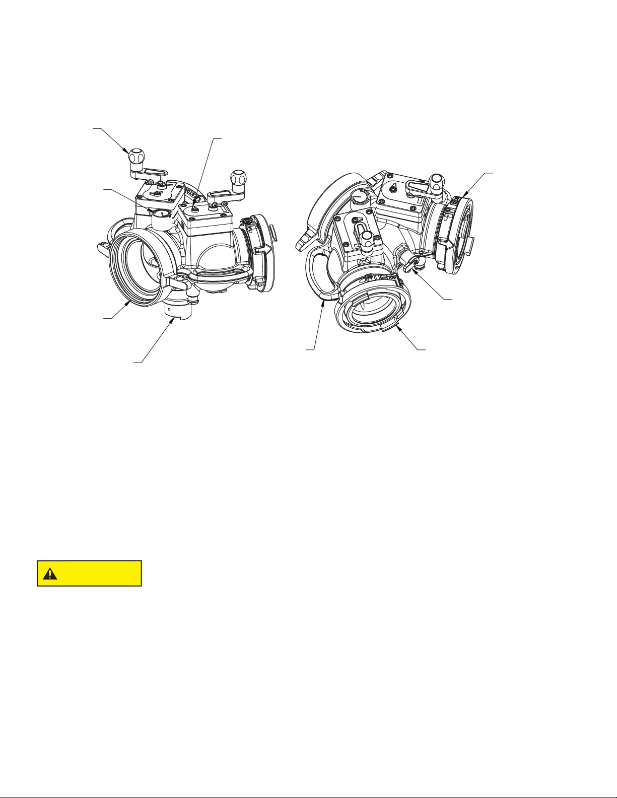
3.1 PARTS IDENTIFICATION AND MODELS
CRANK
VALVE POSITION INDICATOR
PRESSURE
GAUGE
SIDE A
COUPLING
CARRYING HANDLE
SIDE B
COUPLING
PRESSURE
RELIEF VALVE
3.2 SPECIFICATIONS
Dual LDH outlet waterway size (at valve seat): 3.65” (93mm)
Inlet waterway size: 5.5” for 6” Storz and 6” Threaded couplings, 4.5” for all other couplings.
LDH Valve meets NFPA 1965 slow close requirement.
Maximum Operating Pressure: 300 psi (20 bar)
Hydrostatic Proof Test Pressure: 900 psi (62 bar)
Temperature Rating*: -25°F to 135°F (-32°C to 57°C)
*For temperatures below 32°F (0°C), valves must be drained after use to avoid damage. See section
SIDE B
COUPLING
AIR VENT & DRAIN
2.0 SAFTEY.
3.3 CORROSION
Hose couplings are attached using polymer bearing rings which provide electrical insulation to help galvanic corrosion. The parts are
then hard anodized, and fi nally powder coated, inside and out, to help prevent corrosion. The effects of corrosion can be minimized
by good maintenance practice. See section 6.0 MAINTENANCE.
Dissimilar metals coupled together can cause galvanic corrosion that can result in the inability
CAUTION
to unscrew the threads or complete loss of thread engagement over time. Per NFPA 1962
(1998 edition), if dissimilar metals are left coupled together, an anti-corrosive lubricant should
be applied to the threads. Also the couplings should be disconnected and inspected at least
quarterly.
3.4 USE WITH SALT WATER
Use with salt water is permissible provided valve is thoroughly cleaned with fresh water after each use. The service life of the valve
may be shortened due to the effects of corrosion and is not covered under warranty.
©Copyright Task Force Tips, Inc. 2012 LIA-540 April 16, 2012 Rev00
4

4.0 INSTALLATION
4.1 CHANGING OFFSET OF CRANK HANDLE
When equipped with a crank handle, two offset positions are
available to adjust the swing radius of the crank and knob as
shown in the fi gure below. The longer offset position offers
reduced effort to operate the valve. The shorter offset is available
to avoid interference with other equipment. To change the offset,
remove the two ¼”-20 x 1/2” button head cap screws from crank.
Place crank in desired position and replace screws.
REINSTALL CRANK
IN THIS HOLE
IF SHORTER SWING
IS DESIRED
4.2 STORZ SUCTION GASKET REQUEST
If your application of this product requires drafting, you may need a suction gasket. Please call 1-800-348-2686 to receive a free
suction gasket by mail.
Part Numbers: 4” Storz- item#A4216, 5” Storz – item #A4221, 6” Storz - item #A4226
5.0 USE
5.1 VALVE POSITION INDICATOR
To open the valve turn the crank until the valve position indicator says “OPEN”. T o close the valve turn the valve crank the opposite
way until the valve position indicator says “CLOSED”.
5.2 AIR VENT AND WATER DRAIN
This device is equipped with an air vent/drain which will allow the air to escape from the valve when the inlet is charged. The air vent/
drain is opened by turning the knob counter-clockwise and closed by turning it clockwise.
To drain the water out of the valve after use, open the air vent/drain. A ½” diameter tube may be used to direct the drained water
away from the device.
Loss of prime can interrupt water fl ow and cause injury or death. Always bleed out air with air
DANGER
vent/drain to prevent possible loss of prime.
5.3 PRESSURE RELIEF VALVE
This device may be equipped with a pressure relief valve that can be set to any pressure between 50 and 200 psi. Its function is to
protect the pump and supply hose from excess pressure.
LIA-520 Pressure Relief Valve Instructions for Safe Operation and Maintenance.
See
5.4 SUCTION SCREEN
This device may be equipped with a suction screen to catch debris larger than 3/8” diameter in the waterway. See chart in section
5.6 Pressure Loss to determine additional loss caused by screen. To add or replace a suction screen, order TFT Part #A1410-KIT
for 4.5” waterway couplings or A1411-KIT for 6” waterway couplings.
5.5 PRESSURE LOSS
PRESSURE LOSS
0 1000 2000 3000 4000 5000 6000 7000
10
9
8
7
6
5
4
LOSS (PSI)
3
2
1
0
0 200 400 600 800 1000 1200 1400 1600 1800 2000
FLOW (GPM)
(LPM)
2
1.5
1
0.5
0
(BAR)
©Copyright Task Force Tips, Inc. 2012 LIA-540 April 16, 2012 Rev00
5

6.0 MAINTENANCE
This valve should be disconnected, cleaned and visually inspected inside and out at least quarterly for proper function per NFPA 1962
Section 8.2, or as water quality and use may require. Moving parts such as handles, valve ball and couplings should be checked for
smooth and free operation. Seals shall be greased as needed with silicone-based grease such as Dow Corning 112. Any scrapes
that expose bare aluminum should be cleaned and touched up with enamel paint such as Rust-Oleum.
In particular assure that:
• There is no damage such as cracks or dents
• There is no corrosion
• The waterway is clear of obstructions
• Pressure Relief Valve setting indications are readable
• The Pressure Relief Valve opens at the set pressure
Replace any missing or damaged parts before returning to service. Any repaired device must be tested before being placed in
service.
Any alterations to the device and its markings could diminish safety and constitute a misuse this
CAUTION
product.
©Copyright Task Force Tips, Inc. 2012 LIA-540 April 16, 2012 Rev00
6

7.0 EXPLODED VIEWS & PARTS LISTS
7.1 VALVE
2
3
6
20
4
7
5
8
9
10
11
12
21
1
13
14
15
16
17
13
19
ITEM DESCRIPTION QTY PART#
1 BODY 1 A2009
BODY A2008
2 GAGE 300PSI 1 AY176
3 SPRING 1 X165
4 GAGE PROTECTOR 1 AY170
5 BUSHING 1 VFHB4MX2F
6 3/8-16 X 1.75" SOCKET SCREW 1 VT37-16SH1.7
7 GEARBOX SUBASSEMBLY 1 A1633
GEARBOX SUBASSEMBLY 1 A1633R
8 O-RING 128 2 VO-128
9 DRAIN VALVE 1 A1621
10 HALF BALL 2 A1043S
18
ITEM DESCRIPTION QTY PART #
11 SEAL 2 A1520
12 MATE 2 A201*
13 1/4-20 X 1/2" SET SCREW 3 VT25-20SS500
14 O-RING 115 2 VO-115
15 TRUNNION 2 AY357
16 FOOT 4 A2037
17 O-RING 150 1 VO-150
18 PRV PLUG 1 A2155
19 PRV 1 A1755
20 SINGLE SIDE COUPLING 1 SEE CHART
21 DUAL SIDE COUPLING 2 SEE CHART
©Copyright Task Force Tips, Inc. 2012 LIA-540 April 16, 2012 Rev00
7

7.2 PARALLEL SHAFT GEARBOX
1
2
3
4
5
6
7
8
9
10
11
12
13
14
15
16
17
21
22
23
24
25
26
27
28
ITEM DESCRIPTION QTY PART #
KNOB 1 A1512
1
1/4-20 X 1/2 BUTTON HEAD SCREW 2 VT25-20BH500
2
CRANK 1 A1559
3
CRANK BUSHING 1 A1547
4
WASHER 1 VW812X406-65
5
3/8-16 X 1-1/2 BUTTON HEAD SCREW 1 VT37-16BH1.5
6
GEAR BOX 1 A1550
7
O-RING-116 1 VO-116
8
SPACER 1 A1556
9
DRIVE SHAFT 1 A1555
10
NYLON BUSHING 1 AY307
11
GEAR BUSHING 1 A1548
12
DOUBLE GEAR 1 A1554
13
BUSHING 1 A1549
14
INNER TRUNNION 1 A1553
15
INNER TRUNNION 1 A1553R
DOWEL PIN 2 VP312X.50
16
O-RING-154 1 VO-154
17
SUBPLATE 1 A1551
18
O-RING-028 1 VO-028
19
INNER BUSHING 1 A1552
20
FOLDING HANDLE LABEL 1 AY342
21
10-24 X 3/8 BUTTON HEAD SCREW 1 VT10-24BH500
22
WASHER 1 VW500X203-60
23
POSITION INDICATOR 1 A1558
24
NAME LABEL 1 A1550L
25
NAME LABEL RIGHT 1 A1550R
O-RING-206 1 VO-206
26
INDICATOR GEAR 1 A1557
27
O-RING-214 1 VO-214
28
1/4-20 X 3/4 SOCKET HEAD SCREW 1 VT25-20SH750
29
18
19
29
20
©Copyright Task Force Tips, Inc. 2012 LIA-540 April 16, 2012 Rev00
8

7.3 PRESSURE RELIEF VALVE
1
2
5
7
8
15
9
10
16
21
11
12
20
4
ITEM DESCRIPTION QTY PART#
1 1/2-13 X 1.0 SCREW 1 VT50-13BH1.0
2 DEBRIS WASHER 1 A1169
3 TURNED HOUSING 1 A2156
4 O-RING-232 1 VO-232
5 VALVE SEAT PRV 1 A1168
6 PISTON 1 A1160
7 QUAD-RING 222 2 VOQ-4222
8 SPRING SEAT 1 A1166
9 RELIEF SPRING 1 A1170
10 SMALLEY RING 1 V4210
11 ADJUSTING SCREW 1 A1167
12 SPRING HOUSING 200 MAX 1 A1164
13 SET SCREW PLUG 1 A1162
14 5/16-18 X 1/4 SET SCREW 1 VT31-18SS250
©Copyright Task Force Tips, Inc. 2012 LIA-540 April 16, 2012 Rev00
9

7.4 BLEEDER OPTION
1
2
6
5
4
ITEM DESCRIPTION QTY PART#
1 1/2" BARB X 1/4"NPTM NIPPLE 1 XX329
2 FOLLOWER 1 U251
3 3/8-24 X 3/8 DOG POINT 1 H515
4 DRAIN HOUSING 1 A1543
5 O-RING 115 2 VO-115
6 DRAIN SLEEVE 1 A1541
7 O-RING-110 1 VO-110
8 DRAIN LEVER 1 A1542
3
5
8
7
©Copyright Task Force Tips, Inc. 2012 LIA-540 April 16, 2012 Rev00
10

7.5 SIDE A (SINGLE SIDE) COUPLING COMPONENTS
QTY DESCRIPTION 4.0" STORZ 5.0" STORZ 6.0" STORZ 4.0" FEMALE LH4.5" FEMALE LH5.0" FEMALE LH6.0" FEMALE
1 INLET MATE A2115 A2115 -- A2115 A2116 A2116 -1 O-RING VO-252 VO-252 -- VO-252 VO-252 VO-252 -1 SOCKET HEAD SCREW VT25-20SH500 VT25-20SH500 -- VT25-20SH500 VT25-20SH500 VT25-20SH500 -1 GASKET -- -- -- V3198 V3210 V3220 V3240
1 INLET COUPLING A4124 A4125 A4326 A4562N A4568NR A4573NT A4575NX
1 PLASTIC STRIP A1292 A1291 A1293 A1291 A1293 A1293 A1293
1 CUP SEAL A1597 A1596 A1594 -- -- -- -1 LOCKOUT SCREW A1294 A1294 A1294 -- -- -- -1 NFS RING -- -- -- A4561 -- -- A4576
1 O-RING -- -- -- VO-248 -- -- VO-254
1 MATE PSM4.25 X PSF5.25 A4730 -- -- -- -- -- -1 CUP SEAL A1596 -- -- -- -- -- -1 PORT COVER A1298 -- -- -- -- -- -1 PLASTIC STRIP A1291 -- -- -- -- -- --
7.6 SIDE B (DUAL SIDE) COMPONENTS
QTY DESCRIPTION 4.0" STORZ 5.0" STORZ 6.0" STORZ 4.0" MALE 4.5" MALE 5.0" MALE 6.0" MALE
1 OUTLET MATE A2015 A2016 A2016 A2016 A2016 A2016 A2016
1 CUP SEAL A1597 A1596 A1596 A1596 A1596 A1596 A1596
1 PLASTIC STRIP A1292 A1291 A1291 A1291 A1291 A1291 A1291
1 LOCKOUT SCREW A1294 A1294 A1294 A1294 A1294 A1294 A1294
1 OUTLET COUPLING A4124 A4125 A4126 A4620N A4625N A4630N A4635N
LH
©Copyright Task Force Tips, Inc. 2012 LIA-540 April 16, 2012 Rev00
11

8.0 ANSWERS TO YOUR QUESTIONS
We appreciate the opportunity of serving you and making your job easier. If you have any problems or questions, our toll-free
“Hydraulics Hotline”, 800-348-2686, is normally available to you 24 hours a day, 7 days a week.
9.0 WARRANTY
Task Force Tips, Inc., 3701 Industrial Way, Valparaiso, Indiana 46383-9327 USA (“TFT”) warrants to the original purchaser of its
LDH GA TED WYE (“equipment”), and to anyone to whom it is transferred, that the equipment shall be free from defects in material
and workmanship during the fi ve (5) year period from the date of purchase.
TFT’s obligation under this warranty is specifi cally limited to replacing or repairing the equipment (or its parts) which are shown by
TFT’s examination to be in a defective condition attributable to TFT. To qualify for this limited warranty, the claimant must return
the equipment to TFT, at 3701 Industrial Way, Valparaiso, Indiana 46383-9327 USA, within a reasonable time after discovery of
the defect. TFT will examine the equipment. If TFT determines that there is a defect attributable to it, TFT will correct the problem
within a reasonable time. If the equipment is covered by this limited warranty, TFT will assume the expenses of repair.
If any defect attributable to TFT under this limited warranty cannot be reasonably cured by repair or replacement, TFT may elect to
refund the purchase price of the equipment, less reasonable depreciation, in complete discharge of its obligations under this limited
warranty. If TFT makes this election, claimant shall return the equipment to TFT free and clear of any liens and encumbrances.
This is a limited warranty. The original purchaser of the equipment, any person to whom it is transferred, and any person who is
an intended or unintended benefi ciary of the equipment, shall not be entitled to recover from TFT any consequential or incidental
damages for injury to person and/or property resulting from any defective equipment manufactured or assembled by TFT. It is
agreed and understood that the price stated for the equipment is in part consideration for limiting TFT’s liability. Some states do not
allow the exclusion or limitation of incidental or consequential damages, so the above may not apply to you.
TFT shall have no obligation under this limited warranty if the equipment is, or has been, misused or neglected (including failure to
provide reasonable maintenance) or if there have been accidents to the equipment or if it has been repaired or altered by someone
else.
THIS IS A LIMITED EXPRESS WARRANTY ONLY. TFT EXPRESSLY DISCLAIMS WITH RESPECT TO THE EQUIPMENT
ALL IMPLIED WARRANTIES OF MERCHANTABILITY AND ALL IMPLIED WARRANTIES OF FITNESS FOR A PARTICULAR
PURPOSE. THERE IS NO WARRANTY OF ANY NATURE MADE BY TFT BEYOND THAT STATED IN THIS DOCUMENT.
This limited warranty gives you specifi c legal rights, and you may also have other rights which vary from state to state.
TASK FORCE TIPS, INC.
MADE IN USA • www.tft.com
©Copyright Task Force Tips, Inc. 2012 LIA-540 April 16, 2012 Rev00
3701 Innovation Way, Valparaiso, IN 46383-9327 USA
800-348-2686 • 219- 462-6161 • Fax 219-464-7155
 Loading...