

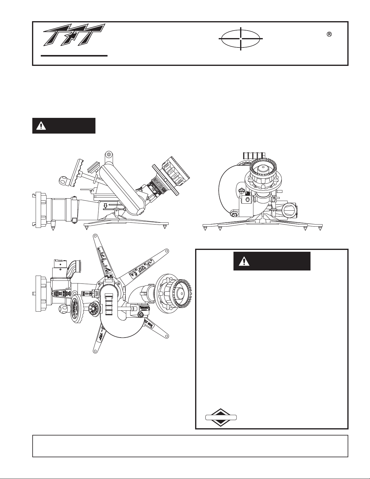
Task Force Tips Crossfire Monitor, Stow-A-Way 800 Base Instructions For Safe Operation And Maintenance
Page 1
®
TASK FORCE TIPS
FIRE FIGHTING EQUIPMENT
®
MANUAL:
WITH STOW-A-WAY 800 BASE
CROSSFIRE
INSTRUCTIONS FOR SAFE OPERATION AND MAINTENANCE
This instruction manual is intended to familiarize firefighters and maintenance personnel with the operation, servicing, and
safety procedures associatedwith the CROSSFIRE portable/deck gun.
This manual shouldbe kept availableto all operating and maintenance personnel.
Read instruction manual before use. Operation of this device without understanding
DANGER
the manual and receiving proper training is a misuse of this equipment. A person who
has not read and understood all operating and safety instructions, is not qualified to
operate the CROSSFIRE portable/deck gun.
SERIAL#:SERIAL#:
MODEL#:XFT-NJMODEL#:XFT-NJ
TFTX-XXXXXXTFTX-XXXXXX
Maximum recommended flow:
1250 GPM (5000 L/min)
on truck mount adaptor,
800 GPM (3000 L/min)
on portable base.
Maximum recommended
inlet pressure is 175 psi (12 bar).
DANGER
PERSONAL RESPONSIBILITY CODE
The member companies of FEMSA that provide emergency response
equipment and services want responders to know and understand the
following:
1. Firefighting and Emergency Response are inherently dangerous
activities requiring proper training in their hazards and the use of extreme
caution at all times.
2. It is your responsibility to read and understand any user's instructions,
including purpose and limitations, provided with any piece of equipment
you may be called upon to use.
3. It is your responsibility to know that you have been properly trained in
Firefighting and /or Emergency Response and in the use, precautions,
and care of any equipment you may be called upon to use.
4. It is your responsibility to be in proper physical condition and to maintain
the personal skill level required to operate any equipment you may be
called upon to use.
5. It is your responsibility to know that your equipment is in operable
condition and has been maintained in accordance with the
manufacturer’s instructions.
6. Failure to follow these guidelines may result in death, burns or other
severe injury.
FEMSA
Fire and Emergency Manufacturers and Services Association, Inc.
P.O. Box 147, Lynnfield, MA 01940 • www.FEMSA.org
TASK FORCE TIPS, Inc.
MADE IN USA •www.tft.com
©Copyright Task Force Tips, Inc. 1999-2011
3701 Innovation Way, Valparaiso, IN 46383-9327 USA
800-348-2686 • 219-462-6161 • Fax 219-464-7155
LIX-040 September 13, 2011 Rev05
Page 2
TABLE OF CONTENTS
1.0 MEANING OF SAFETY SIGNAL WORDS
2.0 SAFETY
3.0 GENERAL INFORMATION
3.1 PART IDENTIFICATION
4.0 CROSSFIRE® DEPLOYMENT
4.1 QUICK CONNECT SWIVEL JOINT
4.2 INSTALLING MONITOR ON BASE
.3 REMOVING MONITOR TOP FROM BASE
4.4 SIDE-TO-SIDE ROTATION & ROTATION
LOCK
4.5 ELEVATION CONTROL & STOP PIN
4.6 AUTOMATIC DRAIN
4.7 TRUCK MOUNT BASE
4.8 TRUCK MOUNTING OF THE PORTABLE
BASE
4.9 CROSSFIRE® USAGE
4.10 FLOWS & PRESSURES
4.10.1 STACKED TIPS
4.10.2 AUTOMATIC MASTER STREAM
NOZZLES
4.10.3 STREAM STRAIGHTENERS
4.11 TRANSPORTING MONITOR ON TRUCK
MOUNT BASE
5.0 STOW-A-WAY 800 BASE
5.1 SITE SELECTION
5.2 EXTENDING PORTABLE BASE LEGS
5.3 RETRACTING PORTABLE BASE LEGS
5.4 PORTABLE BASE LEG SPIKES
5.5 PORTABLE BASE ANCHORING
5.6 ADDING A FLOW SAFETY VALVE
5.7 HOSE CONNECTION
5.8 PORTABLE BASE STORAGE
5.9 PRESSURE RELIEF OPTION
5.10 PRESSURE RELIEF VALVE SETTING
6.0 MAINTENANCE
6.1 GREASE WORM GEAR
6.2 PERFORMANCE TESTING
7.0 SPECIFICATIONS
8.0 DRAWINGS AND PARTS LIST
9.0 WARRANTY - CROSSFIRE SERIES
10.0 INSPECTION CHECKLIST
1.0 MEANING OF SAFETY SIGNAL WORDS
A safety related message is identified by a safety alert symbol and a signal word to indicate the level of risk involved with a particular
hazard. Per ANSI standard Z535.4-1998 the definitionsof the threesignal words are as follows:
DANGER indicates an imminently hazardous situation which, if not avoided, will result in death or
DANGER
WARNING
CAUTION
serious injury.
WARNING indicates a potentially hazardoussituation which, if not avoided, could result in death or
serious injury.
CAUTION indicates a potentially hazardous situation which, if not avoided, may result in minor or
moderate injury.
2.0 SAFETY
The operation of this monitor, particularly with the portable base can be dangerous.
The following must be observed at all times.
Low nozzle elevation angles can cause portable monitors to slide or lift off the ground which can
DANGER
DANGER
result in injury or death. Do not operate the monitor on the portable base below the elevation safety
stop.
An out of control monitor can cause injury or death. To reduce risk of instability, do not attempt to
move the portablemonitor with waterflowing.
WARNING
Injury can occur from an inadequately supported monitor. When the monitor is used on a truck the
mounting must be capable of supporting 900 lbs (400 KG) of nozzle reaction force. Note: the
storage bracket is intended for storage of the monitor only. It is not strong enough to withstand the
forces of monitor operation. Flanges and pipe made from plastic are inadequate for monitor
mounting and mustnot be used.
2
Page 3
WARNING
WARNING
WARNING
WARNING
A sliding monitorcan cause injury. To protectagainst sliding:
• make surethe base legs are lockedin position withall leg spikesin contact with the ground.
• securely tiethe monitor to an objectcapable of withstanding900 lbs (400 kg) of force.
• use additionaltie downs on hard surfacessuch as concrete,asphalt, and metal.
• avoid liftingthe monitor when moving thehoses around it.
This equipment is intended for use by trained personnel for firefighting. Their use for other
purposes may involve hazards not addressed by this manual. Seek appropriate guidance and
training to reducerisk of injury.
Some volatile liquidscan be ignitedby static discharge. Static build-upcan occur from:
Electrochemical separation of charge as water drains through low conductivity, refined
!
products.
Applying foam over a low conductivity liquid of sufficient depth to retain the charge created as
!
the foam blanketdrains.
Streaming currents aswater or foamis introduced into the storagetank.
!
Water is a conductor of electricity. Application of water solutions on high voltage equipment can
cause injury or death by electrocution. The amount of current that may be carried back to the nozzle
will depend onthe following factors:
Voltage of the lineor equipment
!
Distance from thenozzle to theline or equipment
!
Size of thestream
!
Whether the streamis solid orbroken
!
Purity of thewater
!
2
1
1
Electrostatic Hazards of Foam Blanketing Operations by Peter Howels. Industrial Fire Safety July/August 1993
2
The Fire Fighter and Electrical Equipment, The University of Michigan Extension Service, Fourth Printing 1983. Page 47.
Master stream flows are very powerful and capable of causing injury and property damage. Make
CAUTION
CAUTION
CAUTION
sure the monitor is securely attached to the base and pointing in a safe direction before water to the
monitor is turnedon. Use carein directing the stream.
Nozzle must be properly connected. Mismatched or damaged threads may cause nozzle to leak or
uncouple under pressureand could causeinjury.
Do not couple aluminum to brass. Dissimilar metals coupled together can cause galvanic
corrosion that canresult in inabilityto unscrew threads or completeloss of threadengagement.
3.0 GENERAL INFORMATION
The CROSSFIRE monitor is the most rugged and innovative deck/portable master stream device ever offered to the fire service.
Attachment of theCROSSFIRE to thebase is quick, easy, positive, and can be visually verified.The release mechanismis locked out by
water pressure. The rotation lockis a simple lever whichsecurely holds the CROSSFIRE monitor in position. An automatic drainallows
water to drainfrom the monitor when notin use.
3
Page 4
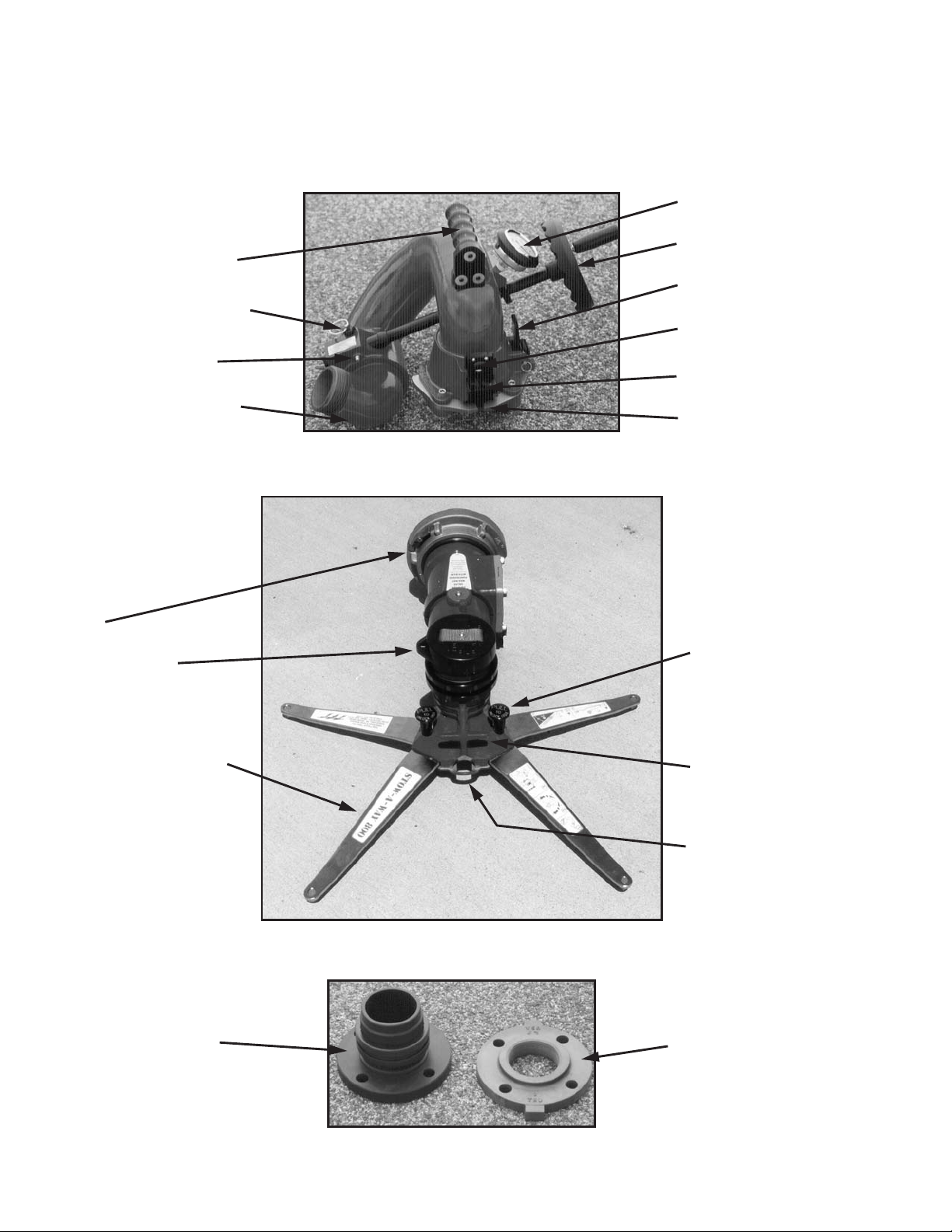
3.1 CROSSFIRE PART IDENTIFICATION
Figures 3.1.1, 3.1.2, & 3.1.3 show the CROSSFIRE monitor, STOW-A-WAY 800 portable base, truck mount adapter and identifies the
various parts andcontrols.
CROSSFIRE
MONITOR TOP
Carrying Handle
Elevation Pin Stop
Grease Fitting
Automatic Drain
STOW-A-WAY 800
BASE
Inlet
Anchor Strap
& Storage Cover
Pressure Gauge
Elevation Control
Rotation Lock
Safety Plunger
Slide Bar
Pawls
Figure 3.1.1
Leg Lock Knob
Stainless Steel Leg
TRUCK MOUNT
ADAPTOR
Carrying Handle
Anchor
Attachment Point
Figure 3.1.2
COMPANION
FLANGE
Figure 3.1.3
4
Page 5
4.0 CROSSFIRE DEPLOYMENT
The CROSSFIRE monitor can be used on either a truck mount adaptor, Extend-A-Gun or portable base. Installation on either base
makes use ofa quick connect swivel joint.The use of each base and thequick connect jointis explained in the following sections.
4.1 QUICK CONNECT SWIVEL JOINT
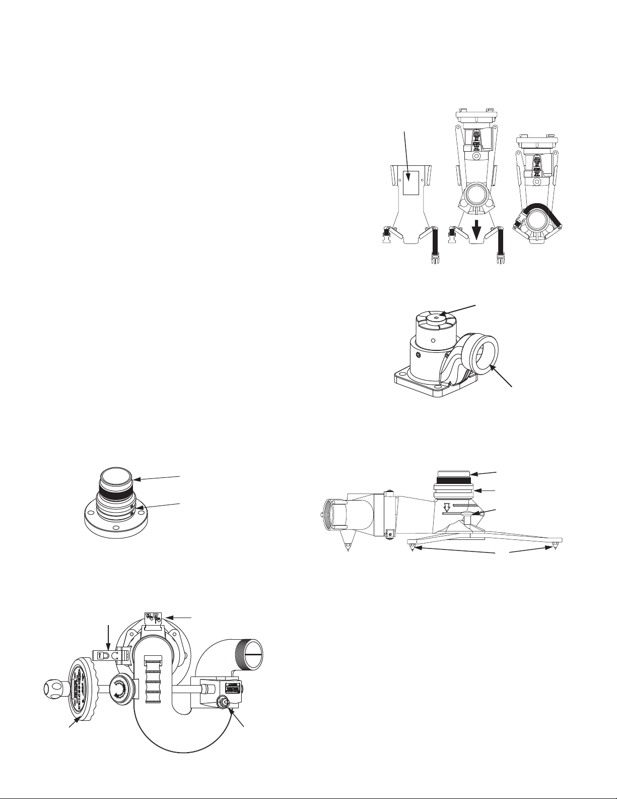
Two pawls, actuated by the slide bar, engage in the base swivel to make the quick connect joint. A safety plunger engages in the slide
bar to preventaccidental unlocking of the slidebar when the monitor is under pressure.
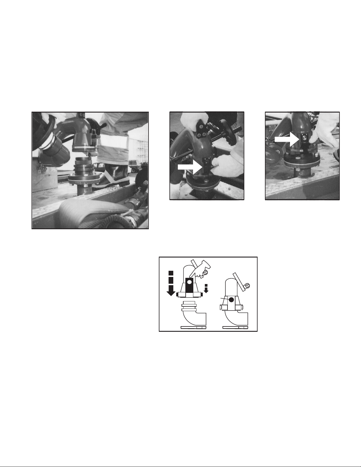
4.2 INSTALLING MONITOR ON BASE
To install the monitoron either thetruck mount flange or portable base: Referto figures 4.2.1,4.2.2, & 4.2.3.
Figure 4.2.1 Figure 4.2.2 Figure 4.2.3
B C
A
A) Turn elevation handwheel to make sure the
elevation of the nozzle is above the 35° safety stop.
Verify that the elevation stop pin is down and
engaged.
Make sure the slide bar is in the up position.
Slide bar up, safety
plunger is not engaged.
B) Hold the monitor by the top
carrying handle, position
monitor over base and slide
straight down.
A
Slide bar locked, safety
plunger is engaged.
C) Push the slide bar down,
watch the pawls engage the
groove in the base and the
safety plunger engage in the
hole in the slide bar.
B
C
4.3 REMOVING MONITOR TOP FROM BASE
To remove the monitorfrom it’s base:
• Stop allwater flow.
• Depress thesafety plunger and lift theslide bar which will disengage the springloaded pawls fromthe groove in the base.
• Lift themonitor straight up off thebase by the handle on top ofthe monitor.
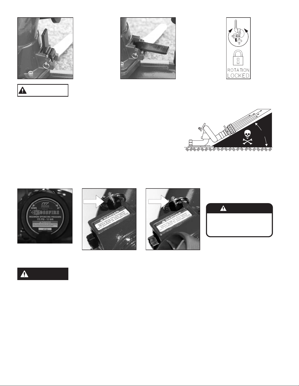
4.4 SIDE-TO-SIDE ROTATION AND ROTATION LOCK
Side-to-side rotation is accomplished by rotating the monitor on its base. The rotational position can be locked by moving the rotation
lock lever to its down position as shown in Figures 4.4.1 & 4.4.2. Before the monitor is removed from the base, the rotation lock should
be manually disengaged. A small spring holds the rotational lock in the unlocked position. When not rotating the monitor on the base,
keep the rotationlock locked.
5
Page 6
WARNING
Figure 4.4.1
Unlocked
A sliding monitor can cause injury. When used on a portable base, keep the horizontal
angle between the water stream and the anchor strap as small as possible. At large
angles the base can slide in an arc around the anchor point.
Figure 4.4.2
Locked
4.5 ELEVATION CONTROL AND STOP PIN
When a nozzle is flowing water the reaction force acts in a straight line that is directly
opposite the water flowing out the end of the nozzle. If a nozzle on a monitor on a
portable base is pointed straight up, all of the reaction force is directed straight down
and there is no sideways force that can cause the base to slide. As the nozzle is
angled downward at the same flow, the reaction force remains the same, but some of
that force becomes a force acting sideways and some acts in a downward direction.
When the nozzle is at an angle of 45° the force acting sideways is equal to the force
acting downward on the base. As the elevation angle of the nozzle is lowered the
sideways force increases while the downward force decreases. At an angle of 35°, (the angle at the elevation safety stop),
approximately 82% of the nozzle reaction forceis acting sideways on the base. Whenthe nozzle is at a zero degree angle, with respect
to the base, the entire reaction force is acting sideways on thebase and there is no downward force atall. The lower the elevation angle
of the nozzle,with respect to the base,the greater the force that causes sliding,and the morelikely sliding will occur.
35°
DANGER
Operating On Portable
Base Below This Stop
(pin pulled) Is Dangerous.
XL090
Figure 4.5.1
Elevaton control
Operating on a portable base below this safety stop is DANGEROUS. Do not operate
DANGER
When mounted on a truck base, the nozzle may be lowered below the 35° safety stop by pulling out the stop pin and rotating the
handwheel below the 35° stop. When the nozzle is raised back above 35°, the spring loaded stop pin will snap back into position
automatically limiting theelevation of the nozzle withrespect to the base to 35°.
4.6 AUTOMATIC DRAIN
An automatic drain empties water from a low point in the monitor piping to prevent freezing and help empty hose lines. The valve is
designed to close automatically when pressure in the monitor exceeds approximately 5 psi and open again when the pressure drops
to that point. When the automatic drain isnot desirable itmay be disabled. To disable thedrain valve refer to the exploded view on page
12 and followthe steps below:
1) Unscrew thedrain assembly (40, 41, 42,& 43) and remove the screw andwasher (42 &43)
2) Flip overthe rubber drain valve (41)so that the raised edge is againstthe face ofthe housing (40).
3) Reassemble.
on portable base below safety stop. Injury or death can occur if the monitor and base
slides or lifts off the ground.
Figure 4.5.2
Elevation stop pin out
Figure 4.5.3
Elevation stop pin in
6
Page 7
4.7 TRUCK MOUNT BASE
The CROSSFIRE® monitor may be used from a truck by using a truck mount adapter. The truck mount adapter can be bolted to the
riser pipe with a 3" ANSI 150# or 4" ANSI 150# companion flange and gasket using 5/8" bolts. It can also be screwed directly on a male
pipe thread. Use of pipe thread sealant is recommended. The riser must be supported to safely withstand a nozzle reaction force of up
to 900 lbs (400 KG). Make sure that no interference exists between the monitor and other deck mounted equipment in any direction.
See truck mountbase installation instructions for details,document #LIX-045.
A drain valve should be provided in the riser pipe which supplies the monitor. The riser should be drained immediately after each use
during cold weather to preventfreezing and possible damage. The monitor has anautomatic drain. If this drainhas been disabled (see
section 4.6), the monitor must be drained by lowering the nozzle below horizontal. Installation instructions are supplied with the truck
mount base.
4.8 TRUCK MOUNTING OF THE PORTABLE BASE
In some cases a user may not have a riser directly off of the pump that can be used for mounting the monitor. In this case it may be
desirable to supply the monitor with hose lines connected to the side discharge of the pumper. In these circumstances it is
recommended that the user purchase a Deck Mount Plate, TFT part XF400-KIT, from the manufacturer. Please call 1-800-348-2686 for
further information and advice concerningmounting alternatives. Installation instructions areshipped with this accessory. The storage
bracket, TFT part XF-B, for the base unit IS NOT STRONG ENOUGH to withstand the forces encountered with an operating monitor
and is notintended for this purpose.
4.9 CROSSFIRE® USAGE
Because of the arched trajectory of a fire stream, it is recommended that a spotter be used to accurately direct the stream from the
monitor. Master streamsflows are powerful and capable of injuryand damage toproperty. Use greatcare in directing the stream.
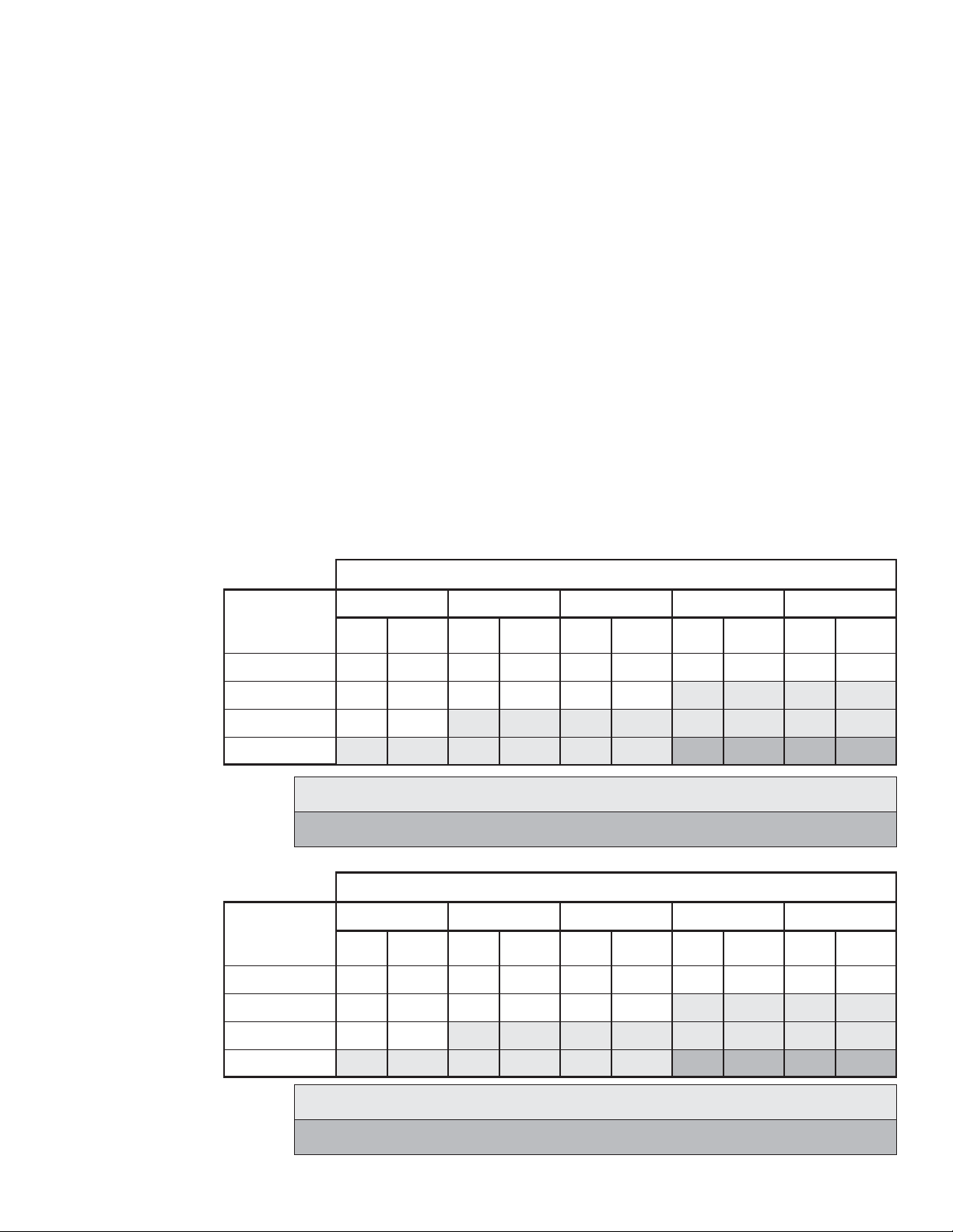
4.10 FLOWS & PRESSURES
The CROSSFIRE® monitor is designed for maximum flows of 1250 gpm (5000 l/min) on the truck mount adaptor, 800 gpm (3000 l/min)
on the STOW-A-WAYportable base anda maximum pressure of 175 psi (12bar). Do notexceed these limits.
4.10.1 STACKED TIPS
NOZZLE
DIAMETER
1-3/8"
1-1/2"
1-3/4"
NOZZLE
DIAMETER
NOZZLE PRESSURE
50 PSI
REACTION
FLOW
(GPM)
400
470
640
2"
840
Flow exceeds rating of portable base. Use only when monitor is truck mounted.
Flow exceeds rating of truck mounted monitor.
(LBS)
150
180
240
310
80 PSI
FLOW
(GPM)
500
600
810
1060
REACTION
(LBS)
240
280
380
500
100 PSI
FLOW
(GPM)
560
660
910
1190
REACTION
(LBS)
300
350
480
630
150 PSI
FLOW
(GPM)
680
810
1100
—
REACTION
(LBS)
440
520
712
—
NOZZLE PRESSURE
10 BAR
FLOW
(L/min)
2600
REACTION
(KG)
200
(MM)
35
3.5 BAR
FLOW
(L/min)
1500
REACTION
(KG)
70
5.5 BAR
FLOW
(L/min)
1900
REACTION
(KG)
110
7 BAR
FLOW
(L/min)
2200
REACTION
(KG)
140
175 PSI
FLOW
(GPM)
730
870
1190
—
12 BAR
FLOW
(L/min)
2800
REACTION
(LBS)
520
620
840
—
REACTION
(KG)
240
38
44
50
1800
2400
3100
Flow exceeds rating of portable base. Use only when monitor is truck mounted.
Flow exceeds rating of truck mounted monitor.
110
140
80
2300
3000
3900
130
170
220
2500
3400
4400
160
220
280
3000
4100
—
230
310
—
3300
4500
—
7
280
370
—
Page 8
4.10.2 AUTOMATIC MASTER STREAM NOZZLES
Automatic nozzles maintain a constant pressure by adjusting their opening to match the available flow. Consult the nozzle
manufacturer for maximum flow and pressure ratings. In all cases, do not exceed 1250 gpm (5000 l/min) or 175 psi (12 bar) on a truck
mounted monitor or800 gpm (3000 l/min) onthe STOW-A-WAYbase.
4.10.3 STREAM STRAIGHTENERS
Stream quality, especially with smooth bore nozzles, is generally improved with a stream straightener because the water must make
many bends passingthrough a monitor.
4.11 TRANSPORTING MONITOR ON TRUCK MOUNT BASE
If the monitor is to be transported on a truck mount base, the horizontal lock should be kept locked to keep the monitor from spinning
on its base. The rotational position can be locked by moving the rotation lock lever to its down position. The nozzle may be supported
by a bracketor pointed straight up.
5.0 STOW-A-WAY 800 BASE
The portable base allows the monitor to be positioned in places that are not accessible with a fire truck. The legs are made of stainless
spring steel and will flex when in use to compensate for small ground irregularities. It is intended for maximum flows of 800 gpm (3000
l/min).
5.1 SITE SELECTION
Safe operation of the monitor on the portable base begins with site selection. The site should be a safe distance from the fire yet within
reach of the nozzle stream. Select a flat even surface within 8 feet of a sturdy stationary object that can be used as an attachment point
for the anchorstrap. Set up the portablebase with the anchor point between theportable base anddesired target of the nozzle stream.
5.2 EXTENDING PORTABLE BASE LEGS
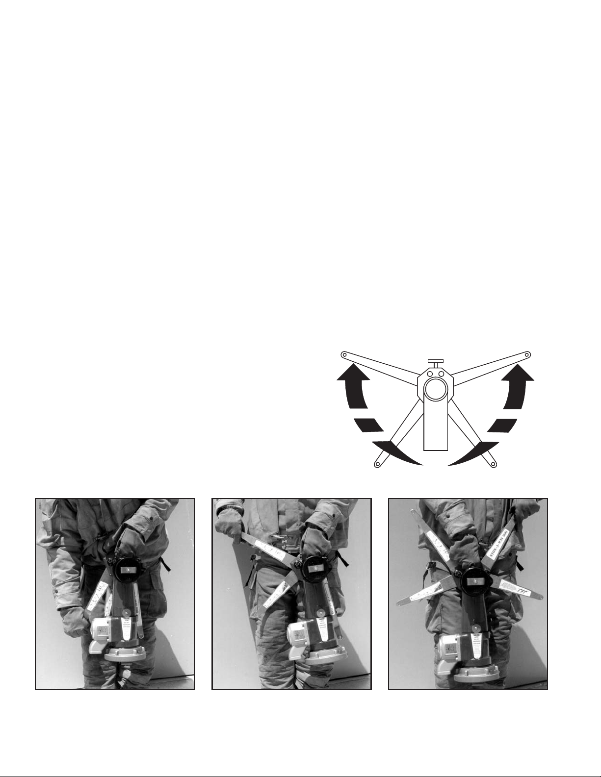
The portable baselegs are extended by followingthese steps:
(Refer to figures5.2.1, 5.2.2, & 5.2.3)
a) Hold the base carrying handle with one hand and grasp the end of one
of the longer legs with the other hand. Pull this leg away from the base
forward in an arc, until the locking pin engages. The locking pin is spring
loaded and automatically engages when the legs are in the correct
position. Watch the leg lock knob drop down, even with the lower band
on the base,indicated by an arrow.
b) Repeat procedure(a) to extend other setof legs.
c) Set portable base on even ground with all leg spikes in contact with the ground.
Figure 5.2.1
Hold base carrying handle and
grasp end of longer leg
Figure 5.2.2
One set of legs opened and
locked in position
8
Figure 5.2.3
Both sets of legs opened and
locked in position
Page 9
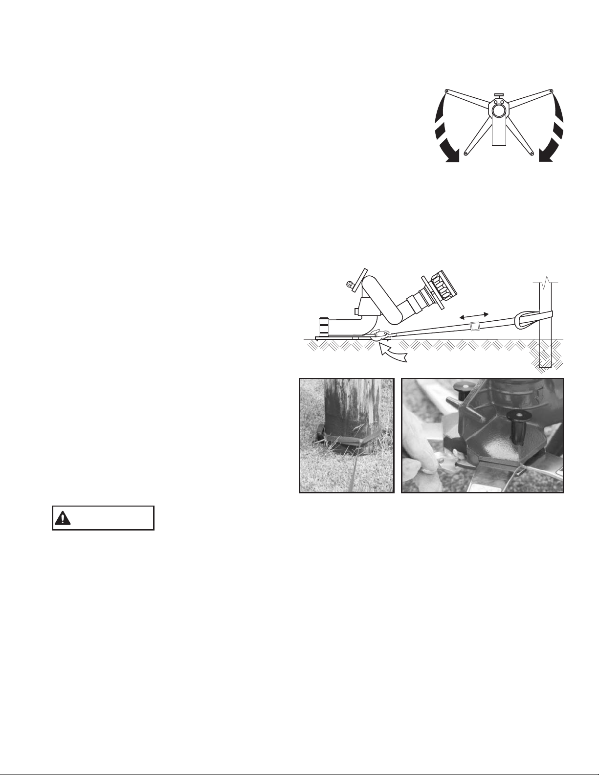
Lift off the storage cap and remove the anchor strap from inside the base. Keep the anchor strap near the monitor as it will be used to
anchor monitor beforeuse.
5.3 RETRACTING PORTABLE BASE LEGS
For carrying and storage, the legs areretracted as follows:
a) Pull up on one of the spring loaded leg lock knobs, grasp the forward leg, on the same
side, and push it, in an arc, towards the rear of the unit. The leg lock knob may be released
as soon as the front leg begins to move out of position. Continue to push until both legs
come in contactwith the rear stop.
b) Repeat procedure(a) to retract the otherlegs.
5.4 PORTABLE BASE LEG SPIKES
The STOW-A-WAY Base has5 tungsten carbidetipped spikes onthe legs andbase to resist sliding by digging into the surface the base
is sitting on. The amount of sideways force these spikes can withstand depends upon several factors, particularly, the amount of
downward and sideways force that is on the base and the hardness and texture of the surface the spikes are in contact with. At low
elevation angles it is difficult for these spikes to resist sliding. This is why the portable base must be well anchored. These spikes are
essential to safe operation of the monitor base and must be in contact with the ground at all times. Do not operate without first securing
the monitor with safety lines to prevent sliding. Set the monitor on an even surface so that all the spikes contact the ground. See section
6.0 for spikeinspection procedures.
5.5 PORTABLE BASE ANCHORING
Whenever the monitor is operated on the portable base, the
base must be anchored to a substantial immovable object.
An attachment point is provided on the front of the base for
this purpose. A strap, with a minimum breaking strength of
3000 lbs (1300 kg) of force, is supplied with the portable
base. A loop on the end of the strap may be placed over the
anchor point or the strap may be wrapped around an object,
such as a tree, and the snap end of the strap passed through
the loop and pulled tight. Keep the entire length of the strap
as close to the ground as possible. Snap the hook into the
hole in the front of the portable base below the carrying
handle. The length of the strap may be adjusted by the sliding
the buckle on the strap. If the strap is too short to reach a
suitable anchor, it may be extended with strong rope or chain.
Keep the distance between the base and anchor point as
short as possible.
A sliding monitor can cause injury. Remove all slack between the anchor and base
WARNING
At low nozzle elevation angles the base may also require additional anchoring.The ability of a single anchor to stop sliding is a function
of the horizontal angle between the strap and water stream. When the stream is in line with the anchor any sliding willbe arrested by the
anchor. As the horizontal angle increases between the anchor strap and the stream, the base can begin to slide in an arc around the
anchor point. Inthis situation multiple anchor pointsmay be required.
The strap should be stored inside the monitor base when not in use. The black rubber cap on the strap will hold the strap in the base
and protect thesealing surface of the quickconnect swivel joint.
before flowing water.
5.6 ADDING A FLOW SAFETY VALVE
The STOW-A-WAY 800 portable basedoes not containa flow safety valve.
A flow safety valve upgrade kit #XF500-KIT may be added to this portable base at any time to gain the features of the flow safety valve.
The kit maybe installed in the fieldor at the factory.
The flow safety valve reduces the flow area through the monitor by 90%., should the base loose contact with the ground for any reason.
In the reducedflow condition, the nozzle reactionis less thereby reducing the risk ofinjury.
9
Page 10
5.7 HOSE CONNECTION
Make the hose connection(s) to the portable base and extend the hose(s) straight back from the portable base at least 10 feet (3
meters). If only one inlet of a double inlet base be used, a clapper valve will automatically close off the other inlet. Use caution when
turning on the water to the monitor on the portable base. As the hose fills it will become stiff and may cause the monitor and portable
base to slideor tip or both. Openthe pumper valve to the monitor slowly.
XF-B
XF-B
STORAGE
5.8 PORTABLE BASE STORAGE
STORAGE
BRACKET
BRACKET
The portable base may be stored in a compartment, on the optional storage
bracket, TFT part number XF-B. This bracket is NOT designed to withstand the
reaction forces of an operating monitor stream. It is to be used for storage and
transportation only. The storage bracket may be mounted on a horizontal surface,
horizontally or vertically on a vertical surface, or on the underside of a horizontal
surface such as the top of a compartment. A strap helps hold the base on the
bracket. Mounting instructionsare supplied with the bracket.
5.9 PRESSURE RELIEF OPTION
The optional pressure relief valve on the single inlet portable base can be adjusted
to open between 50 and 200 psi. The pressure relief valve, TFT part A1820, is set at
the factory to open at 150 psi. To change the relief pressure refer to the label on the
1 2 3
bottom side of the pressure relief valve. A pressure relief valve can be added to the
single inlet portable base by removing the cover on the side of the base. For
additional information call800-348-2686.
Adjusting
Screw
5.10 PRESSURE RELIEF VALVE SETTING
To set the relief valve pressure turn the adjusting screw on the relief valve housing
until the surface of the screw is even with the desired pressure. Do not cap or plug
discharge opening.
Relief Valve
Discharge
Opening
6.0 MAINTENANCE
The CROSSFIRE® monitor and its base require little maintenance. The unit should be kept clean and free of dirt by flushing with water
after each use. All controls should be checked for freedom of movement and condition. Any inoperable or damaged part should be
repaired or replacedimmediately. Specific areasto check are as follows:
1
1
2
2
3
4
Truck Mount Base:
1) Sealing surfaceabove swivel joint must besmooth.
2) Swivel jointmust rotate freely.
3
2
4
40
20
SERIAL#:SERIAL#:
MODEL#:XFT-NJMODEL#:XFT-NJ
TFTX-XXXXXX
60
0
80
2
4
0
6
bar
psi
100
8
14
10
12
120
200
140
180
160
1
3
Portable Base:
1) Sealing surfaceabove swivel joint must besmooth.
2) Swivel jointmust rotate freely.
3) Legs andleg lock pins must movefreely and lock in position.
4) Leg spikesmust be sharp.
(replace if flatsat tip of spikes exceed1/16" diameter)
Monitor:
1) Handwheel mustrotate freely.
2) Elevation stoppin must return to safeposition.
3) Quick disconnectlatch and safety catch mustoperate freely.
4) Rotation lock must operate freely and keep monitor from rotating
when engaged.
1
2
10
Page 11

6.1 GREASE WORM GEAR
Turn the handwheel to move the nozzle to its highest elevation and pump grease (medium viscosity automotive) into
the fitting in the worm gear housing until excess appears.
6.2 PERFORMANCE TESTS
Performance tests shall be conducted on the Crossfire Monitor after a repair, or anytime a problem is reported to verify operation in
accordance with Task Force Tips test procedures. Consult factory for the procedure that corresponds to the model and the serial number
of the Monitor. Any equipment which fails the related test criteria should be removed from service immediately. Troubleshooting
guides are available with each test procedure or equipment can be returned to the factory for service and testing.
7.0 SPECIFICATIONS
Weight
Storage Volume
L-W- H
Height Above Truck Flange
Height Above Truck Deck (min)
Height Above Ground on Base
Line of Reaction Force Above Ground
Flow Area (minimum)
Maximum Flow
Maximum Pressure
Materials Used
Inlets Available
CROSSFIRE Monitor
17 lbs
6.7 kg
3
4060 in
3
.066m
20" x 14-1/2" x 14"
.51 x .37 x .36m
12-1/2 in
320mm
14 in
360mm
16-1/2 in
420mm
4in
100mm
2
8.3 in
5360mm
1250 GPM
5000 L/min
175 PSI
Cast Aluminum, Aluminum,
Stainless Steel
2
12 bar
One
STOW-A-WAY 800 Base*
20.7 lbs
9.4 kg
3
1620 in
.027m3
20"x9"x9"
.51 x .23 x .23m
NA
NA
NA
NA
2
8.3 in
5360mm
800 GPM
3000 L/min
175 PSI
Cast Aluminum, Aluminum,
Stainless Steel
Numerous Single & Double Inlets
2-1/2"-6"
2
12 bar
Dimensions shown for STOW-A-WAY 800 portable base with double inlet 2-1/2" model.
11
Page 12
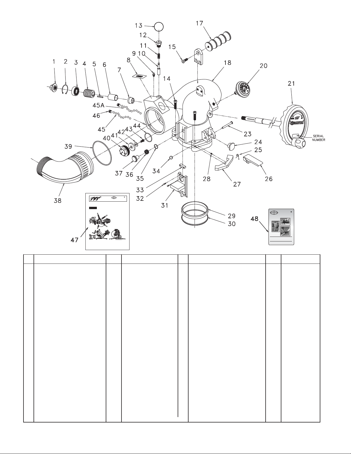
8.0 DRAWINGS & PARTS LIST
CROSSFIRE
®
Model No. XFT-NJ
CROSSFIRE
MANUAL:
MANUAL:
STOW-A-WAY800 BASE
WITH STOW-A-WAY800 BASE
WITH
INSTRUCTIONS FOR SAFE OPERATIONAND MAINTENANCEINSTRUCTIONS FOR SAFE OPERATIONAND MAINTENANCE
Read instruction manual before use. Operation of this device
Read instruction manual before use. Operation of this device
DANGER
understandingthe manual and receiving proper training is a
withoutunderstanding the manual and receiving proper training is a
without
misuse of this equipment. A person who has not read and
misuse of this equipment. A person who has not read and
understoodall operating and safety instructions, is not qualified to
understoodall operating and safety instructions, is not qualified to
theCROSSFIRE portable/deck gun.
operate
operatethe CROSSFIRE portable/deck gun.
Maximumrecommended
Maximumrecommended
is1250 GPM on
flowis 1250 GPM on
flow
mountadaptor, 800
truck
truckmount adaptor, 800
onportable base.
GPM
GPMon portable base.
Maximum
recommended
Maximumrecommended
pressureis 175 psi.
inlet
inletpressure is 175 psi.
Thisinstruction manual is intended to familiarize firefighters and maintenance
Thisinstruction manual is intended to familiarize firefighters and maintenance
personnelwith the operation, servicing, and safety procedures associatedwith the
personnelwith the operation, servicing, and safety procedures associatedwith the
R O SSF I R Epo r t a b l e / d e c kgu n .
CROSSFIRE portable/deck gun.
C
manualshould be kept available to all operating and maintenance personnel.
This
Thismanual should be kept available to all operating and maintenance personnel.
# DESCRIPTION QTY PART #
SHAFT NUT 1 X210
1
SNAP RING 1 VR4220
2
BEARING 1 VM4250
3
WORM WITH KEYWAY 1 X220
4
KEY 1/8 X 1.00 1 X225
5
BUSHING 1 X230
6
BOOT 1 X240
7
DANGER LABEL 1 XL090
8
11/4-28 GREASE FITTING 1 VT25-28ZERK
9
PULL PIN 1 X340
10
PULL PIN SPRING 1 X345
11
PULL PIN HOUSING 1 X350
12
KEY RING 1 VR4300
13
5/16-18 X 1-1/4 SHCS 2 VT31-18SH1.2
14
3/8-16X7/8SHCS 1 VT37-16SH875
15
PEG - CARRYING HANDLE 1 X362
17
BIG BEND/BELL ASSEMBLY 1 X800**
18
200 PSI/BAR GAGE/BUMPER 1 X823
20
HANDWHEEL ASSEMBLY 1 X810
21
ROTATION LOCK PIVOT 1 X180
23
ROTATION LOCK INSERT 1 X170
24
25 ROTATION LOCK SPRING 1 X152
26 ROTATION LOCK LEVER 1 X821
** NOTE: Specify desired color and hose thread at time of order.
CROSSFIRE
Thesafest, most versatile
masterstream device...Ever!
OPERATIONS MANUAL:
DVD SUPPLEMENT
ThisDVDis notintendedto replacethereading and
understandingofthe CROSSFIREoperationsmanual.
# DESCRIPTION QTY PART #
PAWL 2 X135
27
DETENT SPRING 2 H770
28
WEAR STRIP 1 X120
29
CUP SEAL .366 NITRILE 70A 1 X125
30
SLIDE BAR 1 X140
31
#6-32 X 1/4 BUTTON HEAD 2 VT06E32BH250
32
COVER 1 X142
33
CLEVIS PIN RETAINER 1 X137
34
O-RING-018 1 VO-018
35
PLUNGER WAVE SPRING 1 X165
36
SAFETY PLUNGER 1 X150
37
2.5 NH ELBOW/VANE ASSEMBLY 1 X339NJ**
38
O-RING-241 1 VO-241
39
DRAIN HOUSING 1 X375
40
DRAIN PLUG 1 X382
41
FLAT WASHER 1 VW687X281-50
42
1/4-28 X 1/2 BHCS 1 VT25-28BH500
43
O-RING 130 1 VO-130
44
5/16 SS BALLS 38 VB.312
45
5/16 TORLON BALLS 38 VB.312TO
45A
3/8-24 x 3/8 SOCKET SET 2 VT37F24SS312
46
MANUAL - CROSSFIRE WITH 1 LIX-040
47
STOW-A-WAY BASE
DVD - CROSSFIRE 1 LIX-200
48
12
Page 13
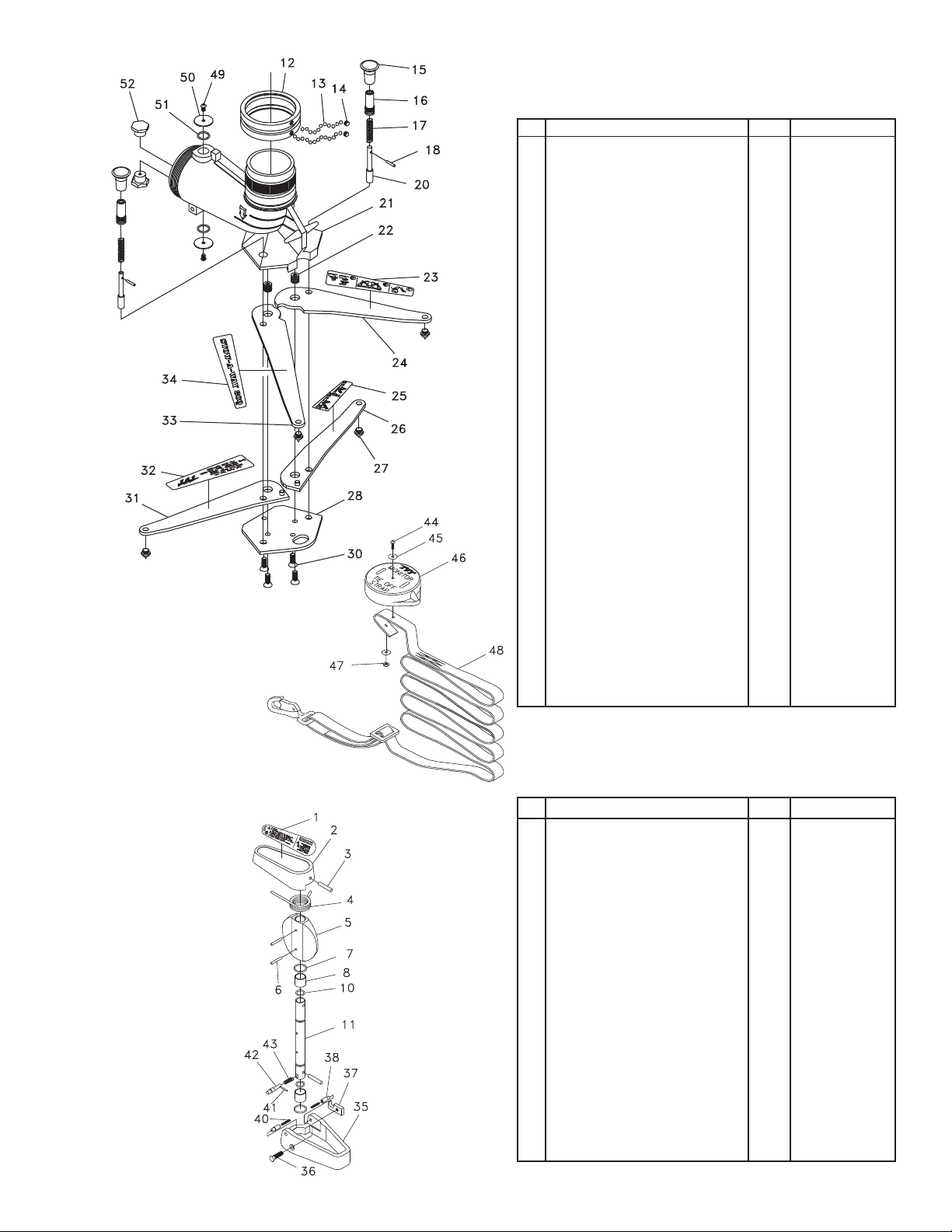
STOW-A-WAY 800
®
without Safety Valve
# DESCRIPTION QTY PART #
SWIVEL RING 1 X425
12
5/16 SS BALLS 76 VB.312
13
SWIVEL SCREW 2 X405
14
SHOT PIN KNOB 2 X430
15
KNOB BARREL 2 X440
16
SHOT PIN SPRING 2 X445
17
5/32 x 7/8 SPIROL PIN 2 V1900
18
SHOT PIN 2 X435
20
BASE 1 X420
21
BELLEVILLE WASHER 12 D07590
22
INSTRUCTION LEG LABEL 1-3 1 XL010
23
FRONT LEG - LEFT 1 X470L
24
INSTRUCTION LEG LABEL 4-5 1 XL020
25
REAR LEG - LEFT 1 X460L
26
SPIKE 4 X480
27
BOTTOM PLATE 1 X450
28
3/8-16 X 3/4 FLAT HEAD SHCS 4 VT37-16FH750
30
REAR LEG - RIGHT 1 X460R
31
TFT LEG LABEL 1 XL050
32
FRONT LEG - RIGHT 1 X470R
33
SAFE-TAK LEG LABEL 1 XL040
34
#10-32 x 3/4 BUTTON HEAD 1 VT10E32BH750
44
STAINLESS STEEL WASHER 18-8 2 V2038
45
STRAP CAP 1 X457
46
#10-32 HEX NUT 1 VT10-32NT
47
STRAP ASSEMBLY 1 RX455
48
1/4-28 X ½ BUTTONHEAD 2 VT25-28BH500
49
2.5" CLAPPER WASHER 2 X752
50
O-RING-118 2 VO-118
51
PLUG 2 X510
52
See
Section
5.6
13
XF500-KIT
VALVE UPGRADE KIT
# DESCRIPTION QTY PART #
SAFETY VALVE HANDLE LABEL 1 XL070
1
VALVE HANDLE 1 X540
2
1/4 x 1 3/8 SPIROL PIN 1 VP250X1.375H
3
TORSION SPRING 1 X560
4
BUTTERFLY 1 X550
5
5/32 x 1 1/8 SPIROL PIN 3 V1920
6
O-RING-118 2 VO-118
7
BUSHING 2 X565
8
O-RING-113 2 VO-113
10
VALVE SHAFT 1 X570
11
PADDLE 1 X530
35
1/4-20 x 7/8 FLAT HEAD 1 VT25E20FH875
36
WEAR PLATE 1 X585
37
PADDLE PIVOT 2 X590
38
PADDLE PIVOT SPRING 2 X575
40
3/32 x 1/2 SPIROL PIN 1 VP094X500H
41
TRIP PIN 1 X580
42
TRIP PIN SPRING 1 X582
43
Page 14
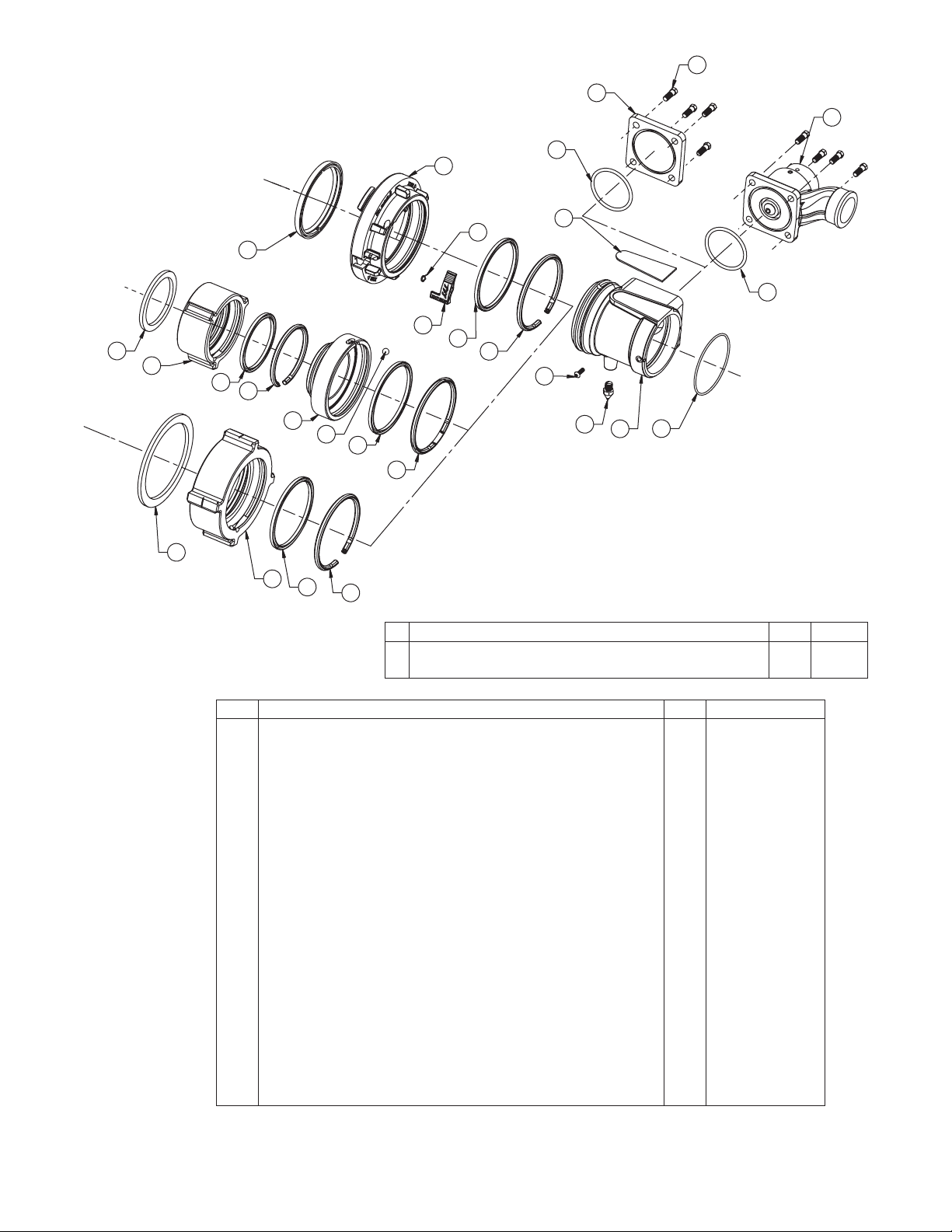
HIGH FLOW SINGLE INLET OPTION
15
16
14
18
27
38
37
40
36
31
35
39
33
24
32
23
22
17
21
20
19
26
25
24
23
24
23
4" Storz Coupling is available (not shown)
DESCRIPTION QTY PART
1 STORZ 4" FTS PSF4.25 - PARTS SET FULL TIME SWIVEL 1 A4114.1
2 MATE PSM4.25 X PSF5.25 LOCKOUT PART SET 1 A4730.2
18
# DESCRIPTION Qty Part #
14 RELIEF VALVE WITHOUT THREAD, ALUMINUM 1 A1810
15 7/16-14 X 1 HEX HEAD BOLT 18-8 STAINLESS STEEL 4 VT43-14HX1.0
16 LDH BLANK CAP HARDCOAT USE ON X651 1 X631
17 SAFETY VALVE BASE LABEL 1 XL080
18 O-RING-236 3-1/4 ID 1/8 C/S 3.234 +/-.024 ID.139 +/-.004 C/S 1 VO-236
19 O-RING-244 4-1/4 ID 1/8 C/S 4.234+-.030 ID .139+-.004 C/S 1 VO-244
20 LDH ADAPTOR W/PSM5.25 1 X651
21 REAR SPIKE 1 X482
22 ¼-28 X ¾ BUTTON HEAD 1 VT25Y28BH750
23 PLASTIC STRIP 5.25 - MOLDED 1 A1291
24 CUP SEAL 5.25 X 4.75 X ¼ PRECISION ASSOCIATES #666-427 1 A1296
25 LOCKING LEVER - MOLDED 1 A4171
26 SPRING TORSION (STORZ LOCK) 9991067 MIDSTATE # 210049 1 A4230
27 COUPLING HEAD STROZ 5 X 5.25 PSF HARDCOAT 1 A4135
31 GASKET 5 PRESSURE MOLDED 9991000 1 A4220
32 BALL 7/16 STAINLESS 302 GRADE 100 1 VB.437
33 MATE PSM4.25 X PSF5.25 - HARDCOAD 1 A4730
35 PLASTIC STRIP 4.25 - MOLDED 1 A1292
36 CUP SEAL 4.25 X 3.750 X 1/4 1 A1297
37 COUPLING RL 3.0NHF X PSF4.25 1 A4650N
COUPLING RL 3.5NHF X PSF4.25 1 A4655N
38 GASKET 3.0 HOSE COUPLING 1 V3194
GASKET 3.5 HOSE COUPLING 1 V3196
39 4.0 NH FEMALE X PSF5.25 1 A4660N
40 4.0 HOSE COUPLING GASKET 1 V3198
14
Page 15
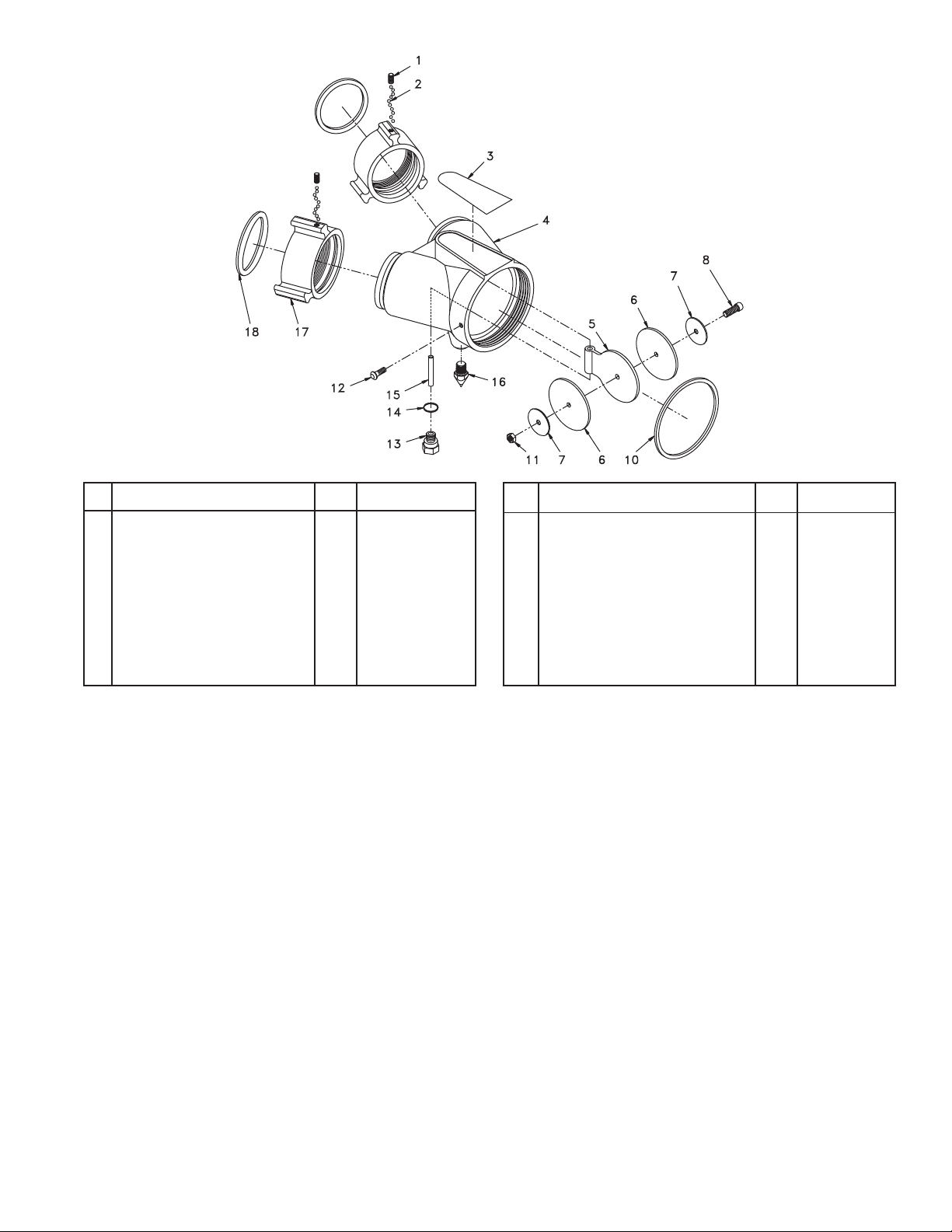
DOUBLE INLET OPTION
# DESCRIPTION QTY PART #
1/4-28 x 1/2 SOCKET SET 2 VT25-28SS500
1
3/16 SS BALL 96 V2120
2
SAFETY VALVE BASE LABEL OR 1 XL080 OR
3
NO VALVE BASE LABEL XL085
2.5" WYE 1 X712
4
2.5" CLAPPER 1 X772
5
2.5" CLAPPER GASKET 2 X762
6
WASHER 2 VW1.9X26-076
7
1/4-20 x 7/8 SHCS, SS 1 VT25-20SH875
8
# DESCRIPTION QTY PART #
O-RING-244 1 VO-244
10
1/4-20 STAINLESS NUT 1 VT25-20NT
11
1/4-28 X 3/4 BUTTON HEAD 1 VT25-28BH750
12
PIVOT BOLT 1 X784
13
O-RING-013 1 VO-013
14
CLAPPER PIVOT 1 X732
15
REAR SPIKE 1 X482
16
2.5" NH COUPLING (pictured) 2 M307N
17
2.5" COUPLING GASKET (pictured) 2 V3190
18
9.0 WARRANTY - CROSSFIRE SERIES
Task Force Tips, Inc., 2800 East Evans Avenue, Valparaiso, Indiana 46383 (“TFT”) warrants to the original purchaser of its Crossfire
Monitor and Stow-A-Way 800 Base (“equipment”), and to anyone to whom it is transferred, that the equipment shall be free from
defects in materialand workmanship during the five(5) year period from the date ofpurchase.
TFT’s obligation under this warranty is specifically limited to replacing or repairing the equipment (or its parts) which are shown by
TFT’s examination to be in a defective condition attributable to TFT. To qualify for this limited warranty, the claimant must return the
equipment to TFT, at 2800 East Evans Avenue, Valparaiso, Indiana 46383, within a reasonable time after discovery of the defect. TFT
will examine the equipment. If TFT determines that there is adefect attributable to it, it will correct theproblem within a reasonable time.
If the equipmentis covered by this limitedwarranty, TFT willassume the expensesof repair.
If any defect attributable to TFT under this limited warranty cannot be reasonably cured by repair or replacement, TFT may elect to
refund the purchase price of the equipment, less reasonable depreciation, in complete discharge of its obligations under this limited
warranty.If TFT makesthis election, claimant shall return the equipmentto TFT freeand clear of any liensand encumbrances.
This is a limited warranty. The original purchaser of the equipment, any person to whom it is transferred, and any person who is an
intended or unintended beneficiary of the equipment, shall not be entitled to recover from TFT any consequential or incidental
damages for injury to person and/or property resulting from any defective equipment manufactured or assembled by TFT. It is agreed
and understood that the price stated for the equipment is in part consideration for limiting TFT’s liability. Some states do not allow the
exclusion or limitationof incidental or consequential damages,so the above may not apply toyou.
TFT shall have no obligation under this limited warranty if the equipment is, or has been, misused or neglected (including failure to
provide reasonable maintenance) or if there have been accidents to the equipment or if it has been repaired or altered by someone
else.
THIS IS A LIMITED EXPRESS WARRANTY ONLY. TFT EXPRESSLY DISCLAIMS WITH RESPECT TO THE EQUIPMENT ALL IMPLIED
WARRANTIES OF MERCHANTABILITY AND ALL IMPLIED WARRANTIESOF FITNESS FORA PARTICULAR PURPOSE. THEREIS NO
WARRANTY OF ANY NATURE MADE BY TFT BEYONDTHATSTATED IN THEDOCUMENT.
This limited warrantygives you specific legal rights,and you may also have other rightswhich vary fromstate to state.
15
Page 16
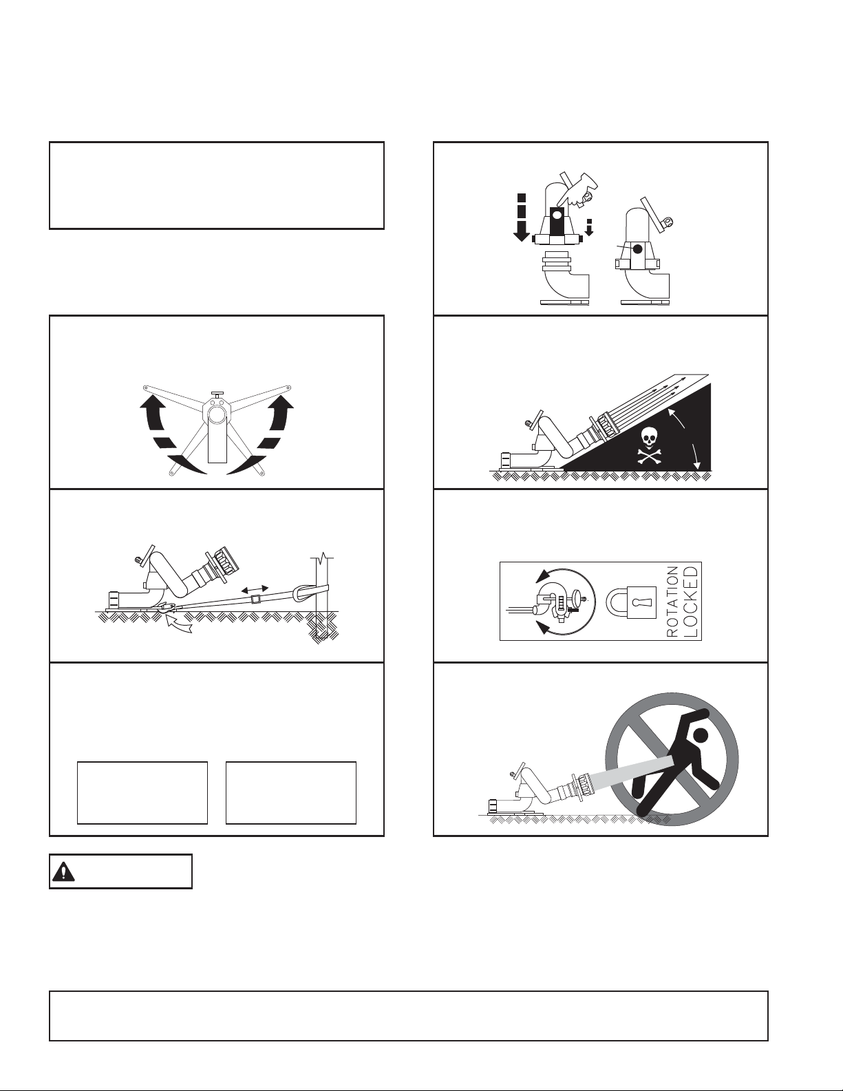
10.0 INSPECTION CHECKLIST
Monitor must be inspected forproper operation and function accordingto this checklist before eachuse. Before flowing water
check:
GENERAL
There is no obvious damage such as missing,
1
broken, or loose parts.
Hose(s) and nozzle are securely attached.
2
PORTABLE BASE
Legs are fully opened and locked in place.
3
All leg spikes are in contact with the ground.
4
Monitor is securely tied down with no slack
5
in anchor strap.
MONITOR TOP
Monitor top is securely attached.
7
A
B
C
Nozzle elevation is above safety stop.
8
Elevation handwheel adjusts elevation freely.
9
Monitor top freely swivels on base when
10
unlocked.
35°
Flow Limited to 800 gpm (3000 l/min)
6
Master nozzle pumped to 800 gpm
or
Stacked Tips Limited to:
1-3/8" dia 175 PSI
1-1/2" dia 140 PSI
1-3/4" dia 75 PSI
2" dia 40 PSI
Any monitor failing any part of the inspection checklist is unsafe and must have the problem
WARNING
corrected before use. Operating a monitor thatfails any of the above inspections isa misuse of this
equipment.
35 MM 12 BAR
38 MM 9.7 BAR
44 MM 5.2 BAR
50 MM 2.8 BAR
Rotation lock lever securely locks rotation.
11
Do Not point monitor in an unsafe direction.
12
TASK FORCE TIPS, Inc.
MADE IN USA •www.tft.com
©Copyright Task Force Tips, Inc. 1999-2011
3701 Innovation Way, Valparaiso, IN 46383-9327 USA
800-348-2686 • 219-462-6161 • Fax 219-464-7155
LIX-040 September 13, 2011 Rev05
 Loading...