

Task Force TFN10400 User Manual [en, es, fr]
24 Sp
Manual de Instrucciones
• Ensuring that tools which require
repair are not further used before
repair. Tags and physical segregation are recommended means of
control.
Danger indicates
an imminently
hazardous situation which, if not
avoided, WILL result in death or serious
injury.
Read and understand
tool labels and manual.
Failure to follow warnings, dangers, and cautions could result in
DEATH or SERIOUS
INJURY.
Do not use any type of reactive
gases, including, but not limited to,
oxygen and combustible gases, as a
power source. Use filtered, lubricat-
Description
This tool is designed for decorative
trim, molding, window casings, furniture trim, picture frame assembly, cabinetry, casebacks, and crafts. Features
include: convenient top loading magazine which holds up to 100 brads or staples, adjustable depth control,
adjustable exhaust, quick clear nose.
General Safety
Information
CALIFORNIA PROPOSITION 65
You
can create dust when you cut,
sand, drill or grind materials such as wood, paint,
metal, concrete, cement, or
other masonry. This dust often contains
chemicals known to cause cancer, birth
defects, or other reproductive harm.
Wear protective gear.
This product or its power cord contains
chemicals known to the State of
California to cause cancer and birth
defects or other reproductive harm.
Wash hands after handling.
This manual contains safety, operational and maintenance information.
OPERATOR’S RESPONSIBILITY:
The tool operator is responsible for:
• Reading and understanding tool
labels and manual.
• Selecting an appropriate tool actua-
tion system, taking into consideration the work application for which
the tool is used.
• The safe use of the tool.
• Ensuring that the tool is used only
when the operator and all other
personnel in the work area are
wearing ANSI Z87
eye protection
equipment, and
when required,
other appropriate
protection equipment such as head,
hearing and foot protection equipment. Serious eye or permanent
hearing loss could result.
• Assuring that the tool is kept in safe
working order as described in this
manual.
EMPLOYER’S RESPONSIBILITY:
• Selecting an appropriate tool actuation system, taking into consideration the work application for which
the tool is used.
• Ensuring that this manual is available to operators and personnel
performing maintenance.
• The safe use of the tool.
• Enforcing that the tool is used only
when the operator and all other
personnel in the work area are
wearing ANSI Z87
eye protection
equipment, and
when required,
other appropriate
protection equipment such as head,
hearing and foot protection equipment. Serious eye or permanent
hearing loss could result.
• Assuring that the tool is kept in safe
working order as described in this
manual.
• Assuring the proper maintenance of
all tools in employer’s possession.
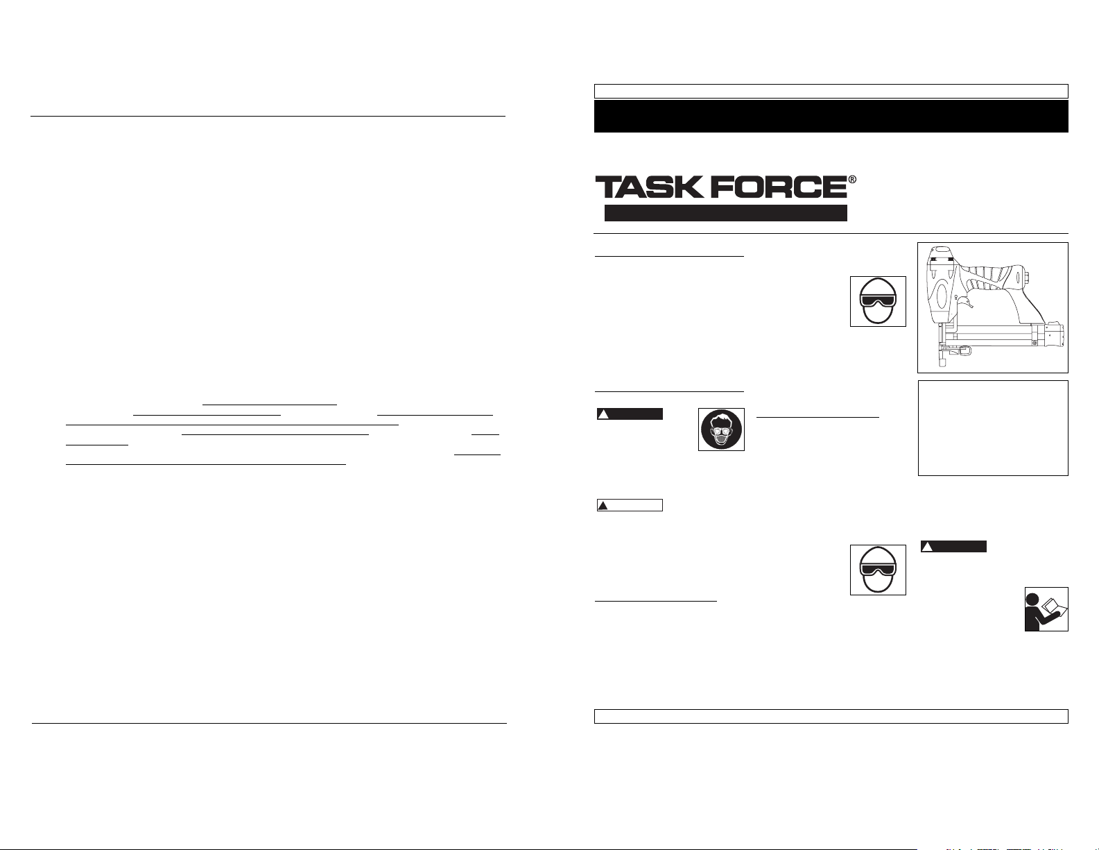
Operating Instructions Model TFN10400
2-in-1
Nailer/Stapler
Please read and save these instructions. Read carefully before attempting to assemble, install, operate or maintain the product described.
Protect yourself and others by observing all safety information. Failure to comply with instructions could result in personal injury, death and/or
property damage! Retain instructions for future reference.
IN710500AV 11/05
Task Force Nailers meet or exceed Industries’ Standards as set forth by the American National
Standard Institute/International Staple, Nail and Tool Association in ANSI/ISANTA SNT-101-2002.
© 2005
See Warranty on page 8 for important information about commercial use of this product.
Locate model and date code on tool
magazine and under nozzle shield,
and record below:
Model No. ________________________
Date Code ________________
Retain these numbers for
future reference.
Garantía Limitada
1. DURACIÓN: Desde la fecha de compra por parte del comprador original, según se detalla: 1 (un) año.
2. QUIEN OTORGA ESTA GARANTIA (EL GARANTE: Customer Service, 100 Production Drive, Harrison, Ohio 45030 Teléfono:
(800) 543-6400
3. QUIEN RECIBE ESTA GARANTIA (EL COMPRADOR): El comprador original (que no sea un revendedor) del producto.
4. PRODUCTOS CUBIERTOS POR ESTA GARANTIA: Cualquier clavadora, grapadora, herramienta neumática, pistola pulverizadora, inflador o accesorio neumático suministrado o fabricado por el Garante.
5. COBERTURA DE LA GARANTIA: Los defectos substanciales de material y fabricación que ocurran dentro del período de
validez de la garantía.
6. LO QUE NO ESTA CUBIERTO POR ESTA GARANTIA:
A. Las garantías implícitas, incluyendo aquellas de comercialidad E IDONEIDAD PARA FINES PARTICULARES, ESTAN
LIMITADOS A LO ESPECIFICADO EN EL PARRAFO DE DURACION. Si este producto es empleado para uso comercial,
industrial o para renta, la garantía será aplicable por noventa (90) días a partir de la fecha de compra. En algunos
estados no se permiten limitaciones a la duración de las garantías implícitas, por lo tanto, en tales casos esta limitación no es aplicable.
B. CUALQUIER PERDIDA DAÑO INCIDENTAL, INDIRECTO O CONSECUENTE QUE PUEDA RESULTAR DE UN DEFECTO,
FALLA O MALFUNCIONAMIENTO DEL PRODUCTO. En algunos estados no se permite la exclusión o limitación de
daños incidentales o consecuentes, por lo tanto, en tales casos esta limitación o exclusión no es aplicable
C. Cualquier falla que resulte de un accidente, abuso, negligencia o incumplimiento de las instrucciones de fun-
cionamiento y uso indicadas en el (los) manual(es) que se adjunta(n) al producto. Dichos accidentes, abusos por
parte del comprador, o falta de operar el producto siguiendo las instrucciones del manual de instrucciones suministrado también debe incluir la desconexión o modificación de los instrumentos de seguridad. Si dichos instrumen-
tos de seguridad son desconectados, la garantía quedaría cancelada.
D. Los ajustes normales explicados en el(los) manual(es) suministrado(s) con el producto.
E. Artículos o servicios normalmente requeridos para el mantenimiento del producto, tales como: anillos en O,
resortes, amortiguadores, defensas, hojas de impulsor, fusibles, baterías
, empaques, almohadillas o sellos, boquillas
de fluído, agujas, boquillas para rociar arena, lubricantes
, mangueras de material, elementos filtrantes, álabes de
motores, abrasivos, hojillas, discos para cortar, cinceles, retenes para cinceles, cortadores, collarines, mandriles,
mordazas para remachadoras, brocas para desarmadores, almohadillas para lijar
, soportes de almohadillas, mecanismo de impacto o cualquier otro artículo desgastable que no se haya enumerado específicamente . Estos artículos
sólo estarán cubiertos bajo esta garantía por noventa (90) días a partir de la fecha de compra original. Los artículos
subrayados sólo están garantizados por defectos de material o fabricación.
F. Defectos estéticos que no interfieran con la función del producto
7. RESPONSABILIDADES DEL GARANTE BAJO ESTA GARANTIA: Reparar o reemplazar, como lo decida el Garante, los productos o componentes que estén defectuosos, se hayan dañado o hayan dejado de funcionar adecuadamente, durante
el período de validez de la garantía
8. RESPONSABILIDADES DEL COMPRADOR BAJO ESTA GARANTIA:
A. Suministrar prueba fechada de compra y la historia de mantenimiento del producto.
B. Entregar o enviar el producto o componente al Centro de Servicio autorizado más cercano. Los gastos de flete, de
haberlos, deben ser pagados por el comprador.
C. Seguir las instrucciones sobre operación y mantenimiento del producto, tal como se indica(n) en el (los) manual(es)
del propietario
9. CUANDO EFECTUARA EL GARANTE LA REPARACION O REEMPLAZO CUBIERTO BAJO ESTA GARANTIA: La reparación o
reemplazo dependerá del flujo normal de trabajo del centro de servicio y de la disponibilidad de repuestos.
Esta garantía limitada es válida sólo en los EE.UU., Canadá y México y otorga derechos legales específicos. Usted también
puede tener otros derechos que varían de un Estado a otro. o de un país a otro.
REMINDER: Keep your dated proof of purchase for warranty purposes! Attach it to this manual or file it for safekeeping.
!
DANGER
!
WARNING
!
DANGER
Los anillos en O de la cubierta de la válvula
del gatillo están dañados
Los tornillos de la cubierta están flojos
Los anillos en O están dañados
La cubierta está dañada
Los tornillos están flojos
El empaque está dañado
La cubierta está desgastada
La boquilla está sucia
La suciedad o daños evitan el
desplazamiento libre de los sujetadores o
el mecanismo de impulso en el cargador
El resorte del mecanismo de impulso está
dañado
El flujo de aire hacia la herramienta es
inadecuado
El anillo en O del pistón está desgastado o le
falta lubricación
Los anillos en O de la válvula del gatillo
están dañados
Hay fugas de aire
Hay una fuga en el empaque de la tapa
La herramienta no está bien lubricada
El resorte de la tapa del cilindro está roto
El orificio de salida de la tapa está obstruído
La guía del mecanismo de impulso está
desgastada
Los sujetadores no son del tamaño adecuado.
Los sujetadores están doblados
Los tornillos del cargador o de la boquilla están
flojos
El mecanismo de impulso está dañado
Hay una fuga de aire en el
área de la válvula del gatillo
Hay una fuga de aire entre
la cubierta y la boquilla
Hay una fuga de aire entre
la cubierta y la tapa
La herramienta deja de
clavar un sujetador
La herramienta funciona
lentamente o pierde su
potencia
Hay sujetadores atascados
en la herramienta
Debe reemplazar los anillos en O y chequear el funcio-
namiento del elemento de funcionamiento al contacto
Debe apretar los tornillos
Debe reemplazar los anillos en O
Debe reemplazar la defensa
Debe apretar los tornillos
Debe reemplazar el empaque
Debe reemplazar la cubierta
Debe limpiar el canal del sistema de impulso
Debe limpiar el cargador
Debe reemplazar el resorte
Cheque las conexiones, la manguera o el compresor
Debe reemplazar los anillos en O. Lubríquelos.
Debe reemplazar los anillos en O
Debe apretar los tornillos y las conexiones
Debe reemplazar el empaque
Necesita lubricar la herramienta
Debe reemplazar el resorte
Debe reemplazar las partes internas dañadas
Debe reemplazar la guía
Debe usar los sujetadores recomendados para esta
herramienta
Reemplácelos con sujetadores en buenas condiciones
Debe apretar los tornillos
Debe reemplazar el mecanismo de impulso de sujetadores
23 Sp
Modelo TFN10400
Guía de Diagnóstico de Averías
Deje de usar la herramienta inmediatamente si alguno de los siguientes problemas ocurre.
Podría resultar en heridas graves. Cualquier reparación o reemplazo de piezas los debe hacer un
técnico calificado de servicio o un centro autorizado de servicio.
Problema Causa Solución
2
General Safety
Information (Continued)
ed, regulated compressed air only. Use
of a reactive gas
instead of compressed air may cause
the tool to explode
which will cause death or serious
personal injury.
Use only a pressure-
regulated compressed air source to
limit the air pressure
supplied to the tool.
The regulated pressure must not exceed 100 psi. If the
regulator fails, the pressure delivered to the tool must not exceed 200
psi. The tool could explode which
will cause death or serious personal
injury.
Never use gasoline or
other flammable liquids to clean the tool.
Never use the tool in
the presence of flammable liquids or gases. Vapors could
ignite by a spark and cause an explosion which will result in death or
serious personal injury.
Always remain in
a firmly balanced
position when
using or handling
the tool.
Do not remove, tamper with, or oth-
erwise cause the Work Contact
Element (WCE) or trigger to become
inoperable. Do not operate any tool
which has been
modified in a like
fashion. Death or
serious personal
injury could
result.
Do not touch the
trigger unless driving fasteners.
Never attach air
line to tool or
carry tool while
touching the trigger. The tool could eject a fastener
which will result in death or serious
personal injury.
Warning indicates
a potentially
hazardous situation which, if not
avoided, COULD result in death or
serious injury.
Always discon-
nect the tool
from the power
source when
unattended,
performing any
maintenance or repair, clearing a
jam, or moving the tool to a new
location. Always reconnect the air
line BEFORE loading any fasteners.
Do not load the tool with fasteners
when either the trigger is depressed
or the Work Contact Element (WCE)
is engaged. The tool could eject a
fastener causing death or serious
personal injury.
Always fit tool
with a fitting or
hose coupling
on or near the
tool in such a manner that all compressed air in the tool is discharged
at the time the fitting or hose coupling is disconnected. Do not use a
check valve or any other fitting which
allows air to remain in the tool.
Death or serious personal injury
could occur.
Never place hands or
any other body parts in
the fastener discharge
area of the tool. The
tool might eject a fastener and could result
in death or serious personal injury.
Never carry the
tool by the air
hose or pull the
hose to move the
tool or a compressor. Keep hoses
away from heat,
oil and sharp edges. Replace any
hose that is damaged, weak or
worn. Personal injury or tool damage could occur.
Always assume the tool contains
fasteners. Respect the tool as a
working implement; no horseplay.
Always keep others at a safe distance from the work area in case of
accidental discharge of fasteners.
Do not point the tool toward yourself or anyone whether it contains
fasteners or not. Accidental triggering of the tool could result in death
or serious personal injury.
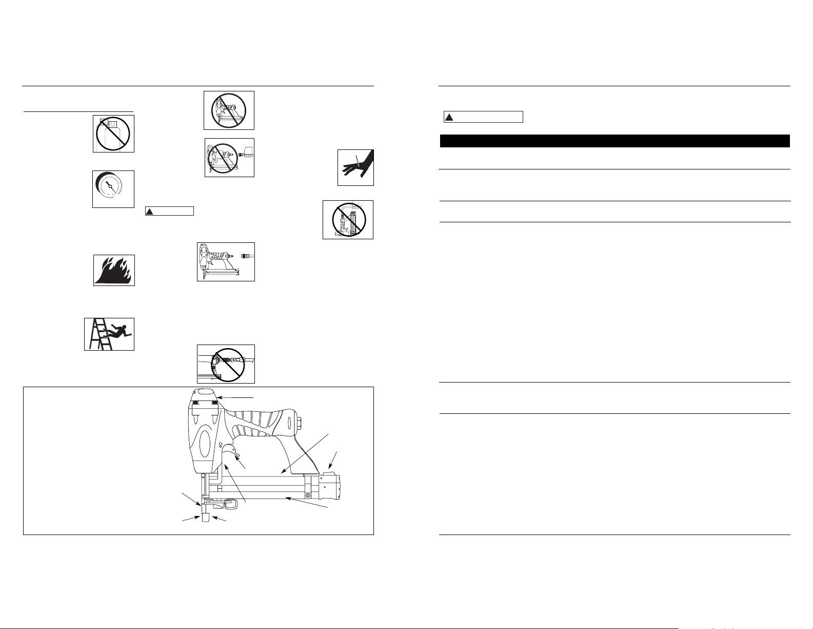
Operating Instructions
• REQUIRES: 0.8 SCFM with 10 fasteners per minute @ 90 psi
• AIR INLET: 1/4” NPT
• FASTENER SIZE RANGE: 3/8” to
1 1/4”
• MAGAZINE CAPACITY:
100 fasteners per load, 18 gauge
• STAPLES: 1/4” crown
• WEIGHT: 2 lbs., 15 oz.
• LENGTH: 10 1/2”
• HEIGHT: 9 1/2”
• MAXIMUM PRESSURE: 100 psi
• PRESSURE RANGE: 60 - 100 psi
Tool Components And Specifications
Cap exhaust
100 psi
MAX.
Warning label
Latch button
Magazine
Fastener discharge area
Work contact element (WCE)
Trigger
Quick clear nose
Adjustable depth control
(not visible)
O
CO
2
!
WARNING
!
ADVERTENCIA
1
1
MPA
bar
psi
1
1
7
.
.
.
.
5
9
1
6
8
1
1
3
4
1
22 Sp
Manual de Instrucciones
3
General Safety
Information (Continued)
Do not drive a fas-
tener on top of
other fasteners.
The fastener could
glance and cause
death or a serious
puncture wound.
Do not operate
or allow anyone
else to operate
the tool if any
warnings or
warning labels
are not legible.
Warnings or warning labels are located on the tool magazine and body.
Do not drop or throw the tool.
Dropping or throwing the tool can
result in damage that will make the
tool unusable or unsafe. If the tool
has been dropped or thrown, examine the tool closely for bent, cracked
or broken parts and air leaks. STOP
and repair before using or serious
injury could occur.
Caution indicates
a potentially hazardous situation which, if not avoided,
MAY result in minor or moderate
injury.
Do not make any modifications to the
tool without first obtaining written
approval. Do not use the tool if any
shields or guards are removed or
altered. Do not use the tool as a hammer. Personal injury or tool
damage may occur.
Avoid long extended periods of
work with the tool. Stop using the
tool if you feel pain in hands or
arms.
Always check that the Work Contact
Element (WCE) is operating properly. A fastener could accidentally be
driven if the WCE is not working
minimum of 60 psi when the tool is
being used. An inadequate air supply can cause a loss of power and
inconsistent driving.
2. Use 3/8” air
hoses with a
minimum
working pressure of 150
psi. Use 1/2” air hoses for 50’ run or
longer. For better performance,
install a 3/8” quick plug (1/4” NPT
threads) with an inside diameter of
.315" (8mm) on the tool and a 3/8”
quick coupler on the air hose.
3. Use a pressure
regulator on the
compressor, with
an operating
pressure of 0 -125
psi. A pressure regulator is required
to control the operating pressure of
the tool between 60 and 100 psi.
SINGLE SEQUENTIAL MODE
This mode requires the trigger to be
pulled each time
a fastener is driven. The tool can
be actuated by
depressing the
WCE against the work surface followed
by pulling the trigger.
The trigger must be released to reset
the tool before another fastener can be
driven.
CHECKING THE WORK CONTACT
ELEMENT (WCE)
Check the opera-
tion of the Work
Contact Element (WCE) trip mechanism
before each use. The WCE must move
freely without binding through its
properly.
Personal injury
may occur (See
"Checking the
Work Contact
Element"
Section).
Disconnect air
supply and release tension from the
pusher before attempting to clear
jams because fasteners can be ejected from the front of the tool.
Personal injury may occur.
Notice indicates
important infor-
mation, that if not followed, MAY
cause damage to equipment.
Avoid using the tool when the mag-
azine is empty. Accelerated wear on
the tool may occur.
Clean and check all air supply hoses
and fittings before connecting the
tool to an air supply. Replace any
damaged or worn hoses or fittings.
Tool performance or durability may
be reduced.
Air compressors providing air to the
tool should follow the requirements
established by the American
National Standards Institute
Standard B19.3-1991; Safety
Standard for Compressors for
Process Industries. Contact your air
compressor manufacturer for
information.
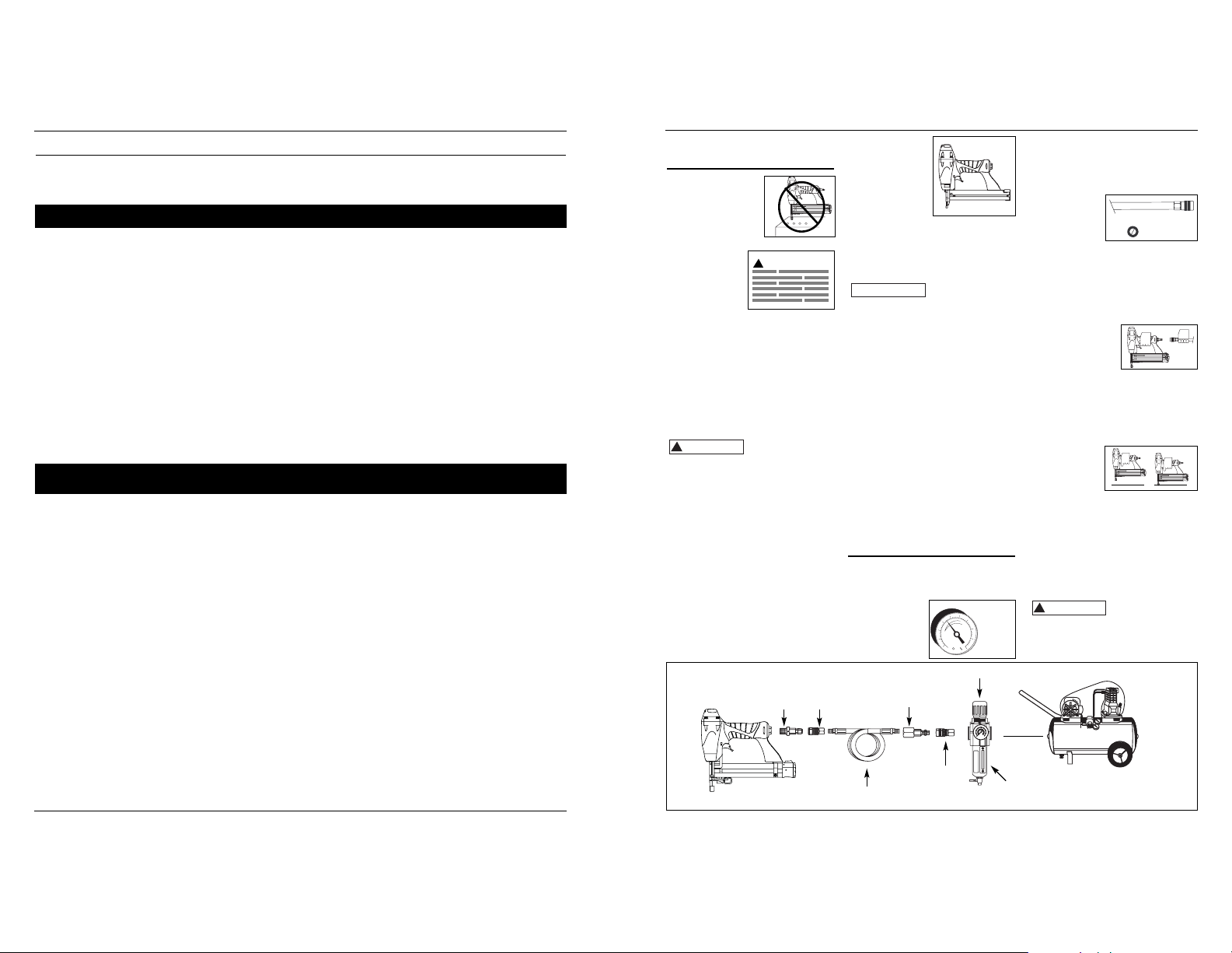
Operating The Tool
RECOMMENDED HOOKUP
The illustration below shows the
recommended hookup for the tool.
1. The air compressor must
be able to
maintain a
Recommended Hookup
Quick
Plug
Quick
Coupler
Air
Hose
Quick Plug
(Optional)
Quick
Coupler
(Optional)
Regulator
Filter
Calibre Clavos por Clavos por
Modelo # Longitud
del cuerpo
Acabado Cabeza Unión
línea Caja
aFB001600 15,9mm (5/8”) Calibre 18 Galvanizado De puntilla/Café Adhesivo 100 5000
FB002000 19,1mm (3/4”) Calibre 18 Galvanizado De puntilla/Café Adhesivo 100 5000
FB002500 25,4mm (1”) Calibre 18 Galvanizado De puntilla/Café Adhesivo 100 5000
FB003000 31,8mm (1
1
⁄
4”) Calibre 18 Galvanizado De puntilla/Café Adhesivo 100 5000
FB180016 15,9mm (5/8”) Calibre 18 Galvanizado De puntilla/Café Adhesivo 100 1000
FB180025 25,4mm (1”) Calibre 18 Galvanizado De puntilla/Café Adhesivo 100 1000
FB180030 31,8mm (1
1
⁄
4”) Calibre 18 Galvanizado De puntilla/Café Adhesivo 100 1000
Clavos
Estos clavos para acabado de los puede comprar en su tienda más cercana. Si necesita ayuda para encontrar un artículo,
comuníquese al 1-800-543-6400. Los clavos cumplen o exceden el estándar ASTM F1667
Información de intercambio
TFN10400AV can use 3/8” to 1-1/4” 18 gauge brad nails designed for the following tools:
• Bostitch
®
BT125SK-2 • Campbell Hausfeld® NB0030
• DeWalt
®
D51238K • Hitachi® NT32AE
• Paslode
®
T125-F18 • Porter Cable®BN125
• Senco
®
Finish Pro™ 15
Grapas
Estas grapas para acabado de los puede comprar en su tienda más cercana. Si necesita ayuda para encontrar un artículo,
comuníquese al 1-800-543-6400. Las grapas cumplen o exceden las especificaciones Federales FF-N-105B.
Información de intercambio
TFN10400AV can use 3/8” to 1-1/4” 18 gauge, 1/4” crown staples designed for the following tools:
• Campbell Hausfeld
®
SN258K • Hitachi® N3804AB
• Porter Cable
®
NS100, NS150 • Senco®SLS15, SLS18, SLS25XP
Calibre Fusión de Grapas Grapas
Modelo # Longitud de la grapa Corona Punta Acabado la linea por linea por caja
FN158K00 12,7mm (1/2”) Calibre 18 6,4mm(1/4") Cincel Galvanizado/Cubierta por vinilo Adhesivo 100 5000
FN168K00 15,9mm (5/8”) Calibre 18 6,4mm(1/4") Cincel Galvanizado/Cubierta por vinilo Adhesivo 100 5000
FN180615 12,7mm (1/2”) Calibre 18 6,4mm(1/4") Cincel Galvanizado/Cubierta por vinilo Adhesivo 100 1000
FN180620 19,1mm (3/4”) Calibre 18 6,4mm(1/4") Cincel Galvanizado/Cubierta por vinilo Adhesivo 100 1000
FN180625 25,4mm (1”) Calibre 18 6,4mm(1/4") Cincel Galvanizado/Cubierta por vinilo Adhesivo 100 1000
FN180630 31,8mm (1
1
⁄
4”) Calibre 18 6,4mm(1/4") Cincel Galvanizado/Cubierta por vinilo Adhesivo 100 1000
FN208K00 19,1mm (3/4”) Calibre 18 6,4mm(1/4") Cincel Galvanizado/Cubierta por vinilo Adhesivo 100 5000
FN258K00 25,4mm (1/4”) Calibre 18 6,4mm(1/4") Cincel Galvanizado/Cubierta por vinilo Adhesivo 100 5000
Sujetadores
60 psi
Min.
100 psi
Max.
150 PSI WP
3/8” I.D.
Model TFN10400
!
CAUTION
!
WARNING
NOTICE
!
CAUTION
Si no se
retiran
todos los sujetadores éstos saldrán por el
frente de la herramienta.
3. Destrabe el gan-
cho presionando
el botón en el
lado del cargador. El botón
destrabará el gancho de la boquilla.
4. Ahora se puede
girar la puerta,
dejando al
descubierto el
sujetador que
esté trabado.
5. Retire todos
los sujetadores que
estén trabados, utilizando unas pinzas o un destornillador
si fuera necesario.
6 Vuelva a girar la
puerta a su posición de cerrado.
7. Vuelva a presion-
ar el botón para
levantar el gancho. Cierre la
puerta y suelte el
botón para volver a trabar el gancho con la boquilla.
8. Asegúrese de que el
gatillo y el elemento
de contacto de trabajo (WCE) se muevan libremente
hacia arriba y hacia abajo sin
adherirse ni trabarse.
!
entire travel distance. The WCE spring
must return the WCE to its fully extended position after being depressed. Do
not operate the tool if the WCE trip
mechanism is not operating properly.
Personal injury may occur.
1. Disconnect the
air supply from
the tool.
2. Remove all fasteners from the
magazine (see
Loading/
Unloading).
3. Make sure the trigger and work contact element (WCE)
move freely up and
down without sticking or binding.
4. Reconnect air
supply to the
tool.
5. Depress the Work
Contact Element
(WCE) against the
work surface without pulling the trigger. The tool MUST NOT OPERATE.
Do not use the tool if it operates
without pulling the trigger.
Personal injury may result.
6. Remove the tool
from the work surface. The Work
Contact Element
(WCE) must return
to its original down
position. The tool MUST NOT
OPERATE. Do not use the tool if it
operates while lifted from the work
surface. Personal injury may result.
7. Pull the trigger and
depress the
work contact
element
(WCE) against the work surface. The
3. Para clavar el sujetador más profundo, gire la rueda (C) hacia la izquierda hasta el punto deseado.
4. Asegúrese que el
gatillo y el Elemento
de Contacto de
Trabajo se mueven
libremente hacia
arriba y hacia abajo sin atascarse o
pegarse después de cada ajuste.
PARA AJUSTAR LA DIRECCION DEL
TUBO DE ESCAPE
El modelo
TFN10400 está
equipado con un
deflector
ajustable de la
dirección del tubo
de escape. Éste le permite al usuario
cambiar la dirección del tubo de
escape. Simplemente mueva el deflector hacia la dirección deseada.
QUÉ HACER CUANDO LA HERRAMIENTA TENGA UN SUJETADOR
ATASCADO
1. Desconecte la
herramienta de
la fuente de
suministro de
aire.
2. Remueva todos
los sujetadores
del depósito
(vea Carga /
Descarga).
Servicio Técnico
Si desea hacer alguna pregunta referente a la reparación u operación de las
herramientas, o para solicitar copias
adicionales de este manual, sírvase llamar a nuestro número especial, 1-800543-6400.
Sujetadores y Piezas de
Repuesto
El desempeño de las herramientas, la
seguridad y la duración pueden
disminuir si no se utilizan los
sujetadores adecuados. Cuando ordene
piezas de repuesto o sujetadores,
especifique el número de la pieza.
Para reparar la herramienta
La herramienta debe ser reparada únicamente por personal calificado, y
deben usar piezas de repuesto y accesorios originales, o piezas y accesorios
que funcionen de manera equivalente.
Para colocarle los sellos
Cada vez que repare una herramienta
deberá limpiarle y lubricarle las partes
internas. Le recomendamos que use
Parker O-lube o un lubricante equivalente en todos los anillos en O. A cada
anillo en O se le debe dar un baño de
lubricante para anillos antes de instalarlos. Igualmente, deberá ponerle un
poco de aceite a todas las piezas que se
mueven y muñones. Finalmente,
después de haberla ensamblado y antes
de probar la herramienta deberá
ponerle unas cuantas gotas de aceite
sin detergente 30W u otro aceite similar, en las líneas de aire.
Modelo TFN10400
21 Sp
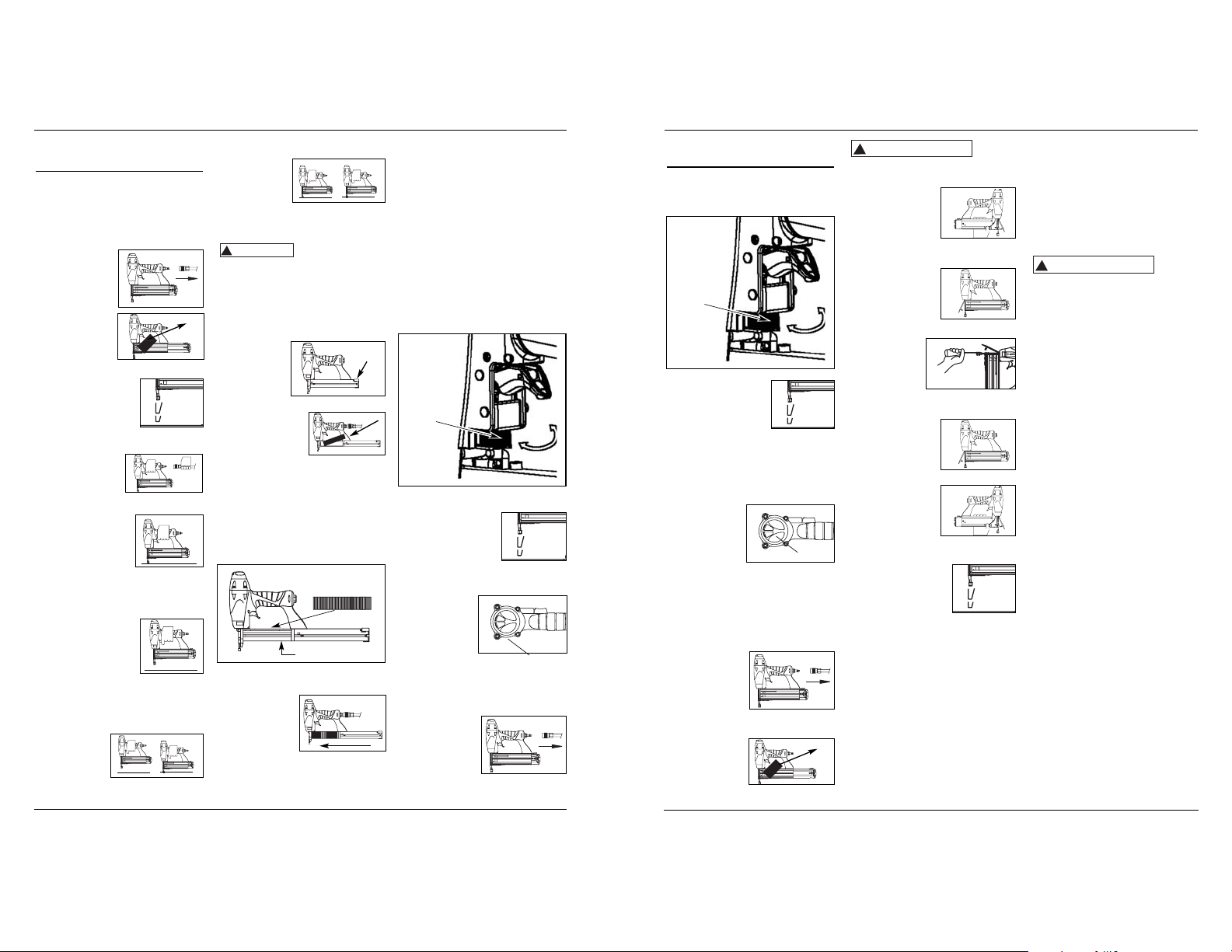
ADJUSTING THE FASTENER PENETRATION
The tool is equipped with an adjustable
depth of drive feature. This allows the
user to determine how deep a fastener
will be driven into the work surface.
1. Adjust operating pressure so fasteners are driven consistently. Do not
exceed 100 psi.
2. For shallow penetration, turn the
wheel (C) to right to the extent
desired.
3. For deeper penetration, turn the
wheel (C) to left to the extent
desired.
4. Make sure trigger and work contact
element (WCE)
move freely up and
down without binding or sticking after
each adjustment.
ADJUSTING THE DIRECTION OF THE
EXHAUST
The TFN10400 is
equipped with an
adjustable direction exhaust
deflector. This is
intended to allow
the user to change the direction of the
exhaust. Simply twist the deflector to
any direction desired.
CLEARING A JAM FROM THE TOOL
1. Disconnect the
air supply from
the tool.
tool MUST NOT OPERATE.
8. Depress the
Work Contact
Element
(WCE) against
the work surface. Pull the trigger. The tool
MUST OPERATE.
An improperly
functioning tool
must not be used. Do not actuate the
tool unless the tool is placed firmly
against the work piece.
LOADING/UNLOADING THE TOOL
1. Always connect the tool to the air
supply before loading fasteners.
2. Push down
on the latch
button. Pull
back on the
magazine
cover.
3a. For nails, insert a
stick of nails (see
"Fasteners" section) into the
magazine. Make
sure the pointed ends of the fasteners are resting on the bottom ledge
of the magazine when loading.
Make sure the nails are not dirty or
damaged.
3b. For staples, load a clip of staples
with the crowns straddling the
magazine rail.
4. Push the magazine cover forward
until latch button pops up.
5. Always unload
all fasteners
before removing tool from
service.
Unloading is the reverse of loading,
except that you must disconnect
the air supply before unloading.
Operating Instructions
4
movement
1
2
1
2
Latch
Button
Magazine rail
Gire
(C)
movemiento
Operating The Tool
(Continued)
(C)
Cómo usar la
Herramienta (Cont.)
movimiento
movement
Rotate
ADVERTENCIA
!
WARNING
!
ADVERTENCIA
BUILT TO LAST
 Loading...