


ITEM #241482
YARD CHIPPER
MODEL # 26093
RE
AD YOUR OPERATOR’S MANUAL COMPLETELY AND CAREFULLY BEFORE
ATTEMPTING
EQUIPMENT SHOULD READ AND UNDERSTAND ALL SAFETY RULES PRINTED ON THE MACHINE
AND IN THIS OPERATOR’S MANUAL BEFORE USE.
NOTICE: On the nameplate of your machine you will find the serial number and MFG date code of your unit.
Please record these numbers on this manual cover for future service reference.
MFG. DATE ________ PURCHASE DATE: _________
TO SET UP OR OPERATE YOUR NEW POWER TOOL. ALL OPERATORS OF THIS
Questions, problems, missing parts? Before returning to your retailer, call our customer
service department at 1-800-444-6742, 8:00 a.m.-6:00 p.m., EST, Monday-Thursday,
8:00 a.m.-5:00 p.m.,
CAUTION - FOR YOUR SAFETY
EST, Friday.
PRINTED IN CHINA

2
Product specification............................................................................................2
General safety rules.............................................................................................3
Specific safety rules for yard chippers.................................................................5
Electrical information............................................................................................6
Know your chipper...............................................................................................8
Assembly and Adjustments..................................................................................9
Operation............................................................................................................12
Maintenance.......................................................................................................14
Warranty.............................................................................................................16
Parts lists............................................................................................................17
YARD CHIPPER
ITEM NUMBER:...........................................................................................241482
MODEL NUMBER:.........................................................................................26093
MOTOR..................................................................................120V AC, 60 Hz, 15A
SPEED....................................................................................................4,000RPM
CHIPPER CAPACITY...................................................................1-3/8 in. (35 mm)
DIAMETER.....................................................................................1-3/8 in.(35 mm)
HEIGHT....................................................................................37-1/2 in. ( 950 mm)
WEIGHT................................................................................... 31 lb 6 oz (14.35 kg)
TABLE OF CONTENTS
PRODUCT SPECIFICATIONS
Assembling this YARD Chipper need as follows tools:
(1) L-wrench
(2) 13mm wrench
(3) screwdriver

Safety is a combination of common sense, staying alert, and knowing how to
use your yard chipper properly.
1. READ and become familiar with this entire instruction manual. LEARN the
tool’s applications, limitations, and possible hazards.
2. AVOID DANGEROUS CONDITIONS. DO NOT use power tools in wet or
damp areas or expose them to rain.
3. DO NOT use power tools in the presence of flammable liquids or gases.
4. KEEP BYSTANDERSAT A SAFE DISTANCE FROM the work area when
the tool is operating. NEVER allow children near the tool.
5. DO NOT FORCE THE TOOL to do a job for which it was not designed.
6. DRESS FOR SAFETY. DO NOT wear loose clothing, gloves, neckties, or
jewelry (rings, watches, etc.) when operating tool. Loose clothing can get
caught and pull you into moving parts.
7. ALWAYS WEAR EYE PROTECTION.
8. ALWAYS remove the power cord plug from the electric outlet when making
adjustments, changing parts, cleaning or working on the tool.
9. AVOIDACCIDENTAL START-UPS. Make sure the power switch is in the
OFF position before plugging in the power cord.
10. DO NOT abuse the power cord. Do not use it to carry the tool. Keep cord
away from heat, oil, sharp edges, or moving parts. Replace damaged cords
immediately; they may create a shock or fire hazard.
11. NEVER LEAVE A RUNNING TOOL UNATTENDED. Turn the power switch
to OFF. Do not leave the tool until it has come to a complete stop.
12. Keep proper footing and balance at all times. Wear oil-resistant,
rubber-soled footwear.
TO AVOID MISTAKES THAT COULD CAUSE SERIOUS
INJURY, DO NOT PLUG IN THE CHIPPER UNTILTHE FOLLOWING
STEPS HAVE BEEN READ THOROUGHLY.
3
GENERAL SAFETY RULES
WARNING

13. ALWAYS keep tool clean and in good working order.
14. Check for proper alignment of moving parts, binding, breakage, or any other
conditions that may affect the tool’s operation. Any part that is damaged
15. DO NOT operate tool if you are under the influence of any drugs, alcohol
or medication that could affect your ability to use the tool properly.
16. Do not use solvents, brake fluids, gasoline, or other petroleum products to
clean the tool, they may damage plastic parts.
4
should be properly repaired or replaced before use.
GENERAL SAFETY RULES-CONTINUE
ALWAYS WEAR EYE PROTECTION.
A yard chipper can throw foreign objects into your eyes which could
cause permanent eye damage.
ALWAYS wear safety goggles (not glasses). Ordinary eyeglasses
have only impact-resistant lenses—they are
NOT safety goggles.

1. Be thoroughly familiar with the operation of the chipper before initial use.
2. NEVER put your hands into the hopper. Always use the push stick supplied
with your chipper to push items into the hopper.
3. DO NOT try to force objects that exceed the recommended diameter and
capacity of the chipper: 1-3/8 in. (35cm).
4. AVOID ACCIDENTAL START-UPS. Be sure switch is OFF when
plugging in.
5. DO NOT FORCE THE CHIPPER. It will do the job better and with less
likelihood of injury at the rate for which it was designed.
6. Before putting objects into the hopper, remove any stones, debris, or
objects that could damage the blades.
7. During operation, ensure that there are no other persons or animals within
a radius of 10 feet. Stop using the machine while people, especially
children, or pets, are nearby.
8. NEVER reach under the chipper until it has completely stopped. The
blade may continue to rotate for a time after being switched OFF.
9. MAKE all adjustments with the power OFF and the chipper disconnected
from the power source.
10. ALWAYS use accessories provided or recommended by the manufacturer.
Do not use substitutes.
11. KEEP guards in place and in working order. Keep blades sharp. Keep
hands and feet away from cutting areas.
5
NEVER REACH INTO THE HOPPER UNTIL THE
CHIPPER HAS COME TO A COMPLETE STOP AND IS
UNPLUGGED.
THE CHIPPER WILL CONTINUE TO ROTATE FOR A FEW
SECONDS
AFTER IT IS SWITCHED OFF.
NEVER PLACE HANDS INTO THE EJECTION CHUTE—A
SERIOUS INJURY WILL OCCUR.
SPECIFIC SAFETY RULES FOR YARD CHIPPERS
WARNING
WARNING

This yard chipper has a plug that looks like the one shown in Fig. A.
The yard chipperis double insulated to providea dual thickness of insulation
between you and the tool’s electrical system. All exposed metal parts are
insulated.
IN ALL CASES, MAKE CERTAIN THE RECEPTACLE IN
QUESTION IS PROPERLY GROUNDED. IF YOU ARE NOT SURE,
HAVE A CERTIFIED ELECTRICIAN CHECK THE RECEPTACLE.
6
Fig. A
1) 2-prong plug
2) Properly grounded extension cord
ELECTRICAL INFORMATION
CAUTION
WARNING: TO AVOID ELECTRIC SHOCK HAZARDS, FIRE HAZARDS,
OR DAMAGE TO THE TOOL, USE PROPER CIRCUIT PROTECTION.
YOUR CHIPPER IS WIRED AT THE FACTORY FOR 12OV OPERATION.
CONNECT TO 120 V, 15 A CIRCUIT AND USE A 15 A CIRCUIT BREAKER.
TO AVOID SHOCK OR FIRE WHEN THE POWER CORD IS WORN, CUT,
OR DAMAGED IN ANYWAY, REPLACE IT IMMEDIATELY.
DOUBLE INSULATED
WARNING:TO AVOID INJURY,WHEN SERVICING THE CHIPPER
USE ONLY IDENTICAL REPLACEMENT PARTS.1-800-444-6742
WARNING:DOUBLE INSULATION DOES NOT TAKE THE PLACE OF
NORMAL SAFETY PRECAUTION WHEN OPERATING THIS TOOL.
WARNING:TO AVOID ELECTRIC SHOCK:
1. Use only identical replacement parts when serving a tool with double
insulation. Servicing should be performed by a qualified technician.
2. Do not use in wet or damp or expose to rain.

GUIDELINES FOR USING EXTENSION CORDS
Make sure your extension cord is in good condition. When using an extension
cord, be sure to use one of heavy enough gauge to carry the current your product
will draw. An undersized cord will cause a drop in line voltage resulting in loss of
power and overheating. The table below shows the correct size to be used
according to cord length and nameplate ampere rating. If in doubt, use the next
heavier gauge. The smaller the gauge number, the heavier the cord.
Minimum
Gauge for Extension Cords(AWG)
(when using 120 V only)
Be sure your extension cord is properly wired and in good condition. Always replace
a damaged extension cord or have it repaired by a qualified person before using it.
Keep your extension cords away from sharp objects, excessive heat and damp or
wet areas.
Use a separate electrical circuit for your tools. This circuit must not be less than
12 gauge cord and should be protected with a 15 amp time delayed fuse.
Before connecting the motor to the power line, make sure the switch is in the OFF
position and the electric current is rated the same as the current stamped on the
motor nameplate. Running at a lower voltage will damage the motor.
THIS TOOL MUST BE GROUNDED WHILE IN USE TO
PROTECT THE OPERATOR FROM ELECTRICAL SHOCK.
Amp Rating Total Lengthof Cord in Feet (meters)
More Than Not More Than 25 (7.6) 50 (15.2) 100 (30.4) 150(45.7)
0 6 18 16 16 14
6 10 18 16 14 12
10 12 16 16 14 12
12 16 14 12 Not Recommended
THIS LAWN TOOL IS FOR OUTDOOR USE ONLY. DO
NOT EXPOSE TO RAIN OR USE IN DAMP LOCATIONS.
7
ELECTRICAL INFORMATION
WARNING
WARNING
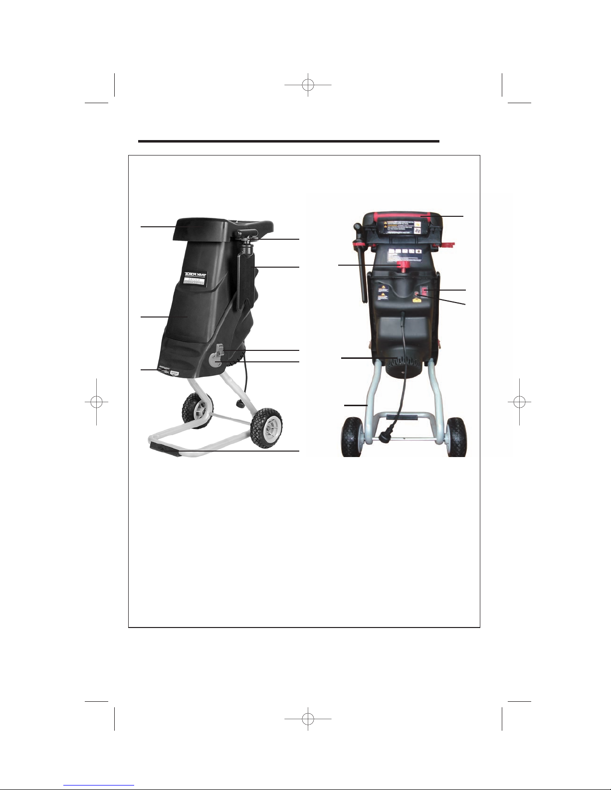
8
1. Hopper
2. Handle
3. Housing
4. Motor Housing
5. Release Knob
6. Power Switch
7. Discharge Chute
8. Stand with Wheels
9. Circuit Breaker
10. Clip Holder
11. Bag Clip
2
5
6
4
8
7
3
9
10
11
KNOW YOUR YARD CHIPPER
12
14
12. Push Bar Holder
14. Push Bar
13. Underlay
13
1
1
2
3
4
5
8
9
13
6
10
11
12
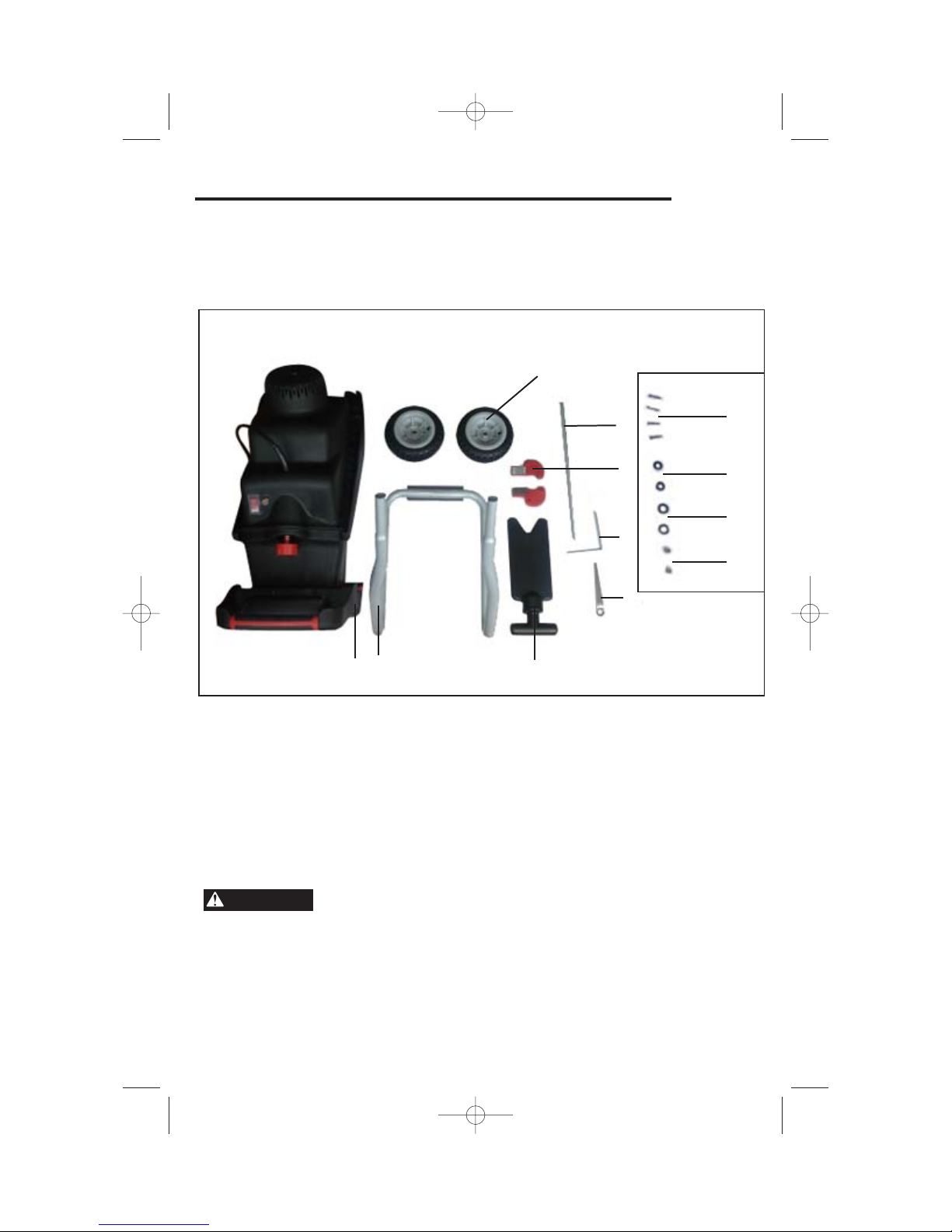
UNPACKING (Fig. B)
Remove the chipper components from the packaging and examine them carefully.
.
NOTE: Do not discard box or any packing material until all parts are examined.
9
1
Housing with hopper 1 pcs
2 Push Bar 1 pcs
3 Wheel 2 pcs
4 Axle 1 pcs
5 Clip Holder 2 pcs
6 Screw 4 pcs
7 Collecting Bag (not show) 1 pcs
8 L-wrench 1 pcs
9 13mm wrench 1 pcs
10 Wheel Nut 2 pcs
11 Inner Washer 2 pcs
12 Outer Washer 2 pcs
13 Stand Assembly 1 pcs
IF ANY PART OF THE CHIPPER IS MISSING OR
DAMAGED, DO NOT PLUG
THE TOOL IN
UNTIL THE DAMAGED PART IS
REPAIRED OR REPLACED..
Fig. B
WARNING
ASSEMBLY AND ADJUSTMENTS

ASSEMBLY INSTRUCTIONS
The chipper must be fully assembled before use.
Fig.3
BEFORE MAKING ANY ADJUSTMENTS.
10
TO AVOID INJURY, ALWAYS TURN THE SWITCH OFF
AND DISCONNECT THE CHIPPER FROM THE POWER OUTLET
BEFORE MAKING ANY ADJUSTMENTS.
Fig.1
Fig.2
Fig.3
1
2
3
5
4
6
7
8
1. Place one end of the axle (2) into the
hole on the leg (1) as shown in Fig.1
Spread legs slightly to allow the other
end of the axle into the opposite hole.
2. Place large washer (3) onto axle.
3. Place wheel (4) onto axle followed by
the small washer (5) and wheel nut (6)
as Fig.2.
4. Repeat steps 2 and 3 for the opposite
side.
5. Place the “L” wrench (7) through the
hole in the axle and then using the
14mm wrench (8), tighten each wheel
nut in turn, while holding the axle
steady with the “L” wrench.
WARNING
ASSEMBLY AND ADJUSTSMENTS

11
Attach legs to chipper (Figs.5 and 6)
The legs are attached to the bottom of the chipper. The top pa rt of the chipper
is held closed by a lock knob.
1. Turn the chipper housing upside down.
(Step 1,Fig.4)
2. Place the leg assembly into the holes
on the housing. (Step 2,Fig.5)
3. Push firmly into place.
4. Position a clip holder (Step 3,Fig.6) on
the side of the housing and screw
(Step 4,Fig.6) into place. Repeat for the
opposite side.
5. Make sure the chipper is properly
assembled, and then turn the right way
up.
Fig.4
Step 1
Fig.5
Step 2
Fig.6
Step 4
Step 3
ASSEMBLY AND ADJUSTMENTS
OPERATING INSTRUCTIONS
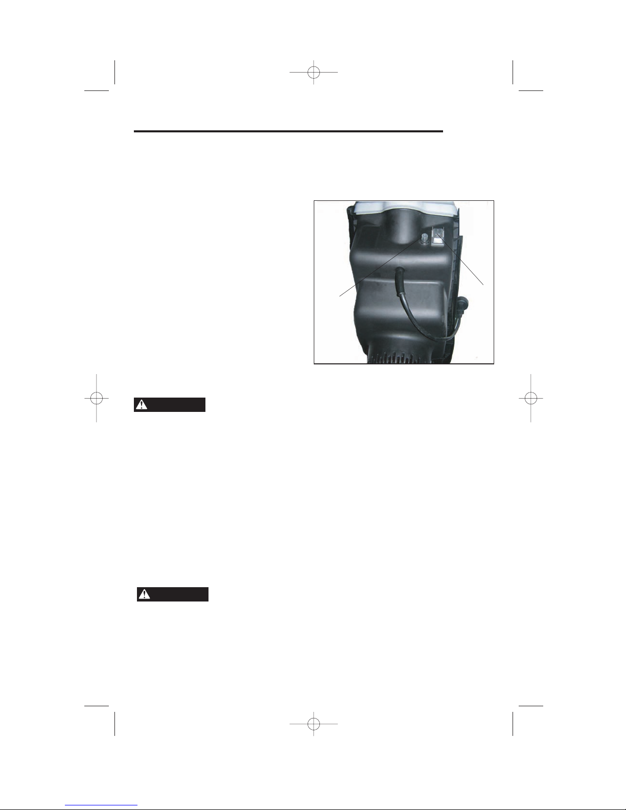
ON/OFF Switch (Fig. 7)
The ON/OFF switch (1). A circuit breaker (2) is located below the switch.
To operate the shredder:
1. Plug the shredder into a properly
grounded 3-prong outlet.
2. Flip the switch (1)
to the ON
position. If the shredder does not
start, flip the switch to the OFF
position and press the reset
button
(2)
, then flip the switch to the
ON position.
3. Flip the switch (1) to the OFF
position to turn offthe shredder.
Allow at least 5 seconds for the
blade to stop rotating.
Overload protection (Fig. 7)
This yard chipper has a reset overload
feature. The reset button
will restart the
motor after it shuts off due to overloading or low voltage. If the motor stops
during operation:
1.Turn the ON/OFF (1) switch to the OFF position.
2.Wait about five minutes for the motor to cool.
3.Push in on the reset button (2) .
4.Turn the switch (1) to the ON position.
12
ALWAYS ALLOW 5 SECONDS OR MORE FOR THE
BLADE
TO STOPROTATING AFTER TURNING OFF THE CHIPPER.
TO PREVENT AN ACCIDENTAL START-UP IF THE RESET
BUTTON IS PUSHED,
THE ON/OFF SWITCH SHOULD BE IN THE OFF
POSITION AND THE PLUG SHOULD BE REMOVED FROM THE POWER
SOURCE WHILE COOLDOWN TAKES PLACE.
Fig. 7
1
2
OPERATION
WARNING
WARNING
Chipping yard waste (Fig. 8)
The chipper is designed to work on leaves, other yard waste and debris, and
sticks and twigs up to 1-3/8 in. (35mm) in diameter. The chipper material will
accumulate directly on the ground under the chipper .
CAUTION: Do not attempt to chip material that exceeds the capacity of t he
chipper.
1. Turn ON the chipper.
2. Place sticks in the narrow opening of
the hopper. Do not place your hands
inside the hopper.
3. Do not feed sticks that are greater than
1-3/8 in.(35mm) in diameter.
4. Turn the chipper OFF and allow it
to come to a complete stop.
13
DO NOT TRY TO CHIP ANY MATERIAL THAT EXCEEDS
THE CAPACITY OF THIS TOOL. DOING SOMAYCAUSE THE MOTOR TO JAM
AND OVERHEA
T. NEVER PUTYOUR HANDS IN THE HOPPER OR NEAR THE
BLADE
WHEN THE TOOL IS RUNNING.
Fig. 8
OPERATION
WARNING

BLADE MAINTENANCE
The chipper has two blades that are attached to a rotating support. When one
side of a blade becomes dull, it can be turned to use the other side. Replace or
properly sharpen dull blades.
Replace a blade
1. Turn OFF the chipper and remove
the plug from the outlet.
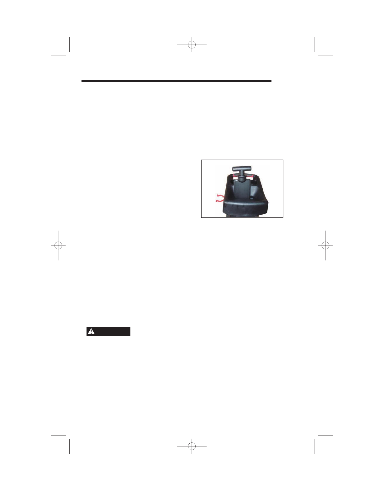
2. Turn the lock knob counterclockwise
until the housing cover can be
opened.
3. Lift up the housing cover to expose
the two blades
(1).
4. Place a 6 mm wrench (2) on one
of the four 6 mm bolts below the
blade support
(3) to secure it and
stop it from rotating.
5. Use the other 6 mm wrench to
loosen and remove the two
screws (5) that hold each blade to the support.
6. Lift out the old blade. Either reinsert the blade with the sharp edge in
position as the cutting surface or insert a replacement blade.
7. Replace and tighten the two screws to secure the new blade to the support.
GENERAL MAINTENANCE
1. Keep the chipper clean and in good repair for maximum performance and
machine longevity.
2. Before each use, inspect the switch and cord for damage.
3. Check for damaged, missing, or worn parts. Check for loose screws, moving
parts that are jammed or any other conditions that may affect the operation.
4. If abnormal vibration or noise occurs, turn OFF the tool immediately and
correct the problem before further use.
5. Do not use the chipper until it is properly repaired or replaced.
14
Fig. 9
2
1
3
4
5
ALWAYS TURN OFF THE TOOL AND UNPLUG THE
POWER CORD FROM THE OUTLET BEFORE MAINTAINING THE
CHIPPER.
MAINTENANCE
WARNING

• Wipe the outside of the chipper with a dry soft cloth.
• Remove the hopper from the housing body before washing the inside of the
hopper.
• Do not hose down or wash the tool with water.
TO AVOID INJURY, ELECTRIC SHOCK, OR DAMAGE
TO THE CHIPPER, NEVER ALLOW A LIQUID TO FLOW INSIDE THE
TOOL.
15
TO AVOID DAMAGE OR ELECTRIC SHOCK, DO NOT
USE STRONG SOLVENTS OR DETERGENTS ON THE PLASTIC
HOUSING OR PLASTIC COMPONENTS. CERTAIN HOUSEHOLD
CLEANERS MAY CAUSE DAMAGE AND MAY ALSO CAUSE A SHOCK
HAZARD.
MAINTENACE
WARNING
WARNING
CLEANING

16
LIMITED TWO-YEAR WARRANTY
The manufacturer warranties to the original purchaser that each new product and service part is free from defects in
material and workmanship and agrees to repair or replace under this warranty any defective product or part as follows
from the original date of purchase.
2 —Year Limited Warranty
THIS WARRANTY IS NOT TRANSFERABLE AND DOES NOT COVER:
Products sold damaged or incomplete, sold “as is”, sold reconditioned or used as rental equipment.
Delivery, installation or normal adjustments explained in the owner’s manual.
Damage or liability caused by shipping, improper handling, improper installation, incorrect voltage or improper wiring,
improper maintenance, improper modification, or the use of accessories and /or attachments not specifically recommended.
Repairs necessary because of operator abuse or negligence, or the failure to install, operate, maintain and store the product
according to the instructions in the owner’s manual.
Damage caused by cold, heat, rain, excessive humidity, corrosive environments and materials, or other contaminants.
Expendable items that become worn during normal use.
Cosmetic defects that do not interfere with tool functionality.
Freight costs from customer to vendor.
ANY INCIDENTAL, INDIRECT OR CONSEQUENTIAL LOSS, DAMAGE, OR EXPENSE THAT MAY RESULT FROM ANY
DEFECT, FAILURE OR MALFUNCTION OF THE PRODUCT.
Some states do not allow the exclusion or limitations on how long an implied warranty lasts, so the above limitations may
not apply to you.
WARRANTY REPLACEMENT PARTS are available by calling the toll free number, 1-800-444-6742, 8:00am – 6:00pm EST,
Monday-Thursday, 8:00 a.m.-5:00 p.m., EST, Friday.

PARTS LIST
17
1
2
3
4
5
7
8
9
10
11
12
13
14
15
16
17
18
19
20
21
22
23
24
25
26
27
28
29
30
31
32
33
34
35
36
37
38
39
40
41
42
43
44
45
46
47
48
49
50
51
52
53
54
55
56
57
58
59
60
61
62
63
64
65
66
67
68
69
70
71
72
73
74
75
76
77
78
79
80
81
82
83
84
85
6

18
PARTS LIST
1
2
3
4
5
6
7
8
9
10
11
12
13
14
15
16
17
18
19
20
21
22
23
24
25
26
27
28
29
30
31
32
33
34
35
36
37
38
39
40
41
42
43
44
45
1
1
1
1
1
1
1
1
2
1
27
1
1
1
1
2
4
1
5
1
1
1
4
2
1
1
1
1
1
2
4
1
1
1
1
1
1
4
1
1
1
1
1
10
2
Description Item Qty
Upper handle
Lower handle
Warning label
Feeder hopper
Flat push stick
Flap
Spring
Steel ball
Push stick holder
Clamp block
Screw
Washer 5
Upper housing
Up housing
Bolt frame plate
Screw
Spring washer 2
Switch pin
Hex type screw
Screw
Spring washer 1
Clamp block
Hex nut
Blade
Blade plate
Drive block
Blade cover plate
Latch rod
Washer 3
Hex nut
Screw
Lower housing
Knob
Spring
Retaining ring
Fixup nut
Nut frame plate
Hex nut
Overload swtich
Supply cord
Cord sheath
Cord clamp plate
Switch frame plate
Screw
Screw

19
PARTS LIST
46
47
48
49
50
51
52
53
54
55
56
57
58
59
60
61
62
63
64
65
66
67
68
69
70
71
72
73
74
75
76
77
78
79
80
81
82
83
84
85
1
1
1
1
1
1
1
1
1
1
1
2
1
1
2
1
2
1
1
1
1
1
2
1
1
1
1
1
1
1
1
1
1
2
3
1
1
1
2
2
Description Item Qty
Sponge
Connecting wire 1
Connecting wire 2
On/Off switch
Trip switch
Label
Motor housing
Capacitor
Fan
Bearing sheath
Bearing
Screw
Motor support
Field
Screw
Right hook clip
Hook
Armature
Bearing
Small belt wheel
Left hook clip
Wind defend board
Plastic pin
Lower gearbox cover
Bearing
Eccentric wheel
Rolling wheel
Washer 4
Big belt wheel
Belt
Upper gearbox cover
Bearing
Hex wrench
Hex nut
Washer 1
Leg stand
Axle
“L” wrench
Washer 2
Wheel
 Loading...