

Page 1

2012.3. 8 Revised
3.16Revised
3.19Revised
3.21Revised
4. 6 Revised
8.30 Revised
2013.11.18 3rd Edition
3500i/4500i/5500i/6500i/8000i
Troubleshooting Guide
1
Page 2

Content
2
Item Phenomeno
3500i/4500i/5500i 6500i/8000i Pages
Image Toner Color Dot / Color Mark
○ ○
4-5
Void Li ne / White Band
○ ○
6-9
Void Li ne / Blac k Band(V ertical B l ack S t ri pes)
○ ○
10
Image Smudges
○ ○
11-23
Light Image
○ ○
24
Edge Part Background
○ ○
25
Meas ure for Condensat i on
○ ○
26
DP-770 Tip50mm・End37mm Character B l urring
○
27-28
Conveying
J0501~7 / J0523~7
○ ○
29-30
J051X
○ ○
31
J05X8/J44XX
○ ○
32
J0545 (PF-770)
○ ○
33
PF-770 Repair for the procedures s l ope c onfirm ation of TRAY PAPE R
○ ○
34
J1313 / J1314
○ ○
35
J150X/J1904
○ ○
36
J1512
○ ○
37
J341X(PF)
○ ○
38
J4103/ J4104
○ ○
39
Abnormal Sound/ J42XX/J40XX( Add Interme di ate Motor Cover)
○
40
J42XX/Fixi ng S e paration Claw Tip Missing or Damaged
○
41
J421X / J460X / J470X
○ ○(J460Xのみ)
42-43
Torn Paper、J430X/431X/440X/471X, 60m m from bot tom edge
○
44
○ ○
45
J49XX / J50XX / J51XX / J600X
○ ○
46-54
J610X / J611X (DF)
○ ○
55-60
J631X / J641X / J650X (DF)
○ ○
61-63
J6510 (DF-790 Caution of Manual S ta ple)
○ ○
64
J6600 (DF)
○ ○
65
J6710 / J7710 (BF)
○ ○
66
J9020/J9030
○ ○
67
J9010 / J9011 / J9110 / J9300 / J9310 / J9400 / /J9600 / J961
○ ○
68
Dog Ears
○ ○
69-74
Paper W ri nkles
○ ○
75-76
BF-730/720/710 P a per Wrinkle Correspondence of 1 Sheets of Paper
Whe n Fol ded in the Middle
○ ○
77
Page 3

Content
3
Item Phenomeno
3500i/4500i/5500i 6500i/8000i Pages
C-CALL C0640
○ ○
78
C2101
○ ○
79
C2201
○ ○
80
C510X
○ ○
81
C6000/C6030/C6050/C6200/C6230/C6250
○
82
C6020/C6220
○
83
C6020/C6030/Fix ing Roll er Fusing, Poor Fix i ng
○
84
C6030/C6050
○
85
C6600/C6720/F ixi n g Belt Da mage
○
86-90
C6620
○
91
C6730
○ ○
92
C6770
○
93
C6910
○ ○
94
C7101
○ ○
95
C9500/C9510/C9520/C0630/C0640/CF245 SATA Cable Fai l ture
○ ○
96
CF000/“Welcom e” S creen Lock
○ ○
97
CF040
○ ○
98
CF182/186
○ ○
99
Abnormal S ound F rom Developing Unit
○ ○
100
Abnormal S ound F rom F i x i ng Dri ve Unit
○
101-105
DP Mot or Dri ven Sound
○ ○
106
Others DP Si ze Detec t i on Error
○ ○
107
Disporsal Toner Bott l e
○
108
Time for maintenance.(T)
○ ○
109
Damage of Cassette Rail
○ ○
110-111
Abnormal
Sound
Page 4
4
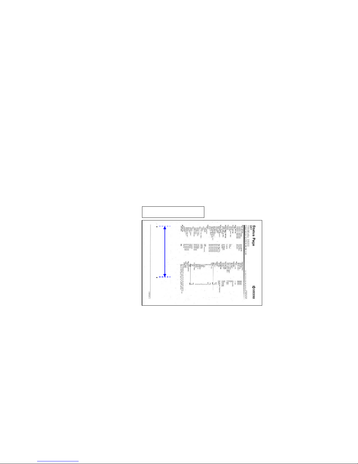
Black Dot / Black Marks
Image sample 1
1.126mm interval Black Dots (drum)
If one of several 126mm interval black dots appears randomly at sub scanning
direction, take the following measure.
(Image sample 1)
(*there is the case that the black dots appearance becomes vertical line.)
a.Replace the DRUM ASSY (DK-6305/6705).
126mm
Page 5
Black Dot / Black Mark
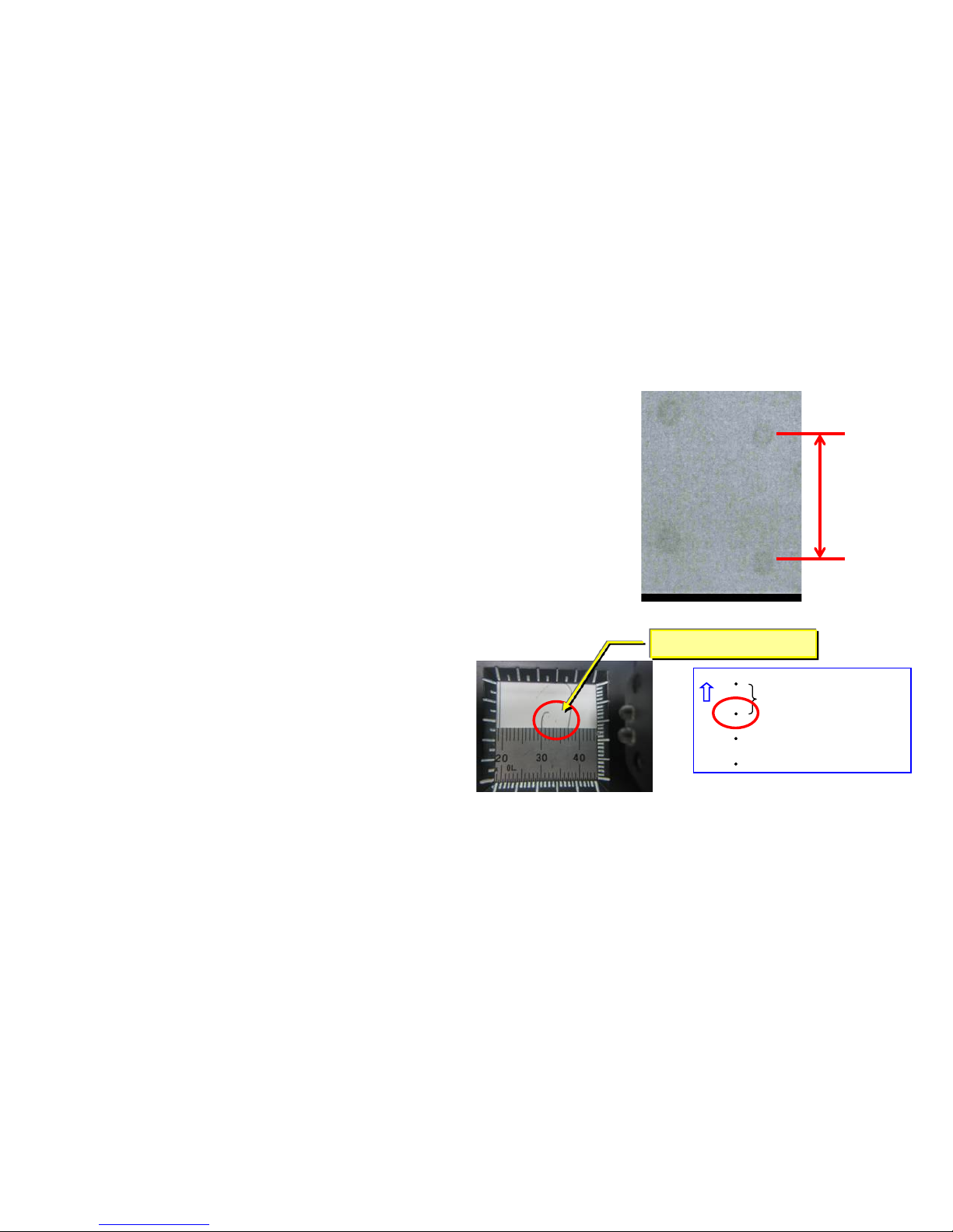
2. 45mm interval Black dots
If 45mm interval paper appears at image in the sub
scanning direction, tak e the following measure.
a. Check whether the foreign subst ance are attached
on the developing roll er surface.
b. If the foreign substance attached, wipe off by the
clean cloth.
c. If no foreign substance attached or it will not be
disappeared after w iping off, replace t he devel oping
unit.
Image
φ0.1~0.3mm
45mm
Above is to check the
black dots on the paper
by the Magnifying glass.
1. 38mm interval black dots, black marks (Charger r oller)
Take the follow ing measure if the 38mm inter v al bl ack dots or marks appear
at the image In the sub scanning direction.
a. Check the 38mm interval to print out the test sample by U089 M ono4.
b. Replace the MC-6705 after confirming the dots appears 38mm inter val .
c. Execute U930 charger roller counter reset after replacing MC-6705.
38mm
5
Page 6
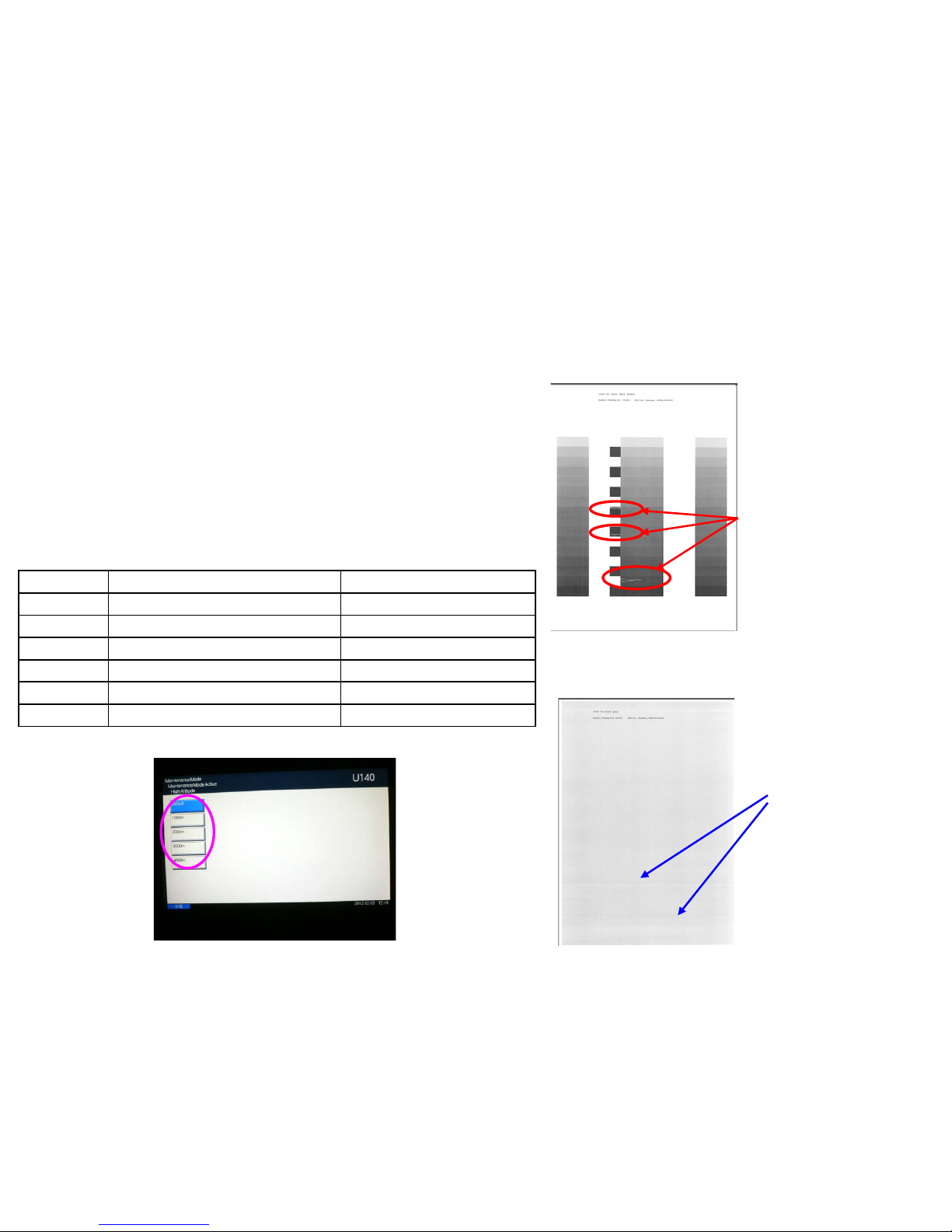
a. If the void image appear at solid part of prints out on U089 Color
Belt, refer to below “b” * If the vert ical streak image appear s at the
halftone, replace the dev elopi ng unit.
b. Execute U140 AC Calib High Altitude
c. Select “Altitude” and find the setting w hich the leak image does not
appear . * Avoid the setting far from the actual al ti tude.
d. If the image will not be recovered, replace the developi ng uni t.
Image sample 1
◇ Leak at the solid part
Void image appear at the solid part.
U89 Sample set
Void imag e at
Solid part
Image sample 2
◇Leak at the halftone par t
Horizontal streaks appear at Halftone image.
U89 Sample set
Horizontal streaks
at halftone image
Void Line / White Band (Horizontal White Streaks)
1. Leak Image 1 (3500i、4500i)
Execute AC Calib Operation Autom atically
Select AC Calib High Altitude Setting
7550ci/6550ci
O
5550ci/4550ci
O
3550ci/3050ci
O
8000i/6500i
O
5500i
O
4500i/3500i
O
6
Page 7
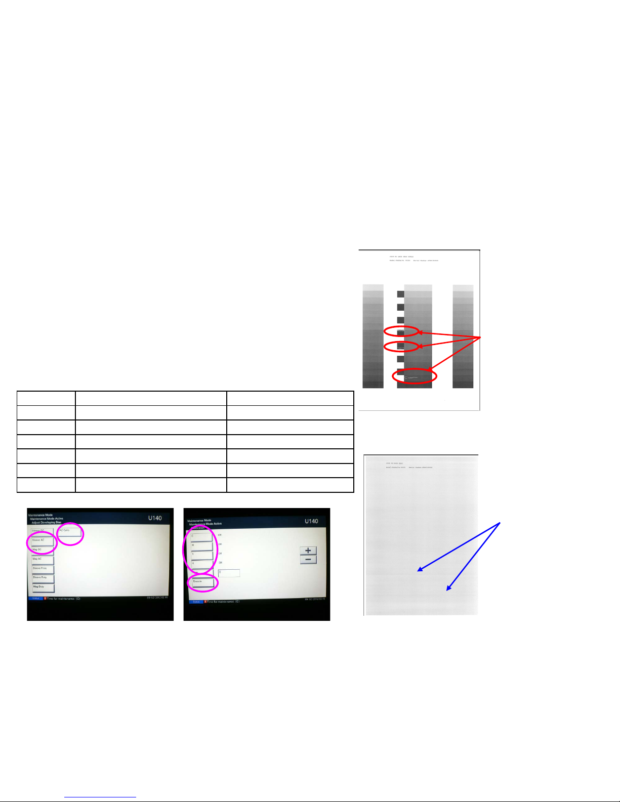
a. If the void image appear at solid part of prints out on U089 Color
Belt, refer to below “b” * If the vert ical streak image appear s at the
halftone, replace the dev elopi ng unit.
b. Check the value of U140 Sleeve AC (1)
c. U140 Execute AC Calib(2) Set “K” Off to
On(3) Execute(4) Start
d. Check whether the value of U140 Sleeve AC (3) becomes lower
and the image is recovered.
e. If the image will not be recovered, replace the developi ng uni t.
(3)
(4)
(1)
(2)
Image sample 1
◇ Leak at the solid part
Void image appear at the solid part.
U89 Sample set
Void imag e at
Solid part
Image sample 2
◇Leak at the halftone par t
Horizontal streaks appear at Halftone image.
U89 Sample set
Horizontal streaks
at halftone image
Void Line / White Band (Horizontal White Streaks)
1. Leak Image 2 (5500i、6500i、8000i)
Execute AC Calib Operation Autom atically
Select AC Calib High Altitude Setting
7550ci/6550ci
O
5550ci/4550ci
O
3550ci/3050ci
O
8000i/6500i
O
5500i
O
4500i/3500i
O
7
Page 8
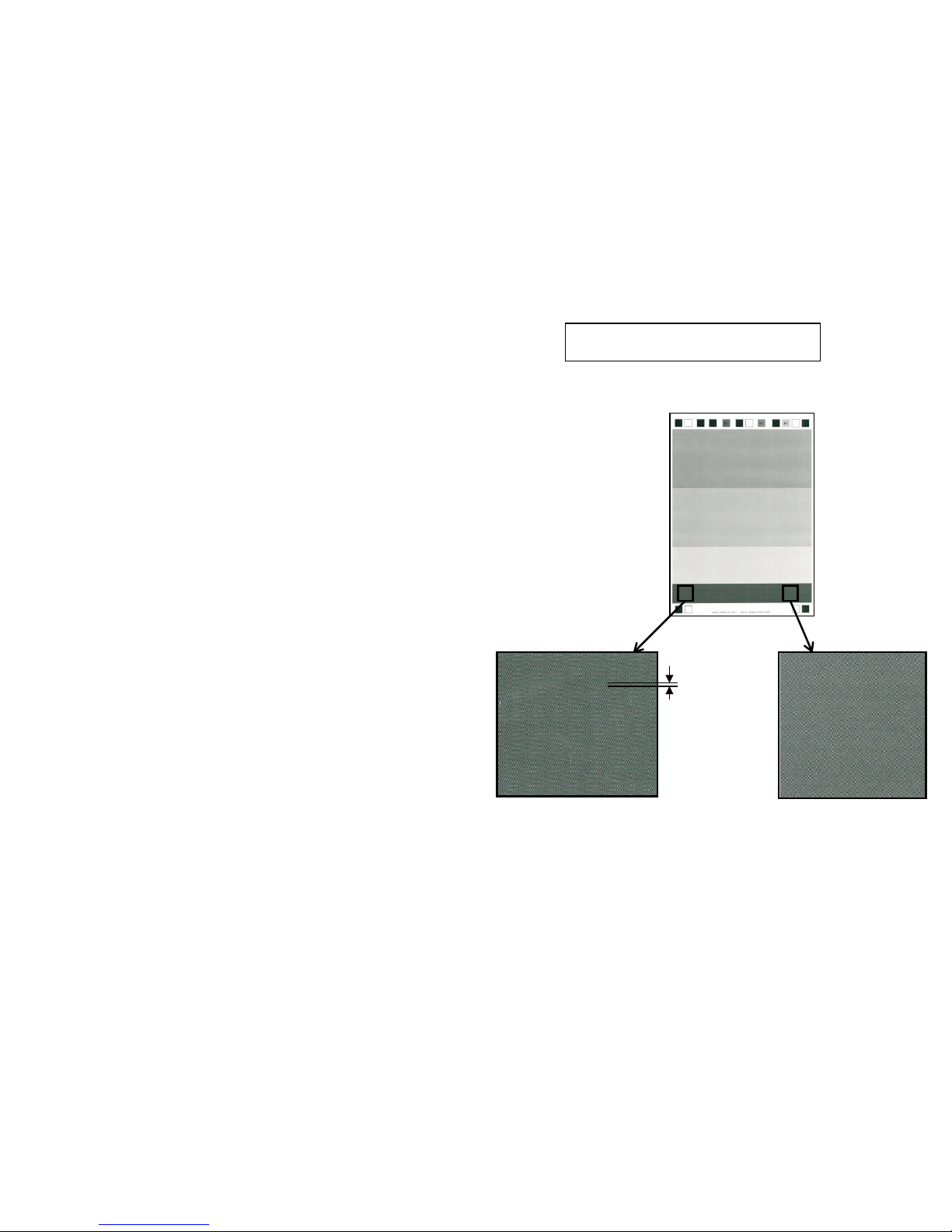
Void Line / White Band
2. Horizontal white streaks (Image sample 1)
If 1.2mm interval horizontal streaks occur at
the gray image in the main scanning
direction, take the following measure. *In
case of this appearance at the machine’s
rear side is more noticeable than at front.
a. Replace the LSU.
Image sample 1
About
1.2mm
Machine
Front
Machine
Rear
8
Page 9
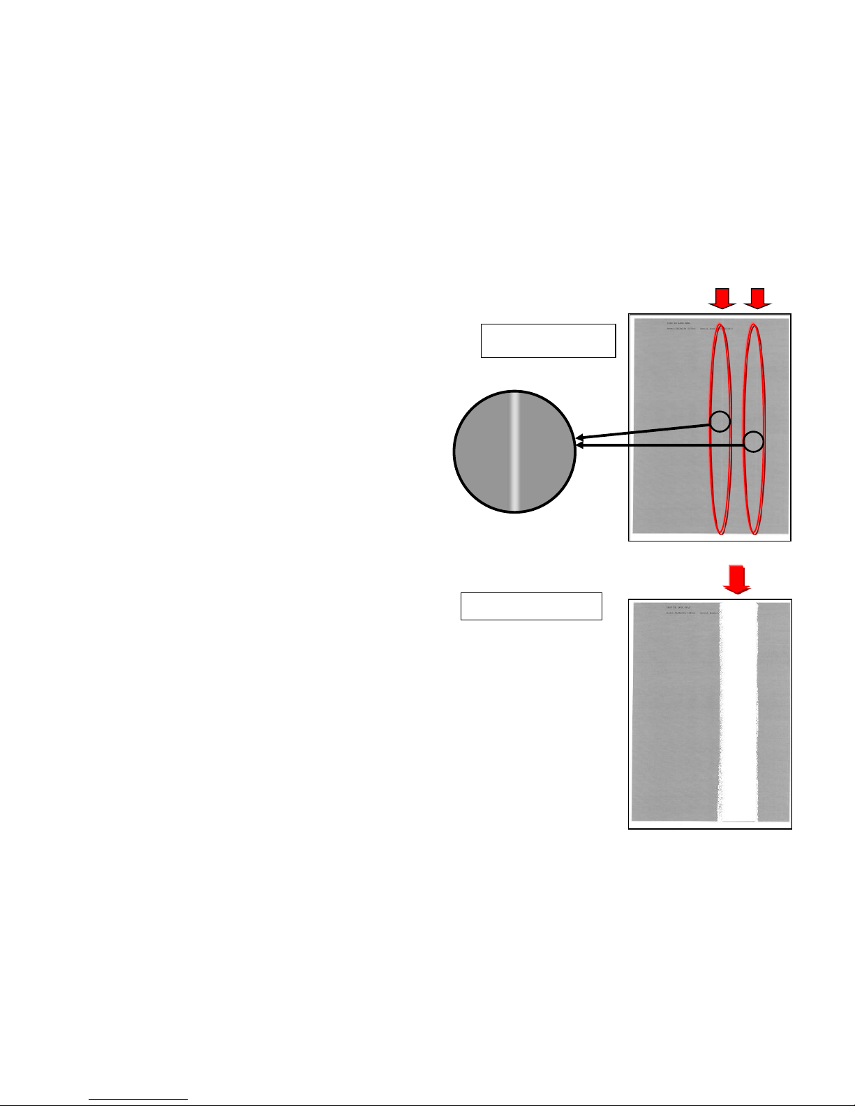
Void Line / White Band
3.Vertical White streaks (Image sample 1)
If vertical white streaks appears continuously and
linearly in the sub scanning direction, take the
following measure.
a. Clean the cover glass on the LSU.
Image sample 1
Verti cal whi te streaks
Image sample 2
4. Vertical White lines (void image) (Image sample 2)
If the void image appears by wide width in the sub scanning direction, take
the following measure.
a. Replace the LSU. (In case of the machine is produced before 2011 Oct.)
9
Page 10
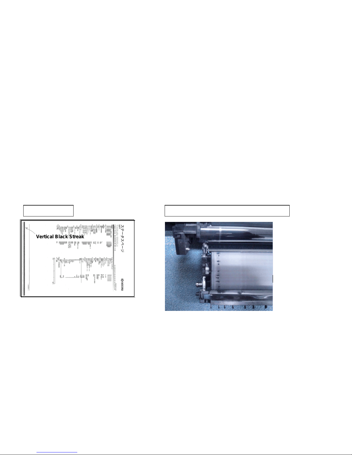
1. Vertical Black streaks (Image sample 1)
It occurs continuously and linearly toward the paper feeding direction.
Please remove the transfer belt unit and check whether the transfer belt is cracked.
1. When the transfer belt is torn or cracked, please replace the drum unit and the transfer belt unit.
2.Check the firmware version (U019) and upgrade it higher than Upgrade Pack Ver. V4.00
Image sample 1
Void Line / Black Band
Vertical Black Streak
Condition of tear or crack on the transfer belt
10
Page 11
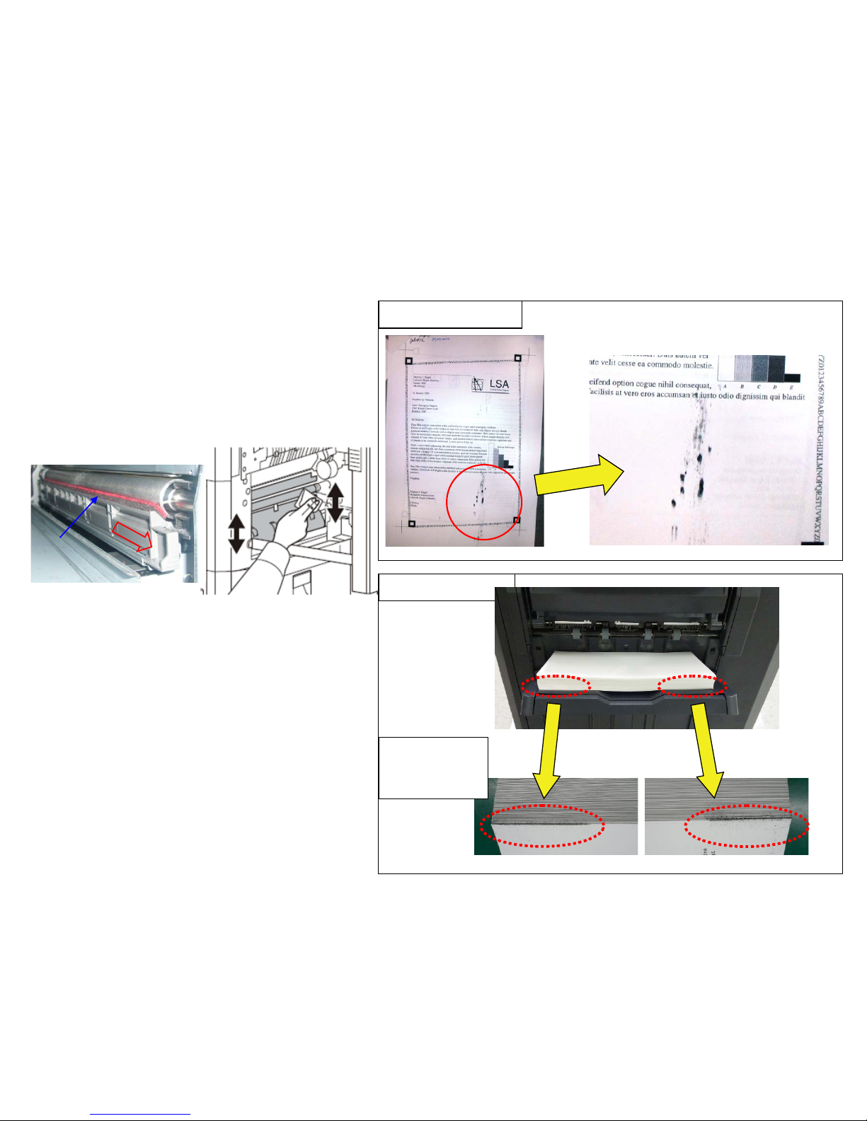
Image Smudges (1/13)
Image sample 2
View from
bottom part of
ejected paper
2.Image Smudges (Imag e samp le 2)
The smudges appears at the leading edge of ejected
paper.
Clean the duct at insi de i f machine and the
developing unit.
Refer to “3.Cleaning Procedure” for cleaning.
1.Image Smudges (Imag e samp le 1)
There is no periodicity and it occurs intermittently
in the paper conveyance direc tion.
a. Clean the conveying guide.
b. Clean the paper dust cleaner at the regist roller
section.
(-->)
Image sample 1
Cleaner
11
Page 12
(Stains on the conveying guide)
The stains occur at the outside of paper path.
3. Cleaning Procedure
Image Smudges (2/13)
a. Preparation before cleaning
Remove the lower rear cover and toner box
(Fig.1)
Remove the developing unit and dr um unit
after detaching the inner unit .
Remove the toner box.
2 screws
Fig.1
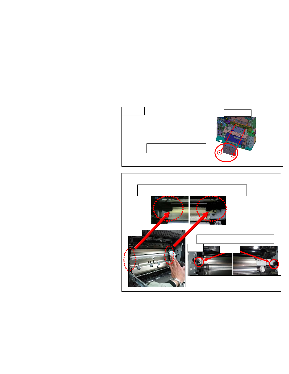
b. Clean the conveying guide .
Clean the paper feeding si de of the
conveying guide ( Fig .2)
At the nex t, r emove the conveying guide
(one each at front and rear), clean the back
side of conveying g ui de ( F i g .3)
* For cleaning, use the dr y and soft cloth. (It
locates at the size indi cati on plate slot on
1st cassette.)
Clean the conveying guide
Screw
Fig.2
Fig.3
12
Page 13
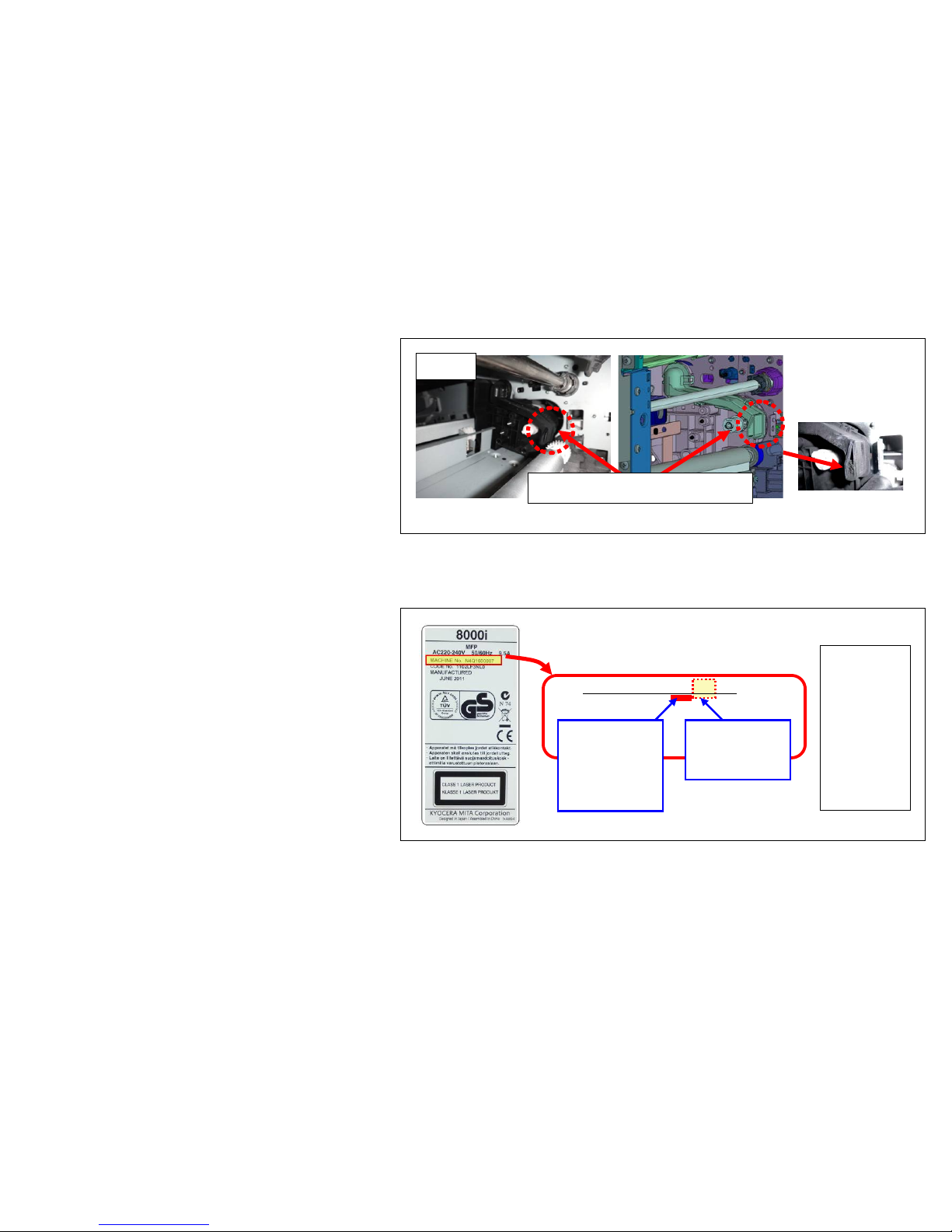
Image Smudges (3/13)
c. Clean the toner exhaust duct at inside of
machine
While the developing unit is taken out and the
conveying guide i s removed, suct ion t he toner
exhaust part at inside the machine where the
toner exhaust duct of the developing unit
connected with a cleaner. (Fig.4)
Note) Clean while paying attention not to scratch the gear and registration roller.
(Before
cleaning)
Tone is
accumulating.
(-->) T oner Exhaust Aperture
Fig.4
d. Check the machine’s production month
Check the production month from the
machine’s serial number on the rati ng l abel and
clean it according to the production month.
・Before 2012/Feb. production machine.
Refer to the cleaning procedure “e”
”g”
・After 2012 / Mar. pr oducti on model.
Refer to the cleaning procedure “f”
“g”
MACHINE No. N4P22*****
16 : 2011/6
17 : 2011/7
18 : 2011/8
19 : 2011/9
1X : 2011/10
1Y : 2011/11
1Z : 2011/12
21 : 2012/1
22 : 2012/2
23 : 2012/3
24 : 2012/4
25 : 2012/5
(Rating label)
(Way of refer to the
production month)
N4P:Model
Number
It differs
according to
the model
22:Indicate
2012 Feb.
production
13
Page 14
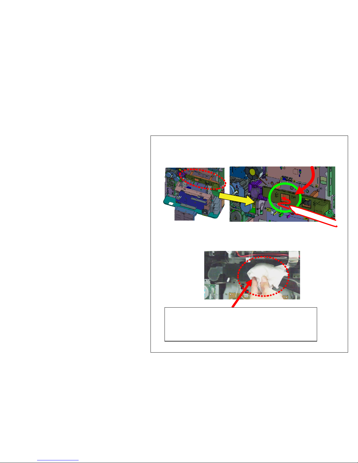
Image Smudges (4/13)
e. Clean the DUCT TONER UNIT
( In case of 2012 Feb. production machi ne)
Clean the DUCT TONER UNIT with the vacuum
cleaner.
Procedure 1) Clean and suction the outlet of duct with
cleaner for 1 min.
A cleaner ti p is put in and attracted from this direction.
(If a opening is cover ed with a rag etc. so that the open
air may not be attracted from a cleaner tip, toner can
be attracted effectively.)
14
Page 15
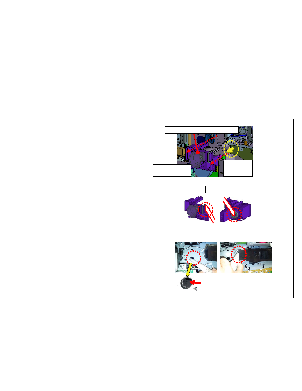
Image Smudges (5/13)
Procedure 2)
Remove the 302LF33012/DUCT FAN TONER
from the machine and clean, suction it with the
vacuum cleaner.
Reattaching the seal after cleaning and cut the
part of duct.
302LF33012/DUCT FAN TONER
Remove the duct
with 2 screws
Lift up this
part if it is
detached.
Clean the removed duct
Clean after removing the duct too.
(Before cleaning )
Toner is accumulating.
15
Page 16
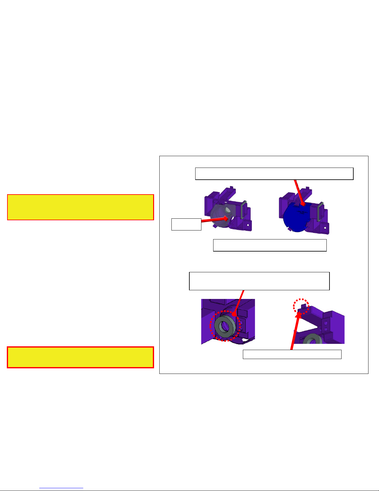
Re-attach with 302LF33201/SEAL TONER
DUCT A (Chang e wi th 5mm thick sponge)
Cut the rib (claw) of the duct.
Procedure 3)
Peel off the FILM of 302LF33012/DUCT FAN
TONER and replace w ith 302LF94410 /PAR TS LID
TONER FAN ASSY(ZG) SP
302LF94410/P AR TS LID TONER FAN ASSY(ZG) SP
FILM
302LF94410 is re-usable.
After this replacement, the level of unit is same
as 2012 Mar. and after production model.
Please replace with the parts as shown in fig when
302LF94410/PARTS LID TONER FAN ASSY(ZG)
SP.is available.
Image Smudges (6/13)
16
Page 17
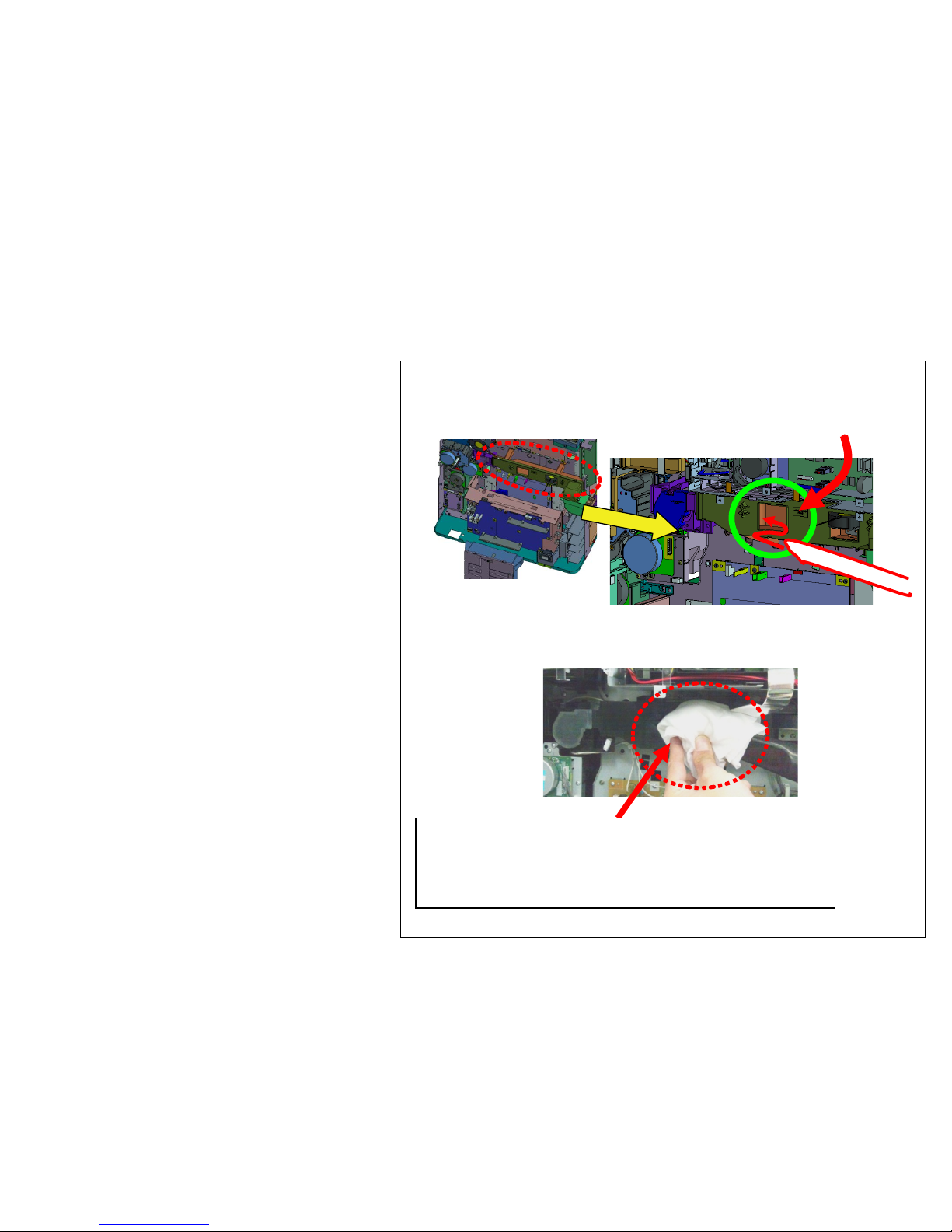
f. Clean the DUCT TONER UNIT
(In case of 2012 Mar and after production
machine)
Clean suction the DUCT TONER UNIT with
the vacuum cleaner.
Procedure 1) Clean suction the duct outlet for 1 min with
the vacuum cleaner.
A cleaner ti p is put in and attracted from this direction.
(If a opening is cover ed with a rag etc. so that the open
air may not be attracted from a cleaner tip, toner can be
attracted effectively.)
Image Smudges (7/13)
17
Page 18
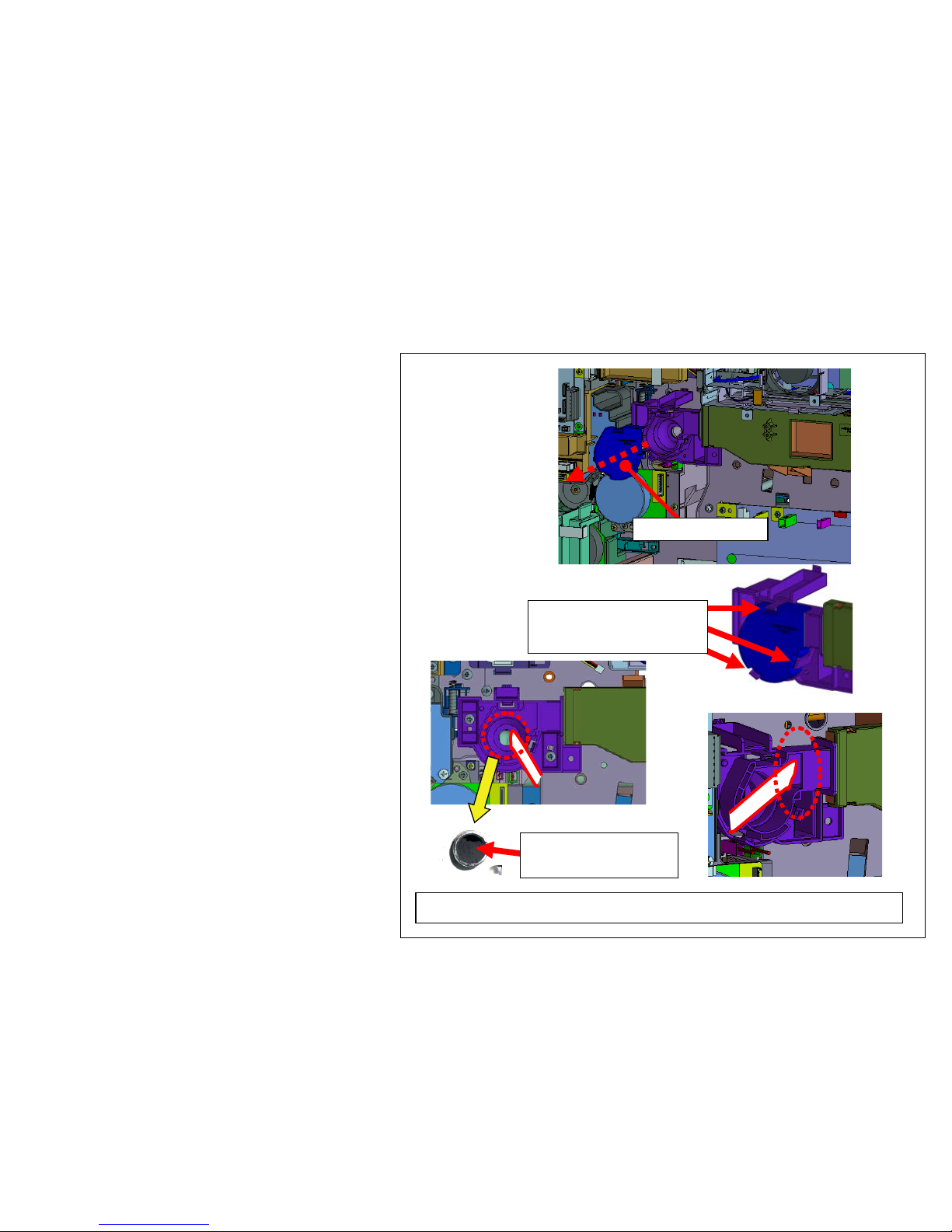
Procedure 2)
Remove the 302LF33830/LID TONER FAN from
the machine and clean suction it with the vacuum
cleaner.
(Before cleaning )
Toner is accumulating.
LID TONER FAN
Remove it after releasing 3
pcs of snap-fit
Return the LID TONER FAN at ori g i nal posi ti on after cleaning
Image Smudges (8/13)
18
Page 19
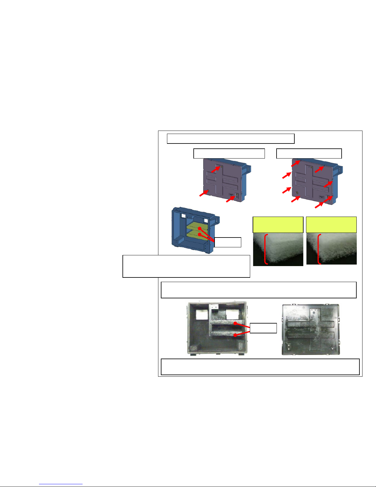
(-->)
g. Replace the DISPOSAL TONER UNIT.
- Replace the following DISPOSAL TONER UNIT.
302LF94400 PARTS DISPOSAL UNIT(ZG) SP
- Clean suction the acc umulating toner at the
DISPOSAL TONER UNIT inside or the FILTER.
Refer to the right figure for the c l eaning
procedure.
( FILTER )
302LC33240/FIL TER OPTION A (New type)
302LF33820/FILTER TONER (Old type)
Remove the LID from the DISPOSAL TONER
Old type (2 piles
sheets)
New type (2 layer
structure)
Clean the inner part of accumulating toner and filter after opening the DISPOSAL
TONER UNIT.
When cleaning the old type Filter, Be careful for FILTER of the thinner side not to
be inhaled by the cleaner due to two-sheet piles.
FILTER
FILTER
Remove 3 pcs of screws Release 8pcs of snap-fit
Install the thick density side of FILTER at Fan side
with (both sheets). There are not difference in
performance between old and new 2 type of filters.
Image Smudges (9/13)
19
Page 20
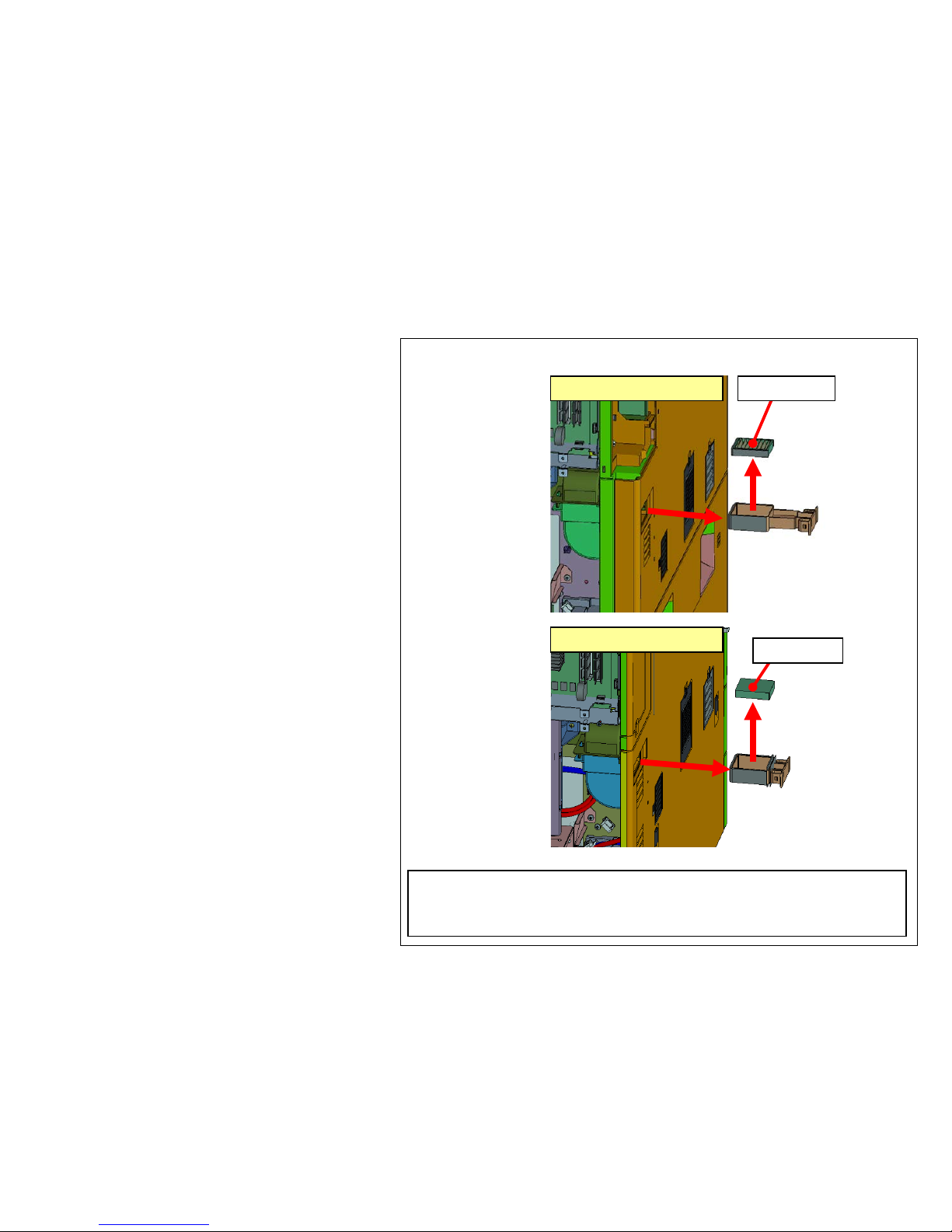
FILTER 2
FILTER 2
6500i/8000i
3500i/4500i/5500i
At cleaning the FILTER, the FILTER can be detached after removing
the DF Rear Cover without releasing D F from the main body.
After removing, clean or replace i t.
h. Clean the FIL TER
( FILTER )
302LC33370/FILTER LEFT SIDE
Image Smudges (10/13)
20
Page 21
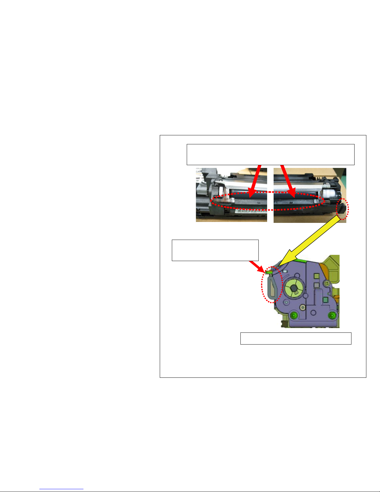
i. Clean the developing unit
Clean the toner stain on t he r emov ed
developing unit.
(-->) Absorb the insi de toner w hile fitting the
nozzle of the vacuum c leaner to the
toner waste aperture of the DUCT.
Clean the accumulating toner on the toner r eceiv er of the
developing unit.
At rear side of the developing unit
Clean the toner at inside of
developing cooling duct
Image Smudges (11/13)
21
Page 22
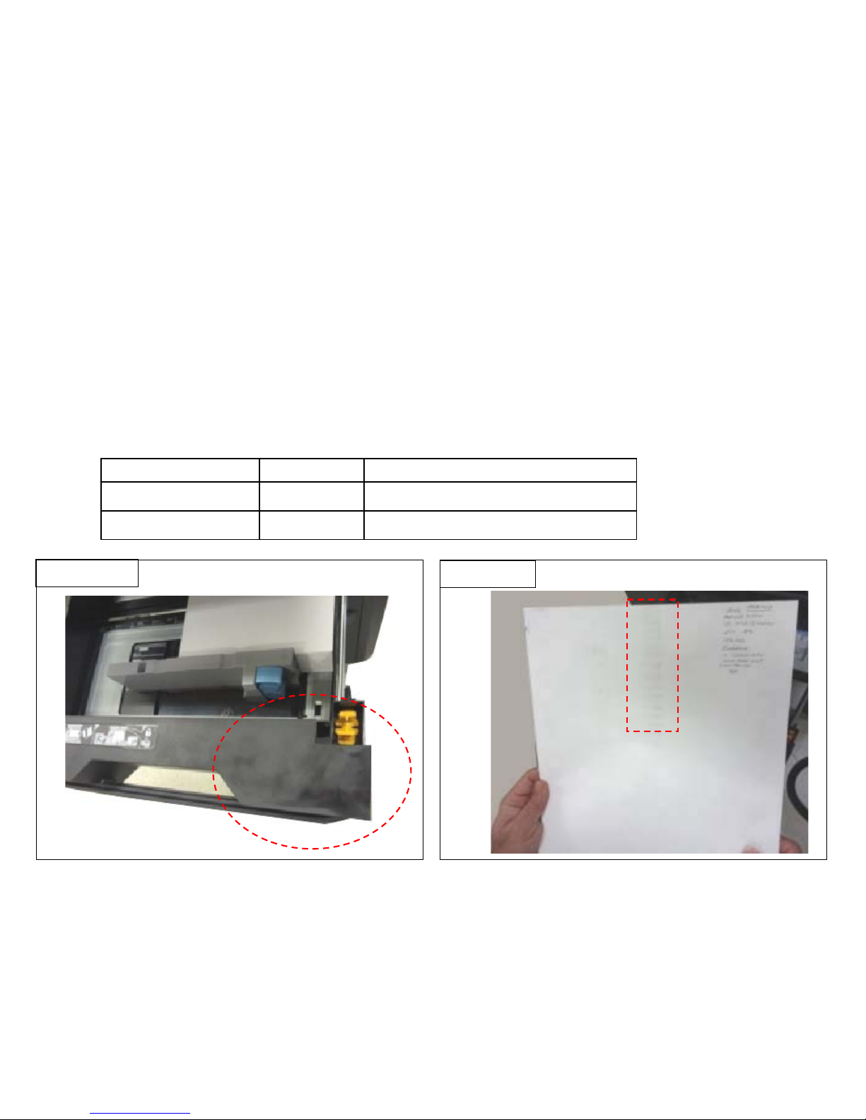
Image sample4
Image sample3
4.Image Smudges (Image sample 4)
Toner smudges at the 1st cassette (Image sample3)
Toner smudges by the feed pulley when feeding the paper from the 1st cassette (Image sample4)
a. Clean the duct at inside if machine and the developing unit.
*Refer to “3.Cleaning Procedure” for cleaning.
b. Please use the PARTS SEAL SET.ALL SP.
*Refer to the service bulletin No. 2LF-0014(C171) for the detail information
Model Part No Description
8000i/6500i 302LF94451 PARTS SEAL SET ALL SP
5500i/4500i/3500i 302LH94341 PARTS SEAL SET ALL SP
Image Smudges (12/13)
22
Page 23
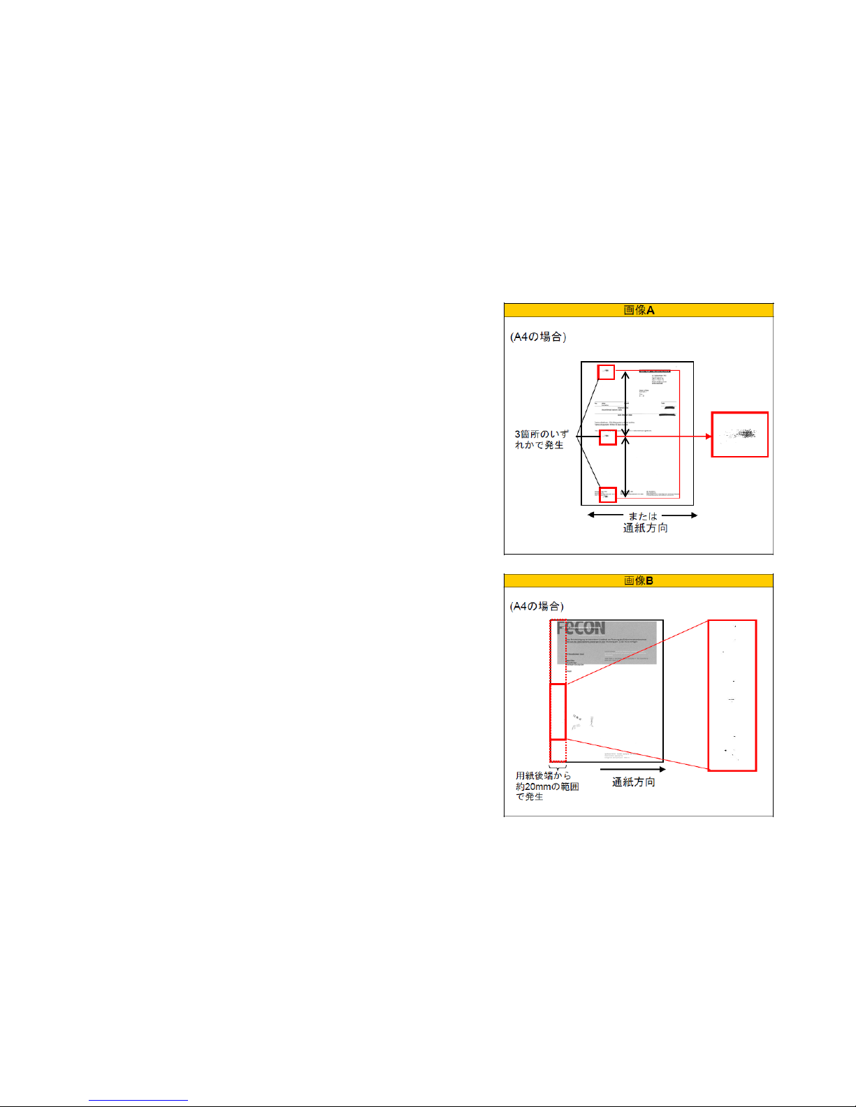
128mm
118mm
Toner stain・Bottom edge toner stain
5. Toner s tai n occ urs at the pos i ti on shown in the right fig, pleas e
take the following measure. ( imag e sample A)
2. When toner stain occurs at about 20mm position from paper
bottom edge, please take the following measure. (image sample
B)
a. Replace the DV unit. ( DV-6305/6705:
302LH93034/302LF93034)
a. Replace the DV unit. ( DV-6305/6705:
302LH93034/302LF93034)
Image A
Image B
Feeding direction
Feeding direction
(In case of A4)
(In case of A4)
It occurs in
three
places of
either
It occurs in the
range of about
20mm from paper
bottom edge.
Image Smudges (13/13)
23
Page 24
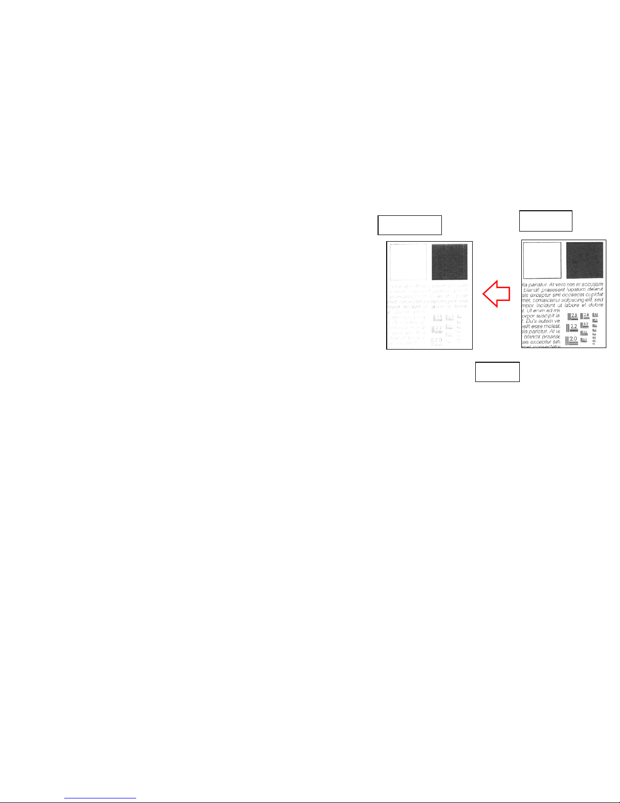
Light Image
If the copy image becomes out of focus, take the following measure in
order. (Sample1)
1. Replace the ISU_LENS UN IT (P ARTS IMAGE SCANNER L SP:
302K993082)
2. Execute the scanner auto adjustment.
2-1. Place the designated adjustment original (Part No.:
7505000005) on the contact g lass .
2-2. Select “Targ et” on U 411 S canner Auto Adjustment
2-3. Select “Auto” and pr ess the s tar t key.
2-4. Select “Table (Chart1)”.
2-5. Select “ALL” for items to be ex ec uted.
2-6. Press the start key and start the auto adj us tment.
Refer to the service bull eti n No. 2LC-0026 (B314)
Original
Sample1
COPY
24
Page 25
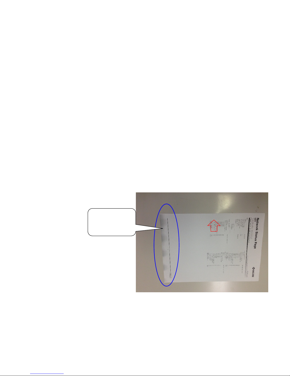
Edge Part Background
1.If Paper Edge Background occurs, you will be required of the following as below.
■ Case of failure
During the continuous output, event does not occur until a few sheet of papers, but it may occur in the middle.
The uneven density appears periodically at background image with developing sleeve pitch..
3500i/4500i/5500i/6500i/8000i:45mm
■ How to Respond
Check the Firmware and Upgrade to the Ver. 5.00 or above.
Please run the calibration after upgrade it.
End Background
occurs in the
magnetic roller
pitch
Sample 1:Case of failure (Monochrome Machine)
25
Page 26

Measure for condensation
<Phenomenon>
Flowing image occ urs at pr i nti ng after power on if the inside machine is in cold condition. ( condens ati o n
image occurs)
<Method of measure>
1.Update the firmware abov e Pack.3. 07
2.Change refresh freq uency (mode) of U148
3.If the condensation occurs easily depends on installation environment (the temperature difference in the
morning and day time is too large and high humidit y ) , set mode 2 in U148.
4.Set to Mode 3 if the condensation can not be eliminated at mode 2.
* Caution
Refresh frequency will be increased if incr ement of mode number. Therefore, if it is pointed out that the
warm up period becomes longer, set to mode 1.
However , the ef fecti veness of this measures dec r eases in comparison with Mode2 in the case of set
Mode1, please ask the user understand to perform refresh operation manually at the time of the
condensation occurs.
Mode Inner humidity <70% 70%≦ Inner humidity <80% 80%≦ Inner humidity <90% 90%≦ Inner humidity
0 0 time 0time 0time 0time
1 0 1 2 3
2 0 2 3 4
3 0 4 5 6
⇒Recomm
ended
Refresh frequency in each mode
26
Page 27
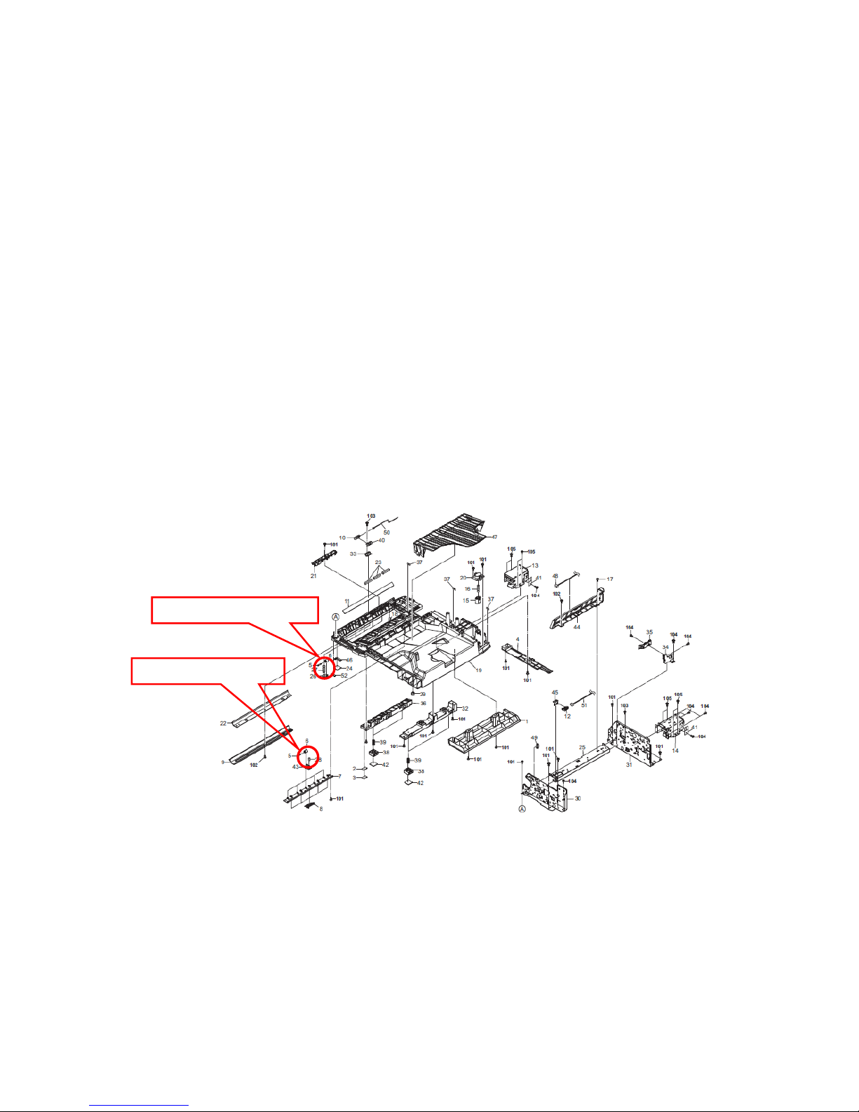
DP-770 Character blur at 50mm l eadi ng edge,
37 mm bottom edge
<Phenomenon>
Text Character is extended around 50mm from original leading edge and 37mm from bottom edge.
<Method of measure>
Change the front and rear nip pressure at scanning the original during DP conveying and stabilizing
the original conveying speed.
1.Change of the front nip pressure 1700g → 1200g 《Cut two coils》
Item 303LL24120:SPRING PULLEY CONV LEFT
2.1.Change of the rear nip pressure 900g → 500g 《Cut two and a half coils》
Item 303LL24130:SPRING PULLEY CONV R
1.Front scan spring
2.Rear scan spring
For 3500i/4500i/5500i
27
Page 28
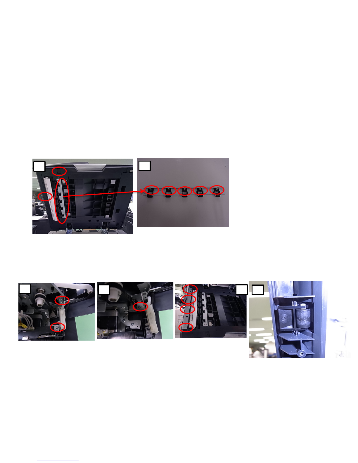
DP-770 Character blur at 50mm l eadi ng edge,
37 mm bottom edge
<Procedure for modification
1. Detach the original mat and remove 6 screws (1screw for front cover left lower, 1screw for left cover,
4screws for scan rear sprint mount plate)
2. All of 5pcs springs at rear original scan are cut two and a half coils.
1
2
3. Remove the rear cover and left side stay by 2screws, then remove the screws in the bottom of it.
4. Remove the lower cover while sliding front side, then remove the metal plate by 4 screws.
5. Remove all of original scan front pulleys (5 pcs) and springs (3303LL24120:SPRING PULLEY CONV
LEFT)are cut two coils.
6. Return it original position and execute DP feeding and DP scanned image checking.
3
3 4
5
For 3500i/4500i/5500i
28
Page 29
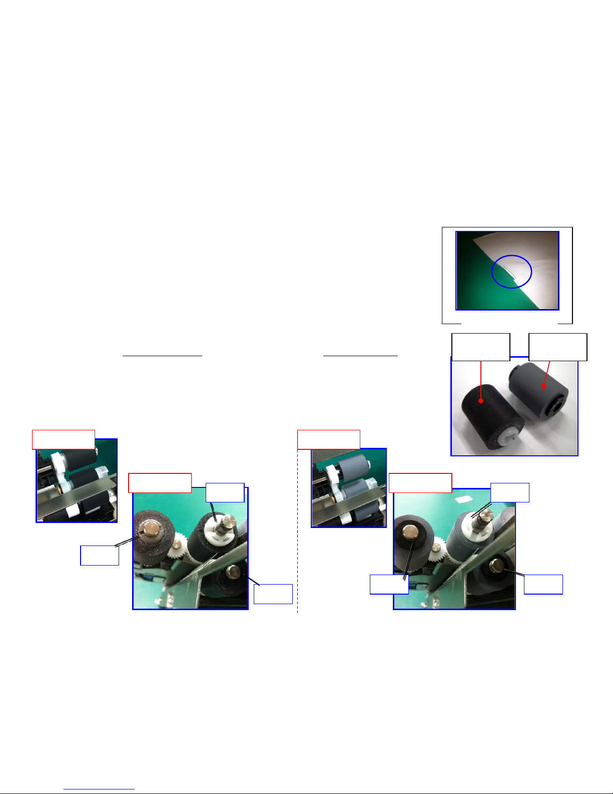
J0501 to 7 / J0523 to 7 (Misfeed JAM)
If above code display, take an action as referring to below procedure.
a. If JAM paper or printout paper is like a Fig.1, replace the Roller of the Primary Feed.
* The maintenance cycle for Primary Feed is 150K.*
b. Please adjust the pressure of the retard pulley based to the flow chart in next page if misfeed
occurs.
Affected Model :4500i,5500i,6500i,8000i
◆ Note ---- * Check the color of Roller to find the Old and New difference at the Primary Feed.
*Rubber color : Black *Rubber color :Gray
・Feed-Roller 302K906350 PULLEY FEED 2AR07230 PULLEY SAPARATION
・Retard-Roller 302K906360 PULLEY RETAR D 302K906340 PULLEY RETARD
・Pickup-Roller 302K906370 PU LLEY PICKUP 302K906340 PULLEY RETARD
Refer to the service bulletin No. 2LC-0003(B105) for the detail information for Roller.
Fig.1 JAM Paper
Rubber
color :Black
Rubber
color: Gray
NEW OLD
NEW OLD
Gray
Black
White White
Black Black
J0501 to 7 / J0523 to 7
( Misfeed)
29
Page 30
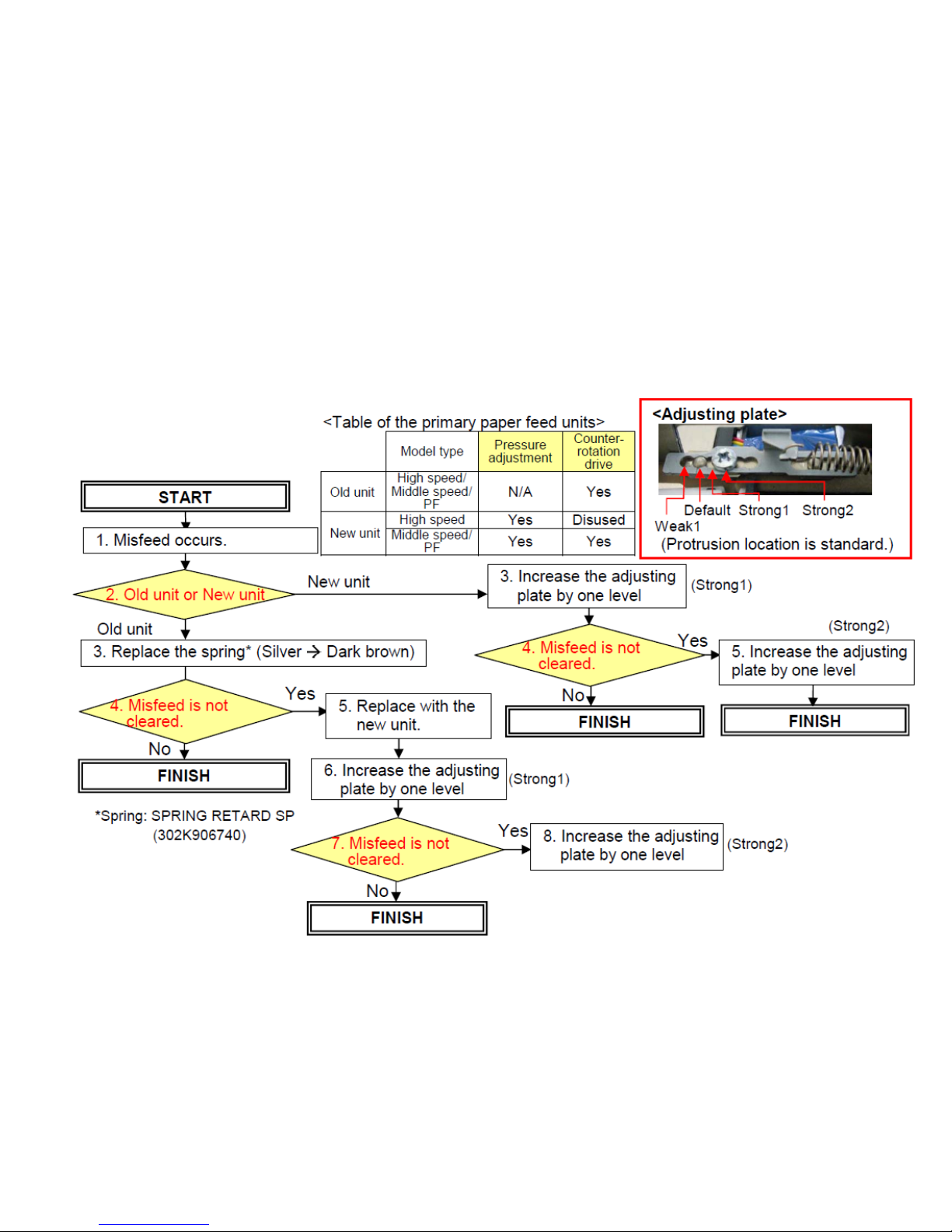
[Procedures for adjusting the pressure of the retard pulley (Flow chart)]
Refer to the service bulletin No. 2LF-0015(C191) for the detail information
J0501 to 7 / J0523 to 7
( Misfeed)
30
Page 31
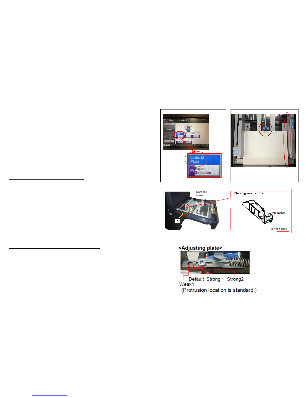
J051X Continuous Feeding JA M
If J051X occurs, take an action as referring t o below
procedure.
a. Check the paper size (Fig.1)
Check whether the size of paper is set at the cassette and stated on
the JAM log of the Even Log is same or not.
If the paper size is different at “a”
b. Check whether the position of cassette cur sor is properly set
against the paper. ( Fig.2)
c. Check whether the cass ette is inserted into the end.
d. After performing abov e “b” and “c”, the problem is not solved,
replace with the modification parts mentioning on the service
bulletin No.2LC-0023(B287) (Fig.3)
If the paper size is matched at above “a”
e. Check the paper is using other than specified (such a coated paper ,
inkjet paper)
f. Please adjust the pressure of the retard pulley.
Decrease the adjusting plate by one level.
Affected Model :4500i,5500i,6500i,8000i
PF-730,PF-740
Fig.1 Paper size check
Fig.2 Check the position
of the Cassette Cursor
Fig. 3 Item need to be replaced on SB:2LC-0023
J051X
31
Page 32
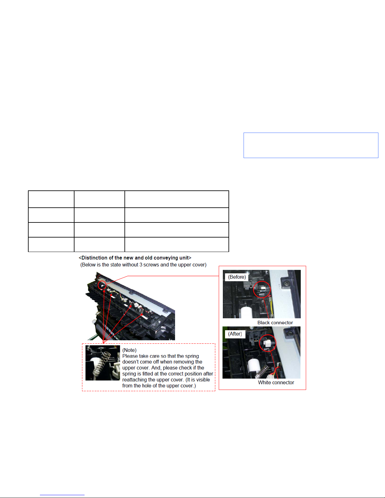
Check the firmware version. (Engine)
・8000i/6500i : 2LF_1000.002.005
・5500i/4500i/3500i : 2LF_1000.002.005
J05x8/J44xx(JAM during Duplex printing)
JAM during Duplex printing
a. If the version is older than the righthand, upgrade the firmware to the latest version.
b. After above “a” action, if JAM is still not solved, Replace the Conveying Unit.
Refer to the service bulletin No. 2LC-0036(B402),2LC-0083(C126) for the detail information.
Modified from the production machine of May, 2012 .
J05x8/J44xx(JAM duri ng Duplex pri nting)
Model Part No. Description
5500i/4500i 302LH94042 PARTS CONVEYING H UNIT(G) SP
3500i 302LL94012 PARTS CONVEYING L UNIT(G) SP
8000i/6500i 302LF94052 PARTS CONVEYING H UNIT(Z) SP
32
Page 33
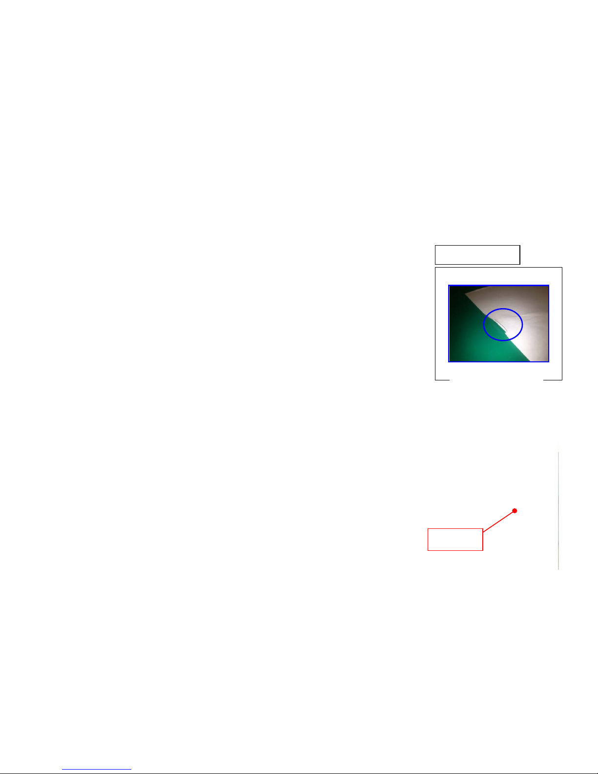
J0545 (Misfeeding JAM PF-770)
J0545 (no paper feeding JAM PF-770)
If J0545 occurs, take an action as referring to below procedure.
a. If JAM paper or printout paper is lik e a Fi g .1, replac e the Roller of the Primary
Feed. (Image sample 1)
b. Replace w ith 303NG9401 1 PARTS FEED UNIT SP if the producti on of
machine is before 2011 Dec.
c. At replacement, chec k or clear the count number of U901 Paper Feedi ng
Counter.
* The maintenance cycle for Primary Feed is 150K.*
Fig. 1 JAM Paper
For the detail, refer to the ser vice bulletin No. 3NG-004(C024)
Affected machines:After 2012 Jan production
Image sample 1
d. If the TRAY PAPER for paper loading w as assembled by slanting condit ion,
there is possibility of JAM0545 oc cur r i ng . In c ase of the pr obl em, check it
according to the next page "Inclination check and recov er ing pr ocedure of PF 770 TRAY PAPER" and corrected.
(There is a possibility that J0545/0555/1 305 /13 15 may occur.)
TRAY
PAPER
33
Page 34
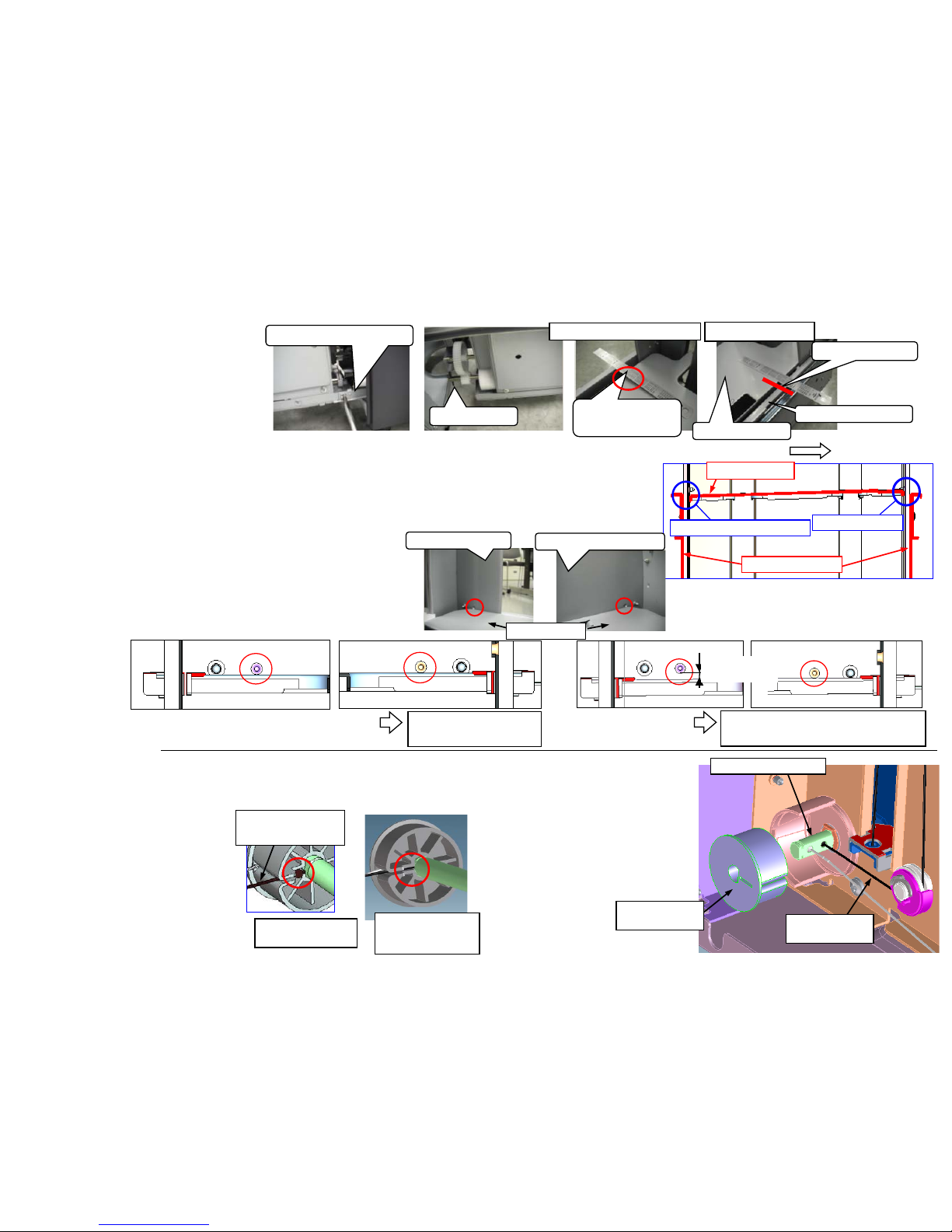
PF-770 Check & Recovery for Slating of TRAY PAPER
<Checking Procedure>
1. Remove the STOPPER DECK.
2. Check the right and left slanting
condition of the TRAY PAPER surface.
<Checking method>
Turn the SHAFT LIFT and adjust the top
part of STAY DECK SIDE becomes the
same flat surface level with the TRAY PAPER
at the FEED UNIT side.
In that height position, check that the TRAY PAPER surface of the opposite FEED UNIT side is lower than
the STAY DECK SIDE top part. In addition, the height of STAY DECK SIDE is the same height at the
FEED UNIT side and opposite FEED UNIT side.
1) If the opposite FEED UNIT side is lower than the FEED UNIT side・・・・OK
3. Check there is not slanting between the front and rear of the TRAY PAPER.
<Checking method>
Turn the SHAFT LIFT and when the top surface of the TRAY
PAPER is aligned with the convex part of FRAME DECK
REAR and FRAME F L,
1)Same flat height level at front and rear OK
2)If it has about 5mm difference height between front and rear NG
STOPPER DECK
Clearance
(about 5mm)
SHAFT LIFT
STAY DECK SIDE
Same flat level
FEED UNIT side
TRAY PAPER
Feeding direction
FEED UNIT side
STAY DECK SIDE
Opposite FEED UNIT side
TRAY PAPER
FRAME F L
FRAME DECK REAR
TRAY PAPER
Same height at front
/ rear OK
About 5mm
About 5mm difference between
front and rear height NG
<Recovery Procedure>
If above item 2 and 3 is NG, the following re-assembling is necessary.
At checking of above item 3, if the TRAY PAPER lower side is not
normal, it has a possibility that the
ball is out of position as shown in
the NG figure, re-assembly of the
wire is necessary.
In the case of NG above item 2, it
has a possibility that the ball is out
of position at both of front and rear,
re-assembly of an front and rear
wire is necessary.
OK : A ball terminal
goes into the hole
of shaft.
NG: A ball terminal
is out of shaft.
Black color
WIRE
* As shown in the right figure, make
it a ball terminal go into the hole of
SHAFT within PULLEY LIFT WIRE
DRUM at the time of re-assembly.
Be cautions especially at the time of
the assembly of a black wire.
SHAFT LIFT ASSY
WIRE LIFT L
black color
PULLEY LIFT
WIRE DRUM
Opposite FEED UNIT side
34
Page 35
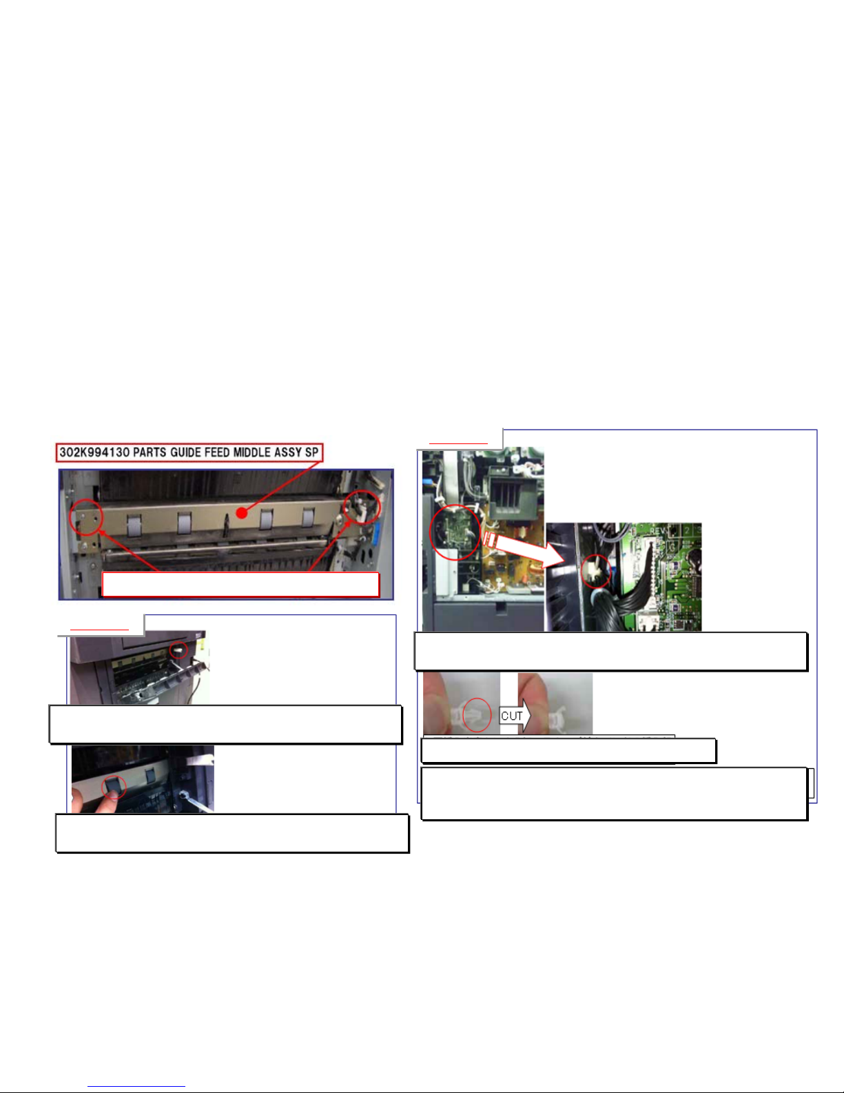
1. If J1313/J1314 occurs, take the measure as referring to the following.
a. Check whether installing 302K99 41 30 PARTS GUIDE FEED MIDDLE ASSY SP is proper.
The unit is not set properly, reinstall it.
b. Check whether 302K994430 PARTS ROLLER FEED LOW SP is rotating without power on the clutch.
* refer to the procedure-1
If the clutch is rotating, change the clutch cable wi r ing treatment. * refer to the procedure-2
c. If JAM is not solved after changing the clutch c abl e wiring, replace the 302K99 41 30 PARTS GUIDE FEED MIDDLE
ASSY SP unit.
J1313/J1314
c. Push in the wires inside of the machine through the hole on the metal
plate where the wire fastener was fitted. *Then, take care the connector at
the feed drive unit side not to be loose.
b. Cut the snap-fit part not to refit after the measures
a. Remove the snap-fit wire fastener from the side plate that is fitted to the
machine frame in the feed drive unit.
Procedure-2
Procedure-1
Check this installation part whether properly fitted.
1. While opening the feed cover, turn on this SW
2. Execute U032 Check Clutch Operation to select “MOTOR”.
3. Check this roller is not rotated. *If rotating, the clutch is on without
operating.
35
Page 36
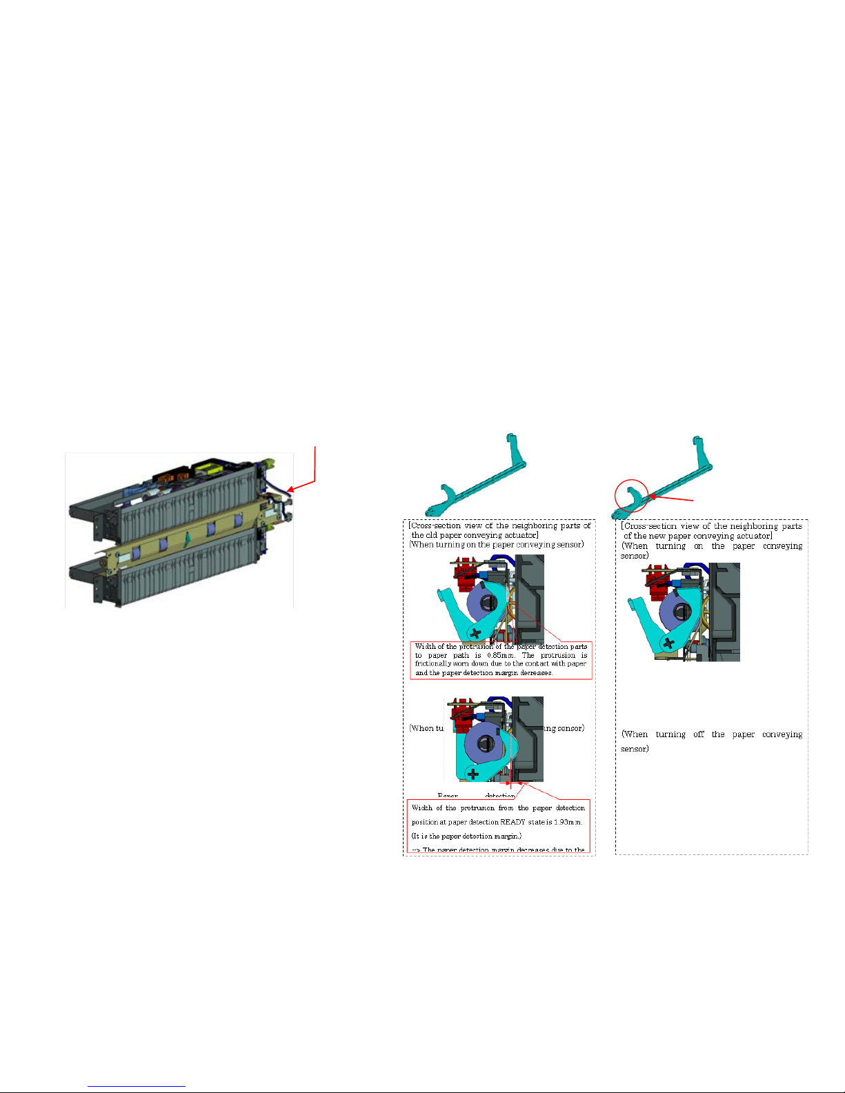
J150X/J1904
【Phenomenon】
The paper conveying actuator is scraped for a long usage, J1904 and J150X occurs due to sensor detection failure
depending on the paper.
【How to respond】
Replace the actuator (ACTUATOR FEED LOW 302N706500) when the problem occurred.
【Service Bulletin】
2LC-0123(D148)
(500-sheet cassette feed section for the main machine)
Paper conveying sensor (PCS/PFPCS2)
<Paper conveying actuator>
Changed the shape of the
paper detection parts
(Before) (After)
36
Page 37

J1512
【Phenomenon】
The cassette 4 paper may not stop before the feed sensor (middle sensor at vertical conveying)
and the sensor may be turned on while the cassette 2 paper stays at the registration for duplex
feed.
【Change】
Paper waiting position for the next feeding paper after feeding paper from the cassette 2 is changed.
(About 50mm before the current position)
Upgrade to the latest F/W. (Upgrade Pack Ver. V5.00 or above)
【Service Bulletin】
2LC-0116(D089)
37
Page 38
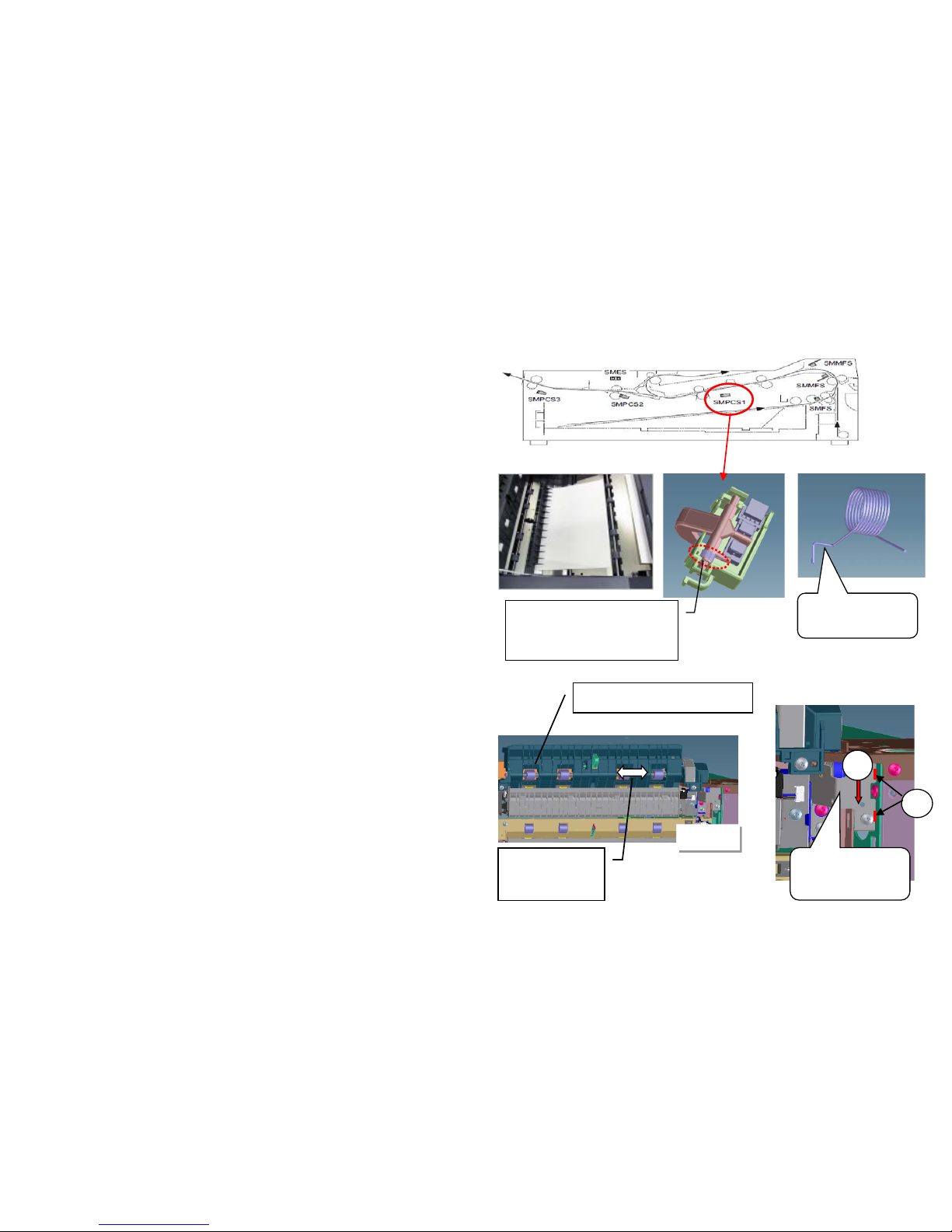
PF-780
If J341X occurs, take the measure as referring to
the following.
If the ACTUEATOR of SMPCS1 is slow to return to the
home position, it occurs.
a. Replace the actuator spring w ith 303NL06510
SPRING ACTUEATOR PI
b. If PF-730 for the 6th/7th cassette is installed and after
replacing the above spring, JAM still occurs , c heck
whether the 303NF06100 ROLLER CONVEYING VF is
moving the thrust dir ecti on.
If the movement of unit is heavy, re-install the 303NJ31040
PLATE DECK JOINT located at right side while making the
edge of (1) contacting with FRAME REAR, shift lower
direction of arrow (2).
Shape of
modified spring
Shift it
smoothly this
thrust direction
ROLLER CONVEYING VF
1
2
303NJ31040
PLATE DECK
JOINT
Refer to service bulletin No. 3NJ-0001(B354)for the detail
Affected machines:After 2011 Oct . production
Refer to service bulletin No. 3NL-0001(C059)for the detail
Affected machines:After 2012 Feb production
J341X
Replace with
303NL06510
SPRING ACTUATOR PI
PF-730
38
Page 39
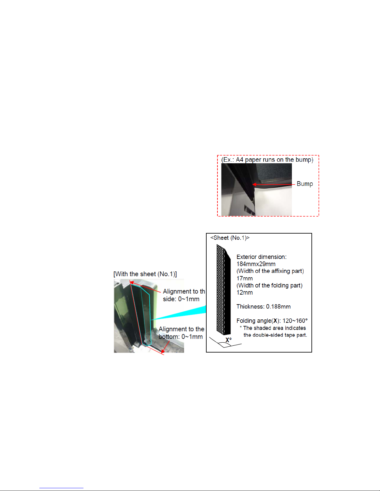
J4103/4104
Check whether a cor ner of A4 paper runs on the bump with a
step of 1 1x8. 5 siz e.
When paper runs on, set paper correctly. Please adhesive the
regulation sheet: PARTS SHEET STOPPER A4 SP(303NF94170)
as needed.
*If paper seriously runs on, C1100/11 10 may occur.
1.When J4103/4104 oc cur at t he ti me of A4 size paper feed from
the large-capacity deck 3 or 4, please take the following measure.
39
Page 40
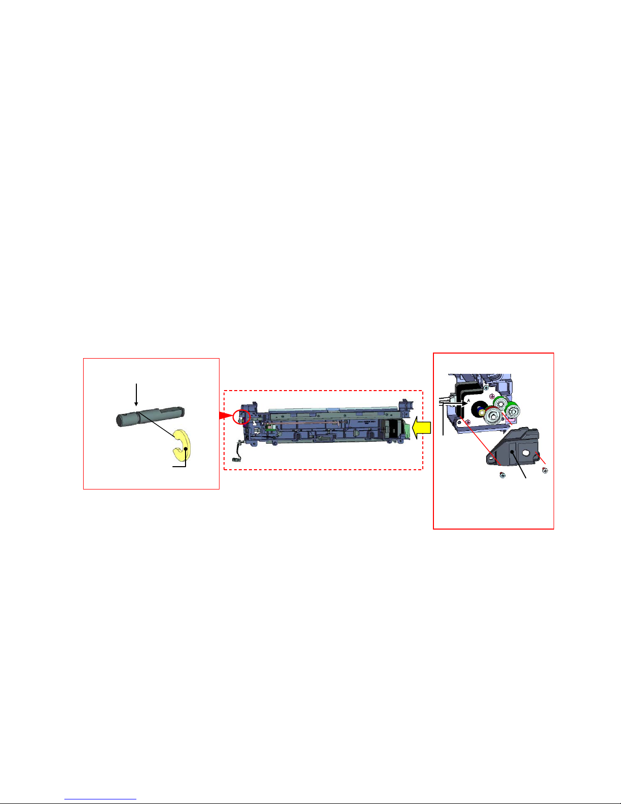
Abnormal Sound/J42XX/J40XX(Add Intermediate Mot or Cover)
【Phenomenon】
The abnormal noise may be heard or the Jam (J42XX/J40XX) may occur if the gear of the middle
roller drive motor is worn with toner spillage.
Model:TASAalfa8000i/6500i
【How to respond】
The cover (302N724020:COVER MOTOR MIDDLE) is added to prevent the gear wear.
【Service Bulletin】
2K9-0040(D153)
For 6500i/8000i
PARTS GUIDE FEED REGIST ASSY SP
X
<Viewed from X>
Groove width of the shaft
(1.3±1mm -> 0.8±0.1mm)
Cut washer
(t=1.0 -> t=0.5)
Added Cover
* Fixed together with the
metal plate (Y) with the
screw
Metal
plate (Y)
40
Page 41
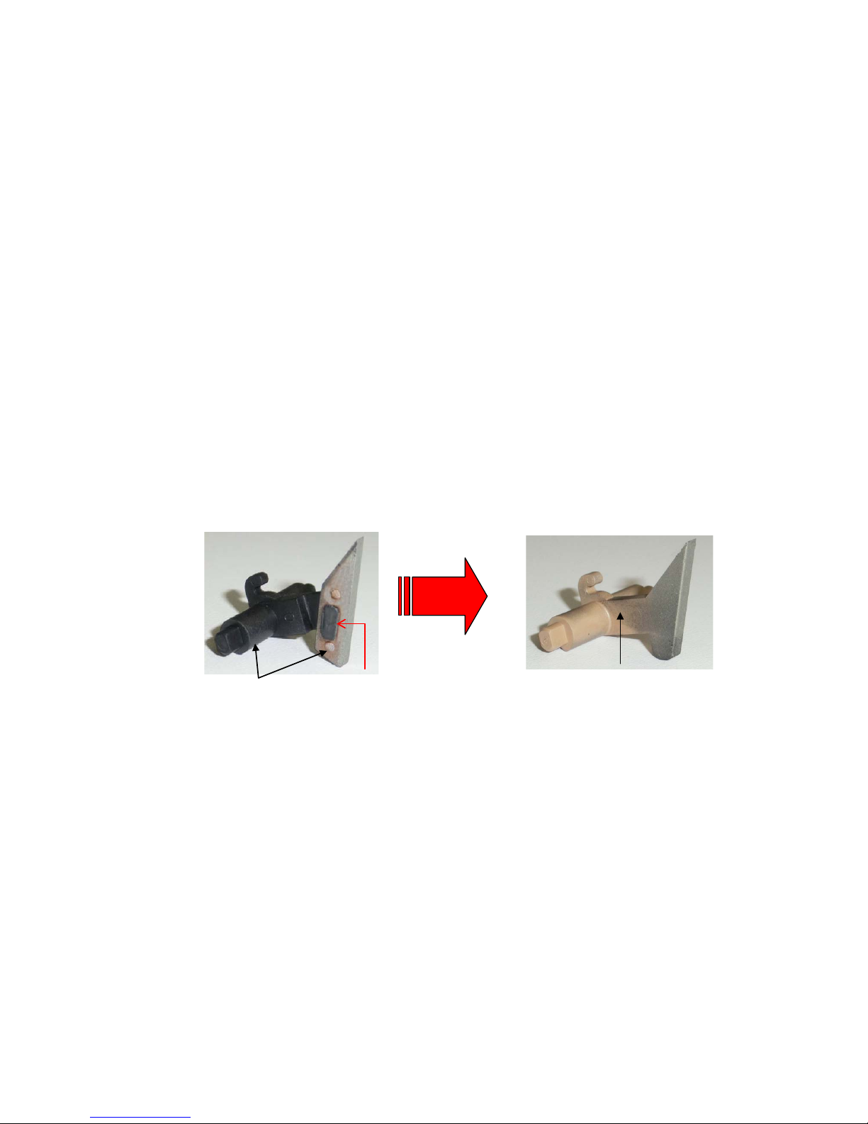
J42XX/ The separation cla w cracks or comes off
J42xx occurred frequently, replace w ith the new claws or new parts when the separation claw cracks or
comes off.
Single Item :302FT20120 SEP ARATOR ASSY
Assembly :302LH94370 P ARTS SEP ARATOR ASSY SP
If the claw is broken in half, please change to the new claw (claw that is integrated).
【Service Bulletin】:2LH-0016 (D159)
For 3500i/4500i/5500i
(Before)
(After)
The claw and holder
are joined
Unifying the claw and hold
prevents the crack at the
joint part
The claw may crack or come
off from the joint part
41
Page 42
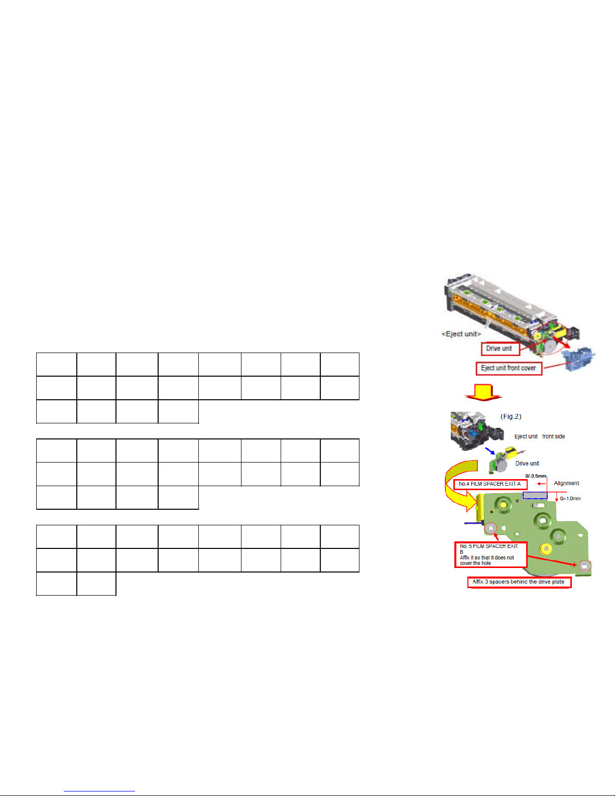
If J421X/J460X/J470X occurs.
1. In case of JAM at the shift guide of the exit unit part, take the following measure.
a. Increase the clearance between the housing and the shi ft guide, attach the foll ow ing s pacers
(No.1: 3pcs in one set ) on the driving plate.
*302LC94660(PARTS FILM SPACER EXIT SET SP) 1SET
*Refer to the service bulletin: 2LC-0037(B405)
■Affected machine’s serial number
J421X / J460X / J470X (1/2)
5500i
KDJ ▲KDA KDA(AK) ▲CPY CS(AK) ▲KDA GSA ▲KDBR ▲KDA 220V
1102LH9JP0 1102LH2US0 1102LH2US2 1102LH2CS0 1102LH2CS1 1102LH2US1 1102LH2BR0 1102LH4US0
N3W1Y00307 N3X1Z02903 NWN1Y00001 NHJ1Z00472 NWM1Y00001 NLR2100106 NJC1Z00026 NHZ1Z00008
KDE ▲UTAX ▲OLIVETTI KDAU KDCN ▲KDKR KDTW ▲KDHK
1102LH3NL0 1102LH3UT0 1102LH3LV0 1102LH3AS0 1102LH3KS0 1102LH3KR0 1102LHTTW0 1102LH3HK0
N3Y1Y02250 N411Z00865 NK31Z00221 NextPdct NKR1Z00101 NMS1Z00106 NJS1Y00030 NJ61Z00046
KDID ▲KDSG KDTH Philcopy
1102LH3ND0 1102LH3SG0 1102LH3TH0 1102LH4PH0
NHZ1Y00006 NJ91Z00198 NJ31Y00176 NextPdct
4500i
▲KDJ KDA KDA(AK) ▲CPY CS(AK) KDA GSA KDBR ▲KDA 220V
1102LJ9JP0 1102LJ2US0 1102LJ2US2 1102LJ2CS0 1102LJ2CS1 1102LJ2US1 1102LJ2BR0 1102LJ4US0
N421Z00668 N431Y02336 NWQ1Y00001 NHK1Z00485 NWP1Y00001 NextPdct NJB1Z00040 NHR1Z00017
KDE ▲UTAX ▲OLIVETTI KDAU KDCN ▲KDKR ▲KDTW ▲KDHK
1102LJ3NL0 1102LJ3UT0 1102LJ3LV0 1102LJ3AS0 1102LJ3KS0 1102LJ3KR0 1102LJTTW0 1102LJ3HK0
N441Y02505 N461Z01265 NK41Z00321 NextPdct NKS1Z00101 NMT1Z00091 NJT1Z00093 NJ51Z00128
▲KDID ▲KDSG ▲KDTH Philcopy
1102LJ3ND0 1102LJ3SG0 1102LJ3TH0 1102LJ4PH0
NHY1Z00015 NJ81Z00373 NJ21Z00106 NextPdct
3500i
KDJ KDA ▲CPY ▲KDA GSA KDBR KDA 220V KDE UTAX
1102LL9JP0 1102LL2US0 1102LL2CS0 1102LL2US1 1102LL2BR0 1102LL4US0 1102LL3NL0 1102LL3UT0
N471Y00539 N481Y04077 NHL1Z00712 NLT2100181 NJA1Y00051 NextPdct N491Y02575 N4B1Y02215
▲OLIVETTI KDAU ▲KDCN ▲KDKR ▲KDTW KDHK ▲KDID ▲KDSG
1102LL3LV0 1102LL3AS0 1102LL3KS0 1102LL3KR0 1102LLTTW0 1102LL3HK0 1102LL3ND0 1102LL3SG0
NK51Z00381 NextPdct NKU2100301 NMU1Y00732 NJU1Z00024 NextPdct NHX1Z00022 NJ71Z00067
KDTH Philcopy
1102LL3TH0 1102LL4PH0
NextPdct NextPdct
42
Page 43
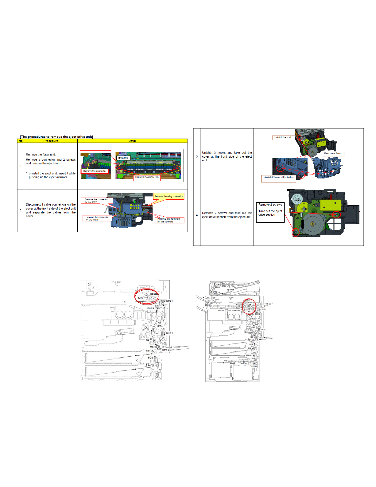
■Removal procedure for the exit drive unit
3500i/4500i/5500i/6500i/8000i
b. When the entire paper is not damaged at JAM.
Since there is a possibility of incorrect detection of the sensor, please replace the sensor in the inside of the
eject unit, or the eject unit.
* Sensor:7NXGP1A73LCH01(SENSOR OPT.) Eject unit:302LH94271(PARTS EXIT UNIT B SP)
* Measurement time : April 2012 (after March 2012 production lot, the sensor selection is executed.)
J421X / J460X / J470X (2/2)
43
Page 44
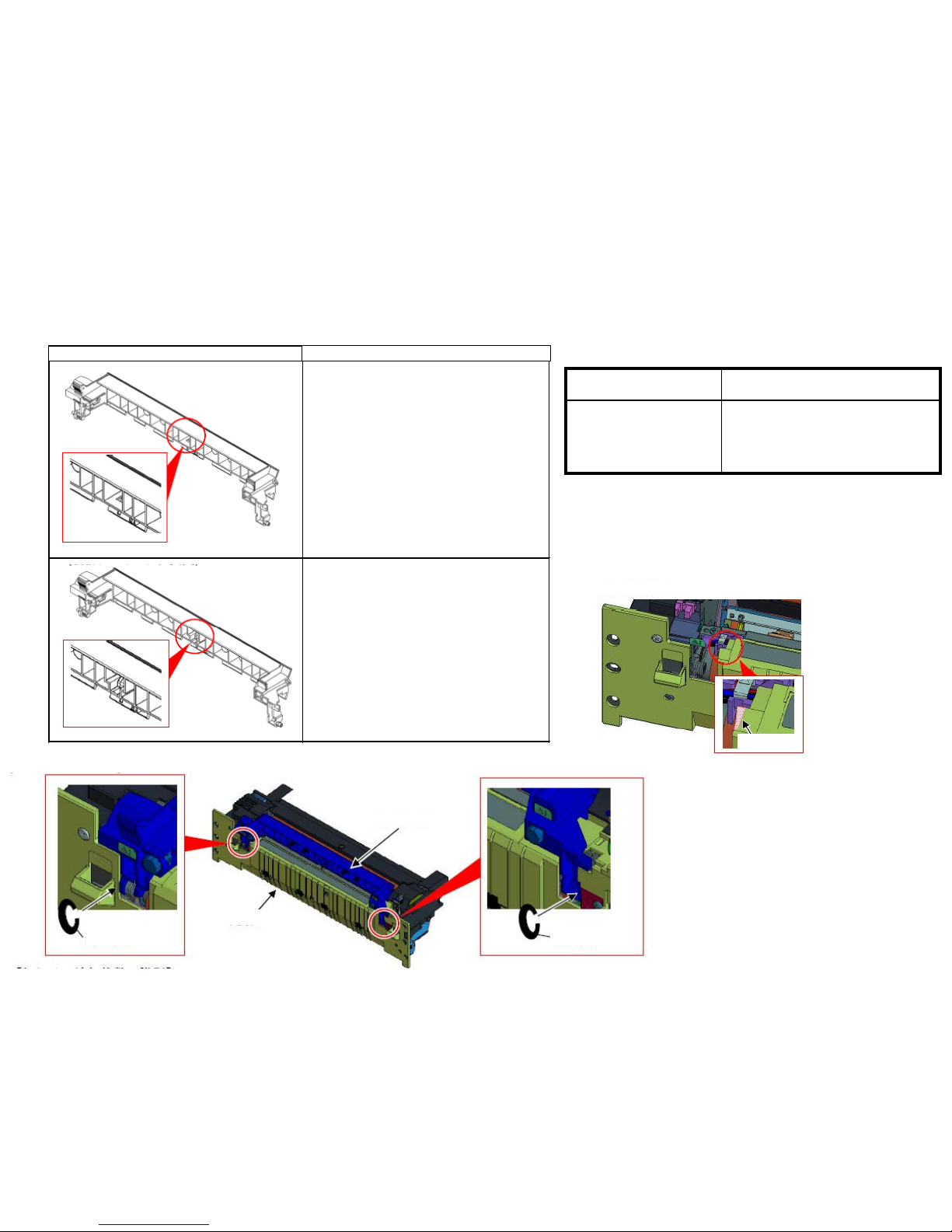
J421X(Fuser exit sensor stay jam)
【Service Bulletin】
2K9-0021(C155)
【Permanent support】
Exit guide rib shape change + fixing cover ribs added
Sept 2013 - production: corresponding time
Item Number Item Name
302K994C40 PARTS CUT-WASHER 6 SET SP
*Set bundling 2 pcs of the cut
washer
In the case of J421X occurs, check the fuser guide shape of the fixing, it will be required the following.
排出ガイド形状 対応方法
カットワッシャーを以下支点部に追加して下さい。
・機械前側支点部:1枚
・機械後側支点部:2枚
カットワッシャーを以下支点部に追加して下さい。
・機械後側支点部:2枚
For 6500i/8000i
Shape of Fuser exit guide
How to respond
Added 2 cut washers to the fulcrum of the
fuser exit guide.
・Machine front fulcrum:1pc
・Machine back fulcrum:2pc s
Please add to the fulcrum below the cut
washer.
・Machine back fulcrum:2pc s
New Fuser Cover
Cut washer mounting position
Cut washer
Exit guide
Cut washer
Fuser cover
Add rib
44
Page 45
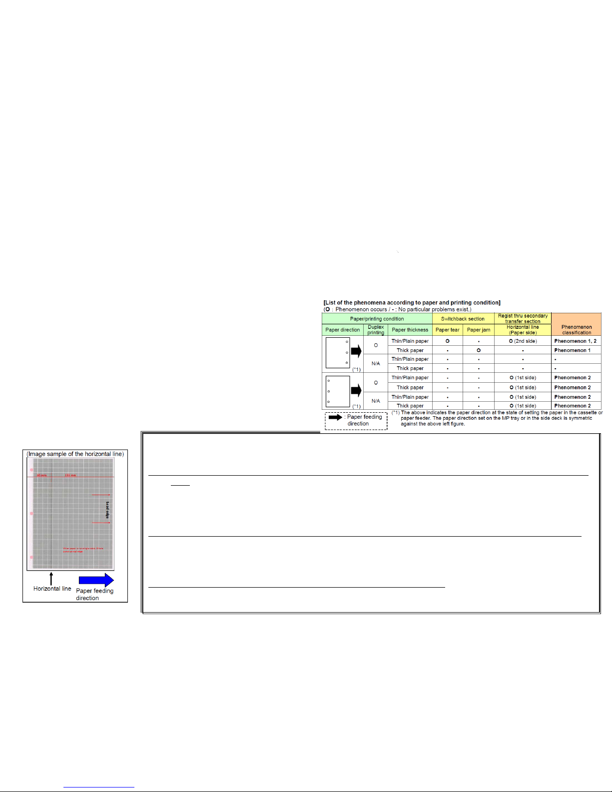
Paper tear, J430X/431X/440X/471X, Horizontal line at 60mm
from bottom edge
(Phenomenon1)
If the leading edge of the actuator switching the switchback sensor is hooked with the center hole of 3-hole pre-punched
paper when the paper is turned over with the duplex printing, the paper may be torn or the paper jam
(J430X/431X/440X/471X) may occur depending on paper thickness.
(If the paper is torn, the following phenomenon 2 may occur at the same time.)
a Replace the EXIT UNIT (PARTS EXIT UNIT B SP :302LH94272)
3500i/4500i/5500i:PARTS EXIT UNIT B SP (302LH94272)
6500i/8000i :PARTS EXIT UNIT A SP(302K994662)
(Phenomenon2)
the horizontal line on the image of the paper rear side.
a Check the most updated firmware version and version up the firmware.
Check the Firmware version and version up to above FW PACK V4.00.
1. During usage of a pre-punch paper with 3 holes, if paper tear/JAM and horizontal line at 60mm from bottom edge occur, please take the following
measure.
[Restriction when using 3-hole pre-punched pap er]
Please kee p and perform the following restrictions when using 3-hole pre-punched paper even if performing
the corrective measures.
1.The length of the punched hole in the paper feeding directio n o n 3-hole pr e-punch ed paper must be 8mm or
less.
If the punching hole is longer than 8mm in lengthwise, the leading edge of the actuator switching the
switchback sens o r falls down the center hole o f th e paper when turning over the paper in duplex
printing and as the result, the punched hole may be torn or the paper jam may occur.
(Phenomenon 1: Tear/jam of the paper at the switchback section)
2.The distance between the hole of 3-hole pre-punched paper and the paper rear end must be 15mm or less.
If the punched hole is farther than 15mm from the paper rear end, the interval to the next fed paper
becomes short and then the regist drive stops though the paper doesn’t pass through yet. As the result,
the horizontal line a p p ears on the image. (Phenomenon 2: Horizontal line on the image of the paper rear
side.)
3.Don’t eject 3-hole pre-punched paper to the JS-731 (right job separator).
The JAM 470x/471x may occur due to chattering of the fuser eject sensor if trying to eject 3-hole pre-
punched paper to the JS-731.
45
Page 46
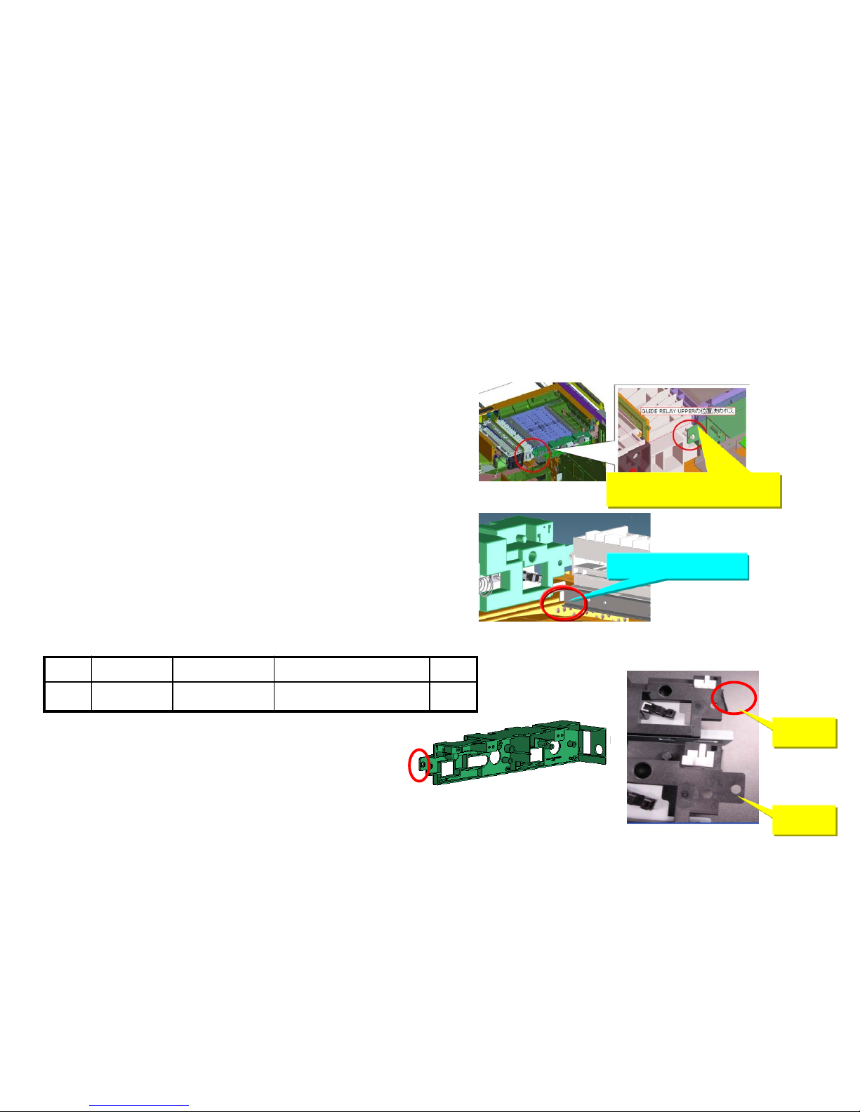
1. Check whether the positioning of bridge conveying-in unit is
inserted into the positioning hole of the drive unit.
If it is not inserted into the positioning hole.
a.While being careful not to contact with the tray in following fig, insert the
positioning boss of AK conveying-in unit into the positioning hole of the
drive unit.
Positioning with the drive unit
Contact part of the tray
If J49XX/J50XX/J51XX/J600X occurs, check the following item 1 to 7.
2. Check whether the positioning hole of the bridge drive un it is damaged.
If it is damaged, replace the AK drive unit (following item number.)
Broken
Normal
No. Old New item number Parts name Q’ty
1
303NB94200 PARTS DRIVE UNIT SP
1
J49XX / J50XX / J51XX / J600X (1/9)
46
Page 47
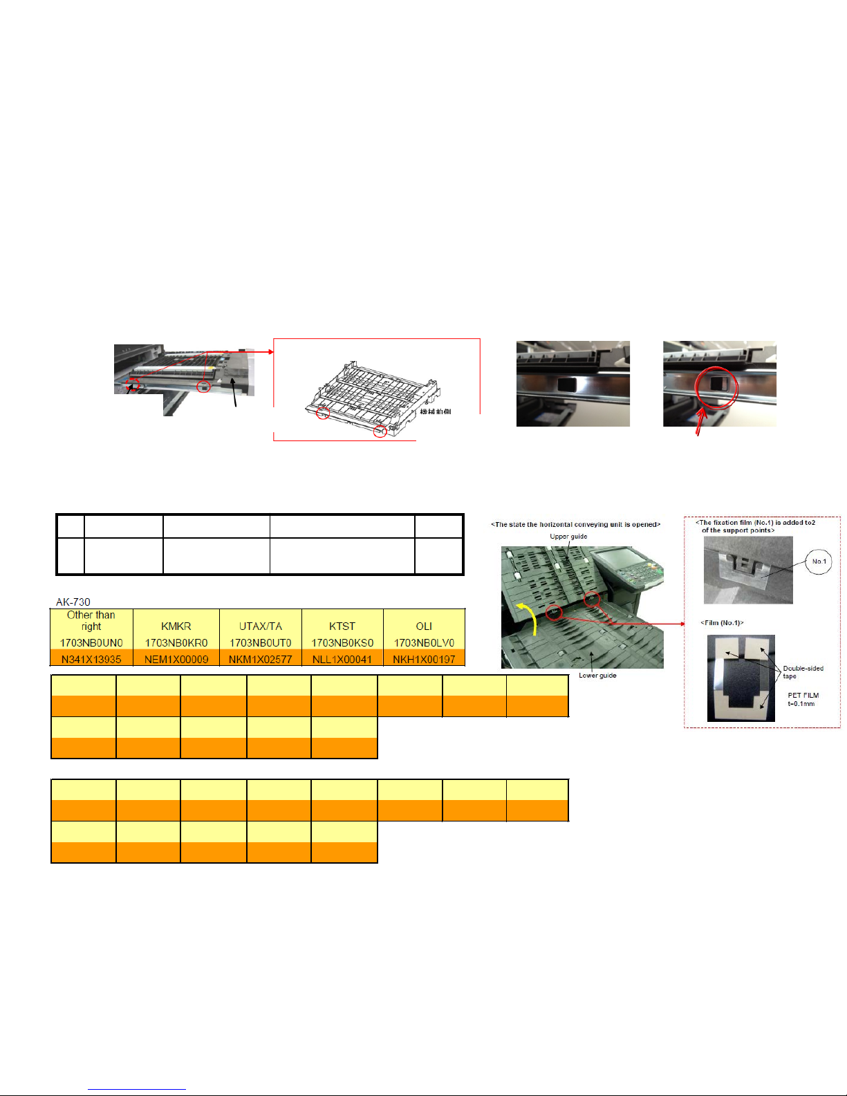
3. Check the positioning cutout part (red circle at below fig.) at the left slider section of the bridge conveying unit is fitted to red round
mark on the slider section.
■Affected machine’s serial number is below
№ Old New Parts No Parts name Q’ty
1 302LF28770
2LF28770
SHEET HINGE
STOPPER
2
(Right) (Wrong)
Clearance
4. Check whether the leverage of upper conveying guide on the bridge conveying unit is not detached.
if it is detached, add the below parts as referring the procedure mentioning next page.
【Service Bulletin】2LF-0004(B355)
Refer to the service bulletin:2LC-0034(B395)
[Conveying unit fixing]
AK eject unit
slide
rail
AK carry-in unit
Machine front
side
<AK conveying unit>
J49XX / J50XX / J51XX / J600X (2/9)
8000i
KDA CPY KDA GSA KDBR KDA 220V I KDE UTAX OLIVETTI
1102LF2US0 1102LF2CS0 1102LF2US1 1102LF2BR0 1102LF4US0 1102LF3NL0 1102LF3UT0 1102LF3LV0
From nex t From next
production produc tion
KDAU KDCN KDKR KDTW KDSG
1102LF3AS0 1102LF3KS0 1102LF3KR0 1102LFTTW0 1102LF3SG0
From nex t
production
6500i
KDA CPY KDA GSA KDBR KDA 220V I KDE UTAX OLIVETTI
1102LG2US0 1102LG2CS0 1102LG2US1 1102LG2BR0 1102LG4US0 1102LG3NL0 1102LG3UT0 1102LG3LV0
From nex t From next
production
production
KDAU KDCN KDKR KDTW KDSG
1102LG3AS0 1102LG3KS0 1102LG3KR0 1102LGTTW0 1102LG3SG0
From nex t (-->)
production NJR2100003
N4U1Y00818
NHG1Y00207
NHH1Y00006
N4V1Y00423
N4X1Y00183
NK21Y00021
NKQ1Y00021
NMR1Y00009
NJL1Y00084
N4P1X00646
NHE1X00173
NHF1X00011
N4Q1X00421
N4S1X00067
NK11X00024
NKP1X00011
NMQ1X00013
(-->)
NJQ2100002
NJK1X00073
47
Page 48
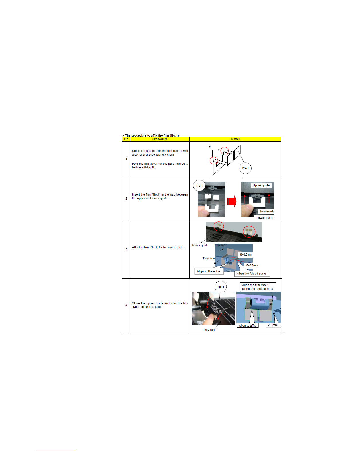
■The film attached procedure
J49XX / J50XX / J51XX / J600X (3/9)
48
Page 49
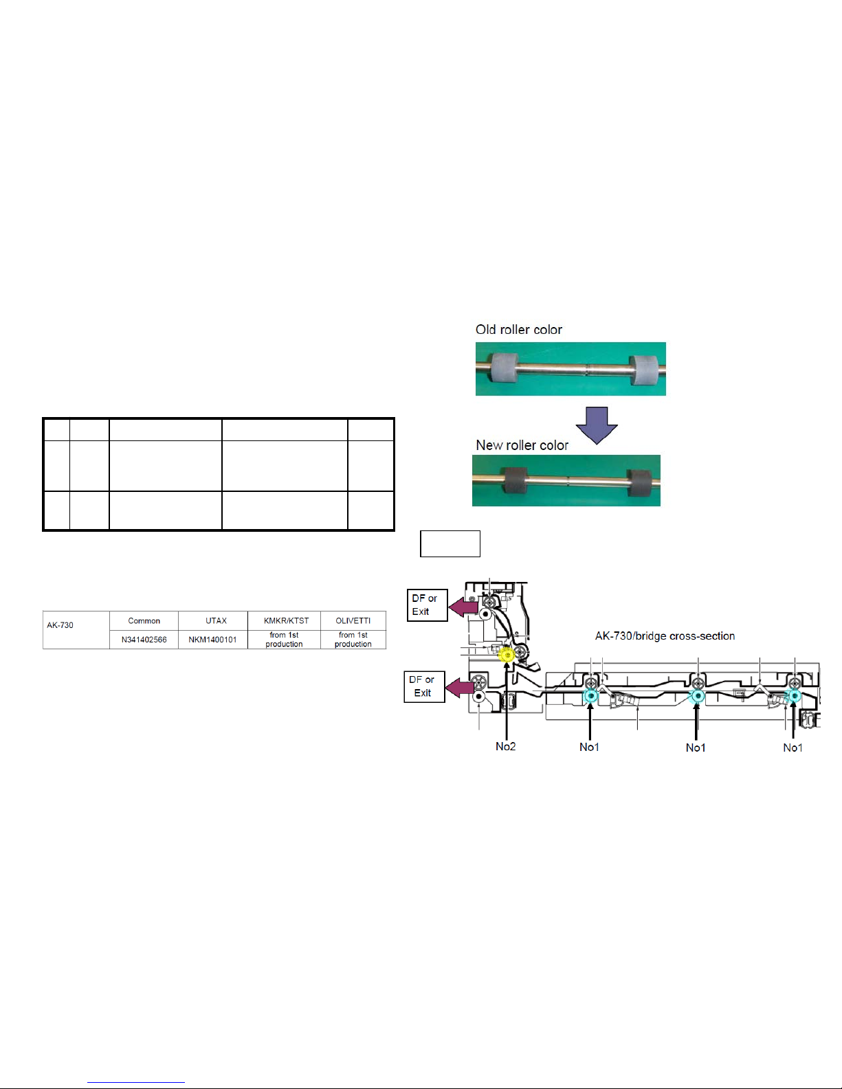
5. Check the material of roller at the bridge conveying-in unit
(Fig.1)
If it is old type shown in right fig, replace the roller.
Fig 1
№ Old New Item Number Parts Name Q’ty
1 302LF94010
2LF94010
PARTS ROLLER
RELAY MIDDLE SP
3
2 302LF94030
2LF94030
PARTS ROLLER
RELAY EXIT SP
1
■ Affected machine’s serial number is below
【Service bulletin】3NB-0001(B235)
J49XX / J50XX / J51XX / J600X (4/9)
49
Page 50
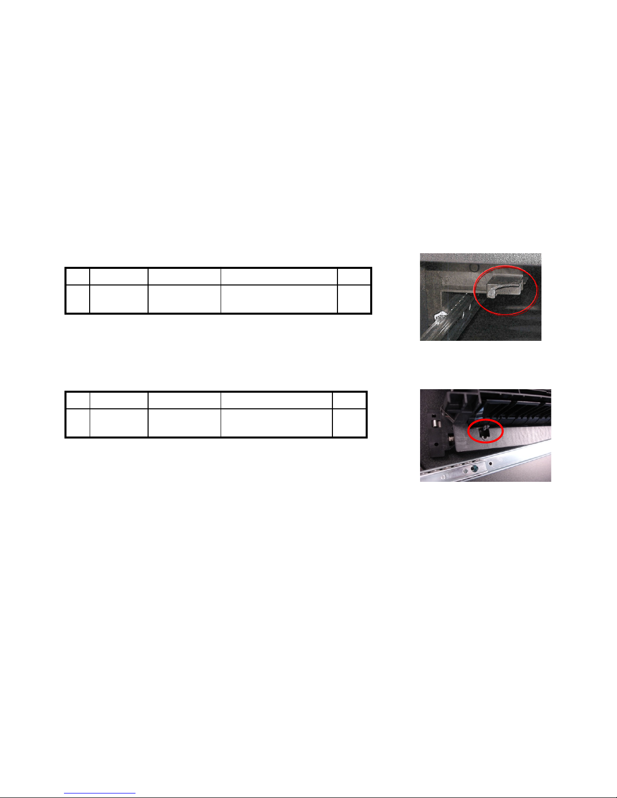
7. Check whether the screw fixed boss, positioning boss of the Rail installing section at the bridge
relay exit unit is broken. If it is broken, replace the relay exit unit.
No. Old New Parts No Parts name Q’ty
1 303NB94174
3NB94174
PARTS RELAY EXIT SP 1
6. Check there is any breakage at the hook hang part of the bridge relay exit unit. (Right fig.)
If it is broken, replace the relay exit unit.
No. Old New Parts No Parts name Q’ty
1
303NB94174
3NB94174
PARTS RELAY EXIT SP
1
【Service bulletin】2LC-0034(B395)
J49XX / J50XX / J51XX / J600X (5/9)
50
Page 51
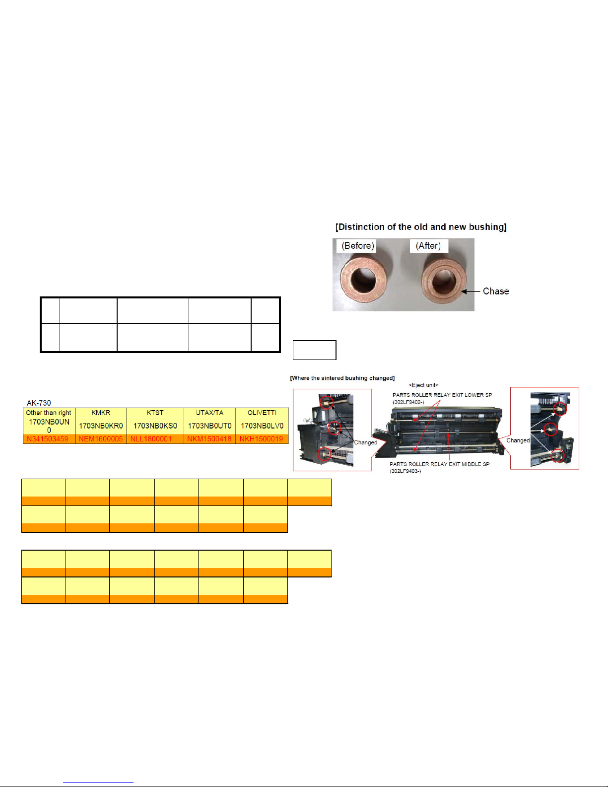
8. Check the bushin g o f th e Bridge Exit Unit (Fig.1)
If it is old type shown in right fig, replace the bushing according
to the replacement procedure (refer to the next page).
Fig 1
№ Old New Item
Number
Parts Name Q’ty
1 302K324450
2K324450
BUSH 6 6
■ Affected machine’s serial number is below
【Service bulletin】2LC-0059(C038)
J49XX / J50XX / J51XX / J600X (6/9)
8000i
KDA CPY KDA GSA KDBR KDA 220VI KDE UTAX
1102LF2US0 1102LF2CS0 1102LF2US1 1102LF2BR0 1102LF4US0 1102LF3NL0 1102LF3UT0
N4P1600107 NHE1600041
1st production NJE1600001 NHF1700001 N4Q1500041 N4S1500001
OLIVETTI KDAUS KDCN KDKR KDTW KDSG
1102LF3LV0 1102LF3AS0 1102LF3KS0 1102LF3KR0 1102LFTTW0 1102LF3SG0
NK11600001 N4R1600012 NKP1800001
NMQ1700001 NJQ1900001 NJK1500001
6500i
KDA CPY KDA GSA KDBR KDA 220VI KDE UTAX
1102LG2US0 1102LG2CS0 1102LG2US1 1102LG2BR0 1102LG4US0 1102LG3NL0 1102LG3UT0
N4U1500102 NHG1500021 1st production
NJD1500001 NHH1700001 N4V1500021 N4X1500001
OLIVETTI KDAU KDCN KDKR KDTW KDSG
1102LG3LV0 1102LG3AS0 1102LG3KS0 1102LG3KR0 1102LGTTW0 1102LG3SG0
NK21600001 N4W1500001 NKQ1800001 NMR1700001 NJR1900001 NJL1500001
51
Page 52
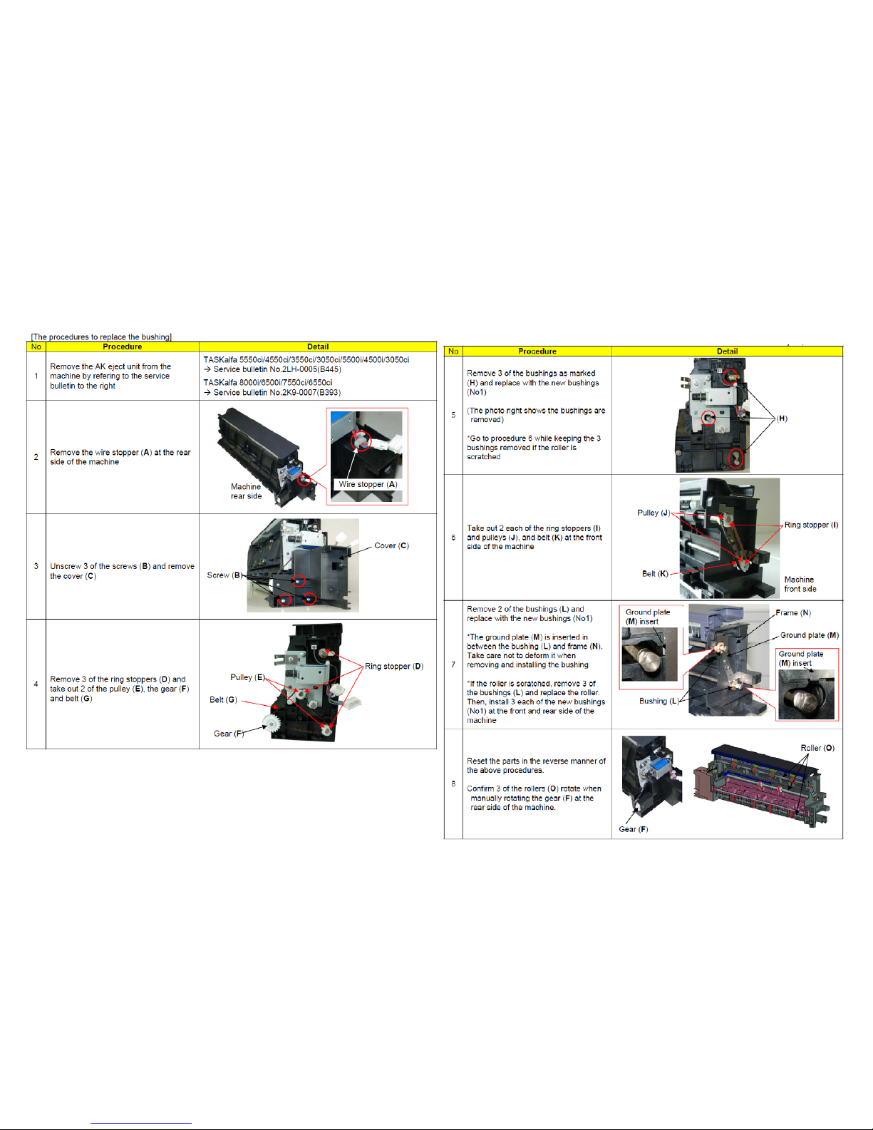
■Replacement procedure for the bushing
J49XX / J50XX / J51XX / J600X (7/9)
52
Page 53
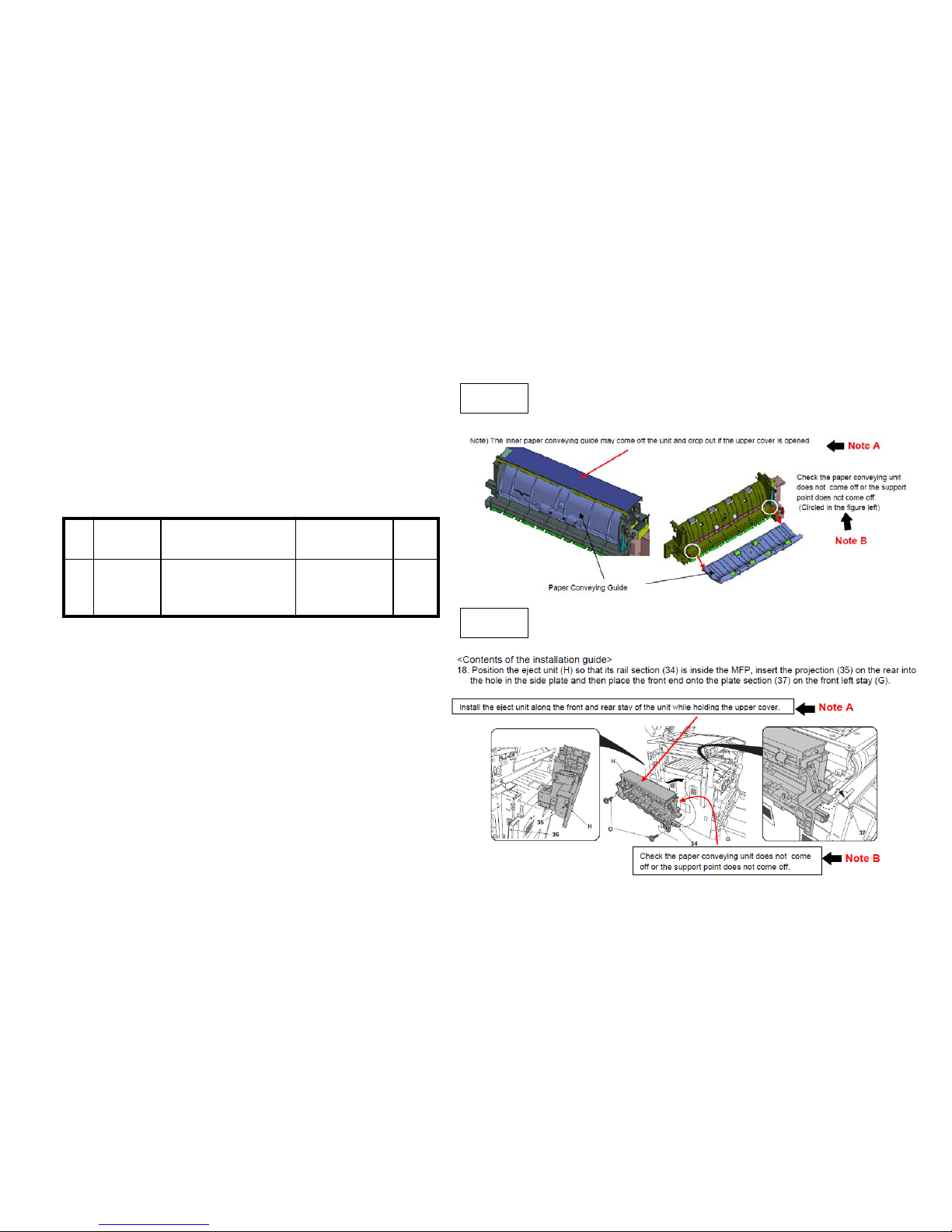
9. Check whether the check whether the paper conveying
guide fulcrum for the bridge exit unit has separated or n o t.
(fig.1).
If it is separated, install the following parts (Fig 2)
a. install it to the front and rear stay while holding the upper cover
of exit unit.
b. Check whether the paper conveying guide does not come off and
the fulcrum parts is not separated.
Fig 1
№ Old New Parts Items Parts Name Q’ty
1 302LF28240
2LF28240
GUIDE
RELAY EXIT
RIGHT
1
【Service Bulletin】2LC-0015(B221)
Fig 2
J49XX / J50XX / J51XX / J600X (8/9)
53
Page 54
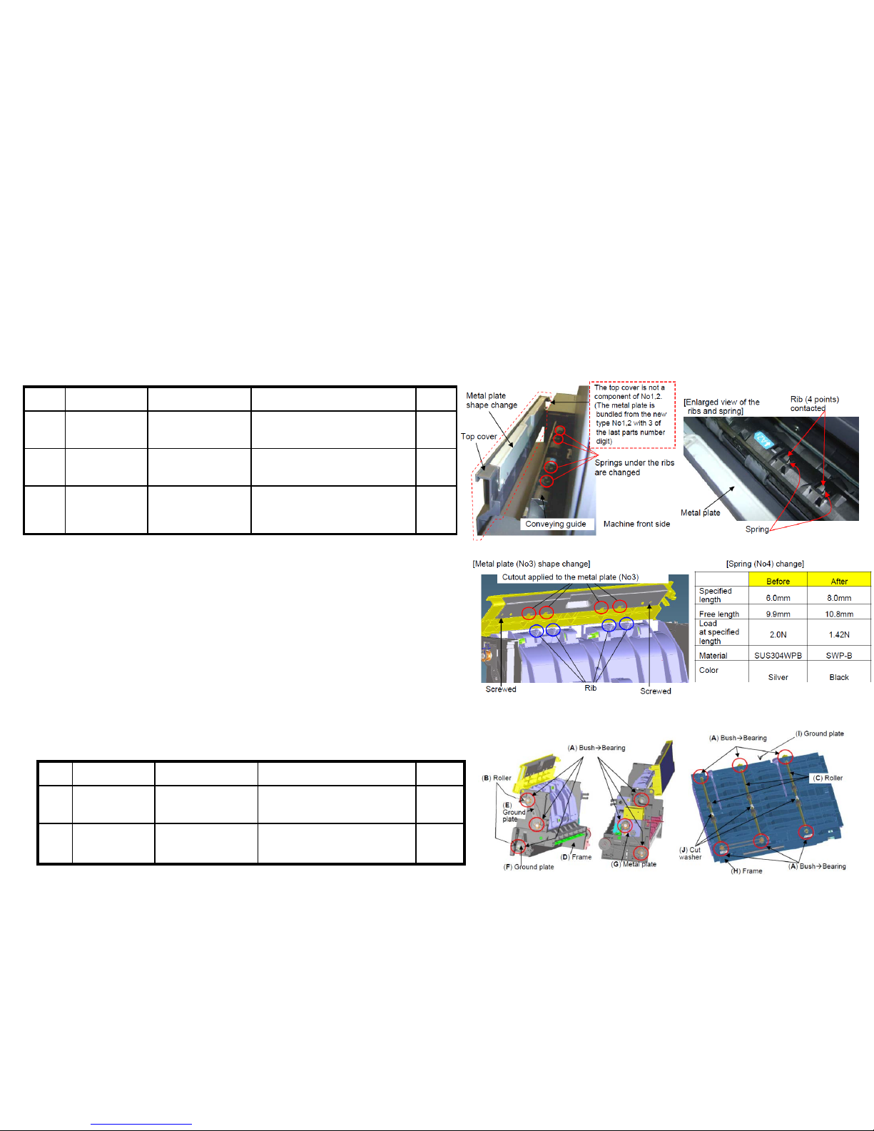
10.Check whether the rib (blue color round mark on the right fig) of the conveying guide of the bridge exit unit is broken
or not.
In case of breakage, replace the below part No.1 to 3 as referring to the service bulletin “2LC-0068(C076)
11. After performing above items 1 to 10, JAM still occurs, replace the bridge
conveying unit, bridge relay exit unit.
*Bush ⇒ Bearing
No. Old New Parts No Parts name Q’ty
1
303NB94241
3NB94241
PARTS GUIDE UPPER
UNIT SP
1
2
303NB94174
3NB94174
PARTS RELAY EXIT SP
1
No. Old New Parts No Parts name Q’ty
1 303NB94174
3NB94174
PARTS RELAY EXIT SP 1
2 302LF28621
2LF28621
+PLATE REINFORCEMENT
EXIT
1
3 302LF28840
2LF28840
+SPRING-COMPRESSION
RELAY EXIT
4
【Service bulletin】2LC-0068(C076)
J49XX/J50XX/J51XX/J600X (9/9)
【Service bulletin】2LC-0059(C038)
54
Page 55
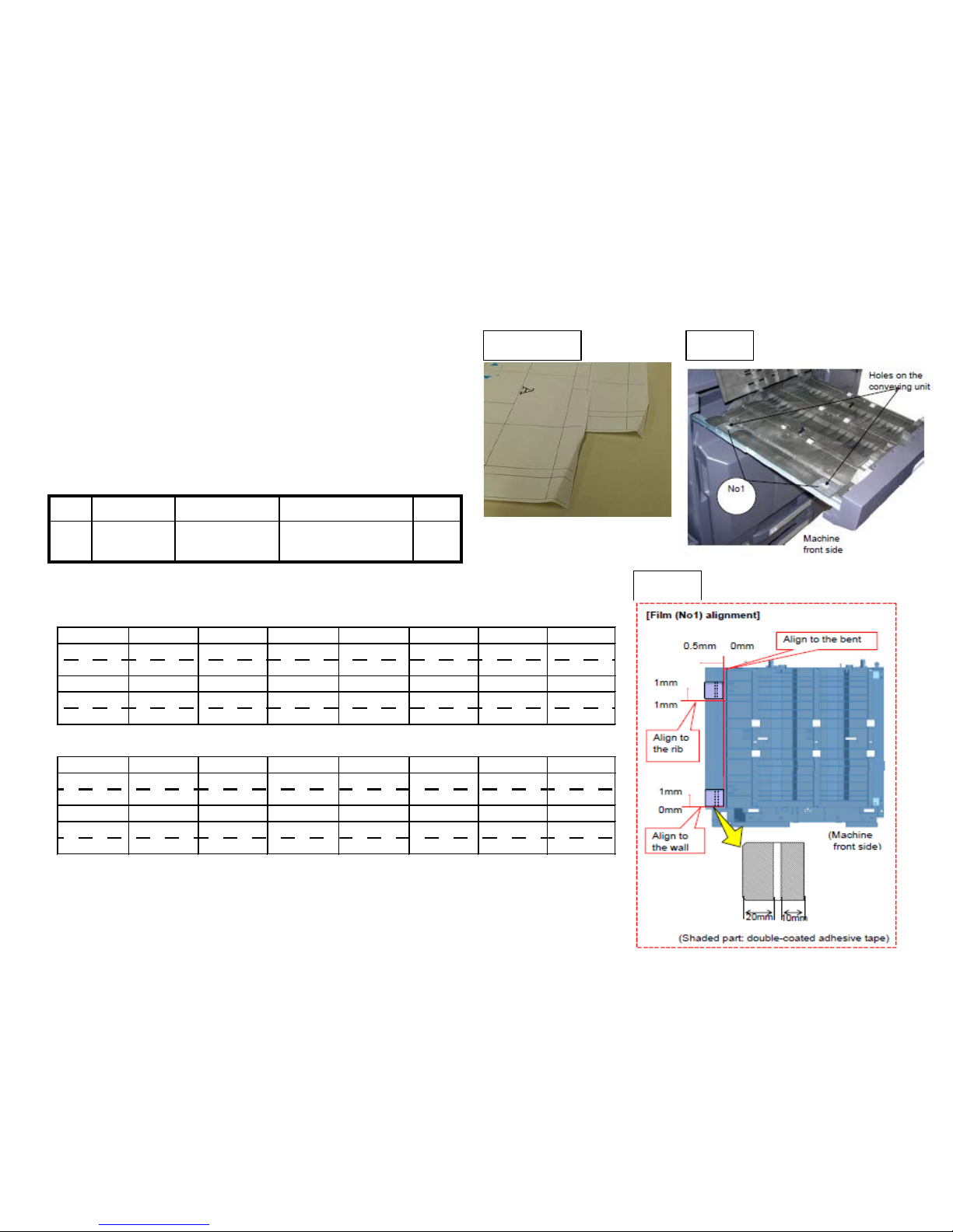
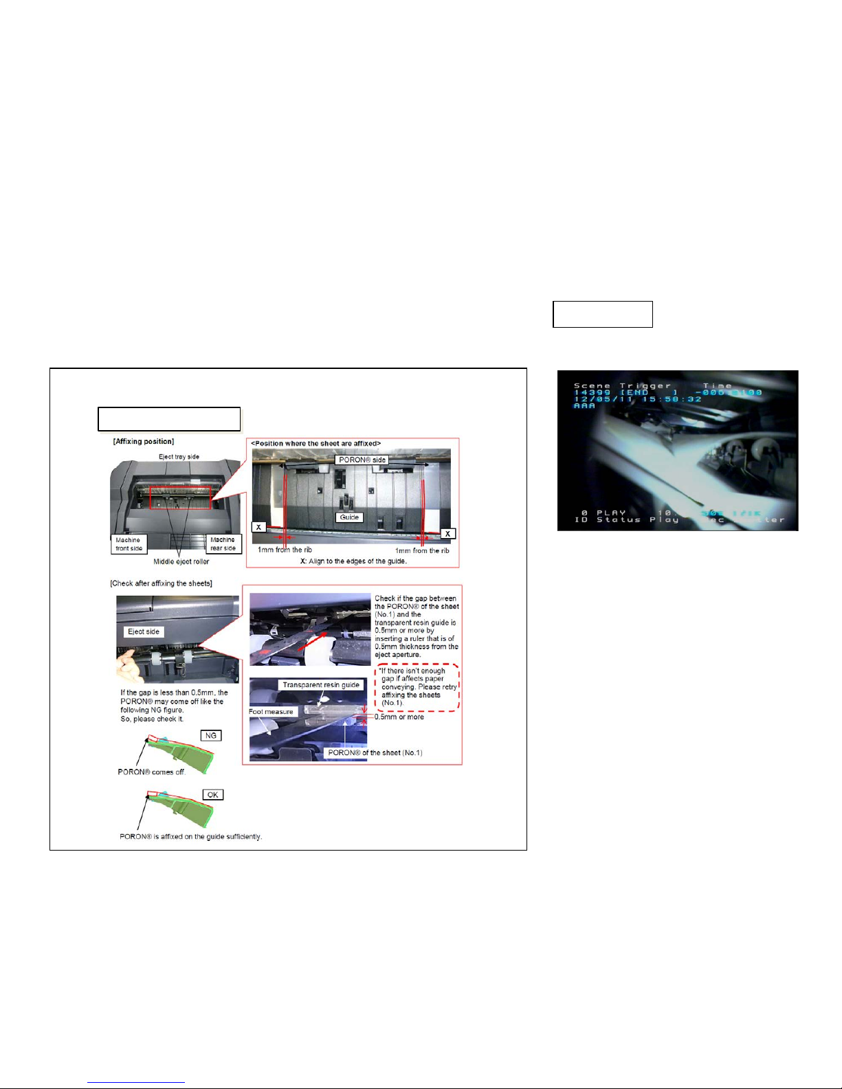
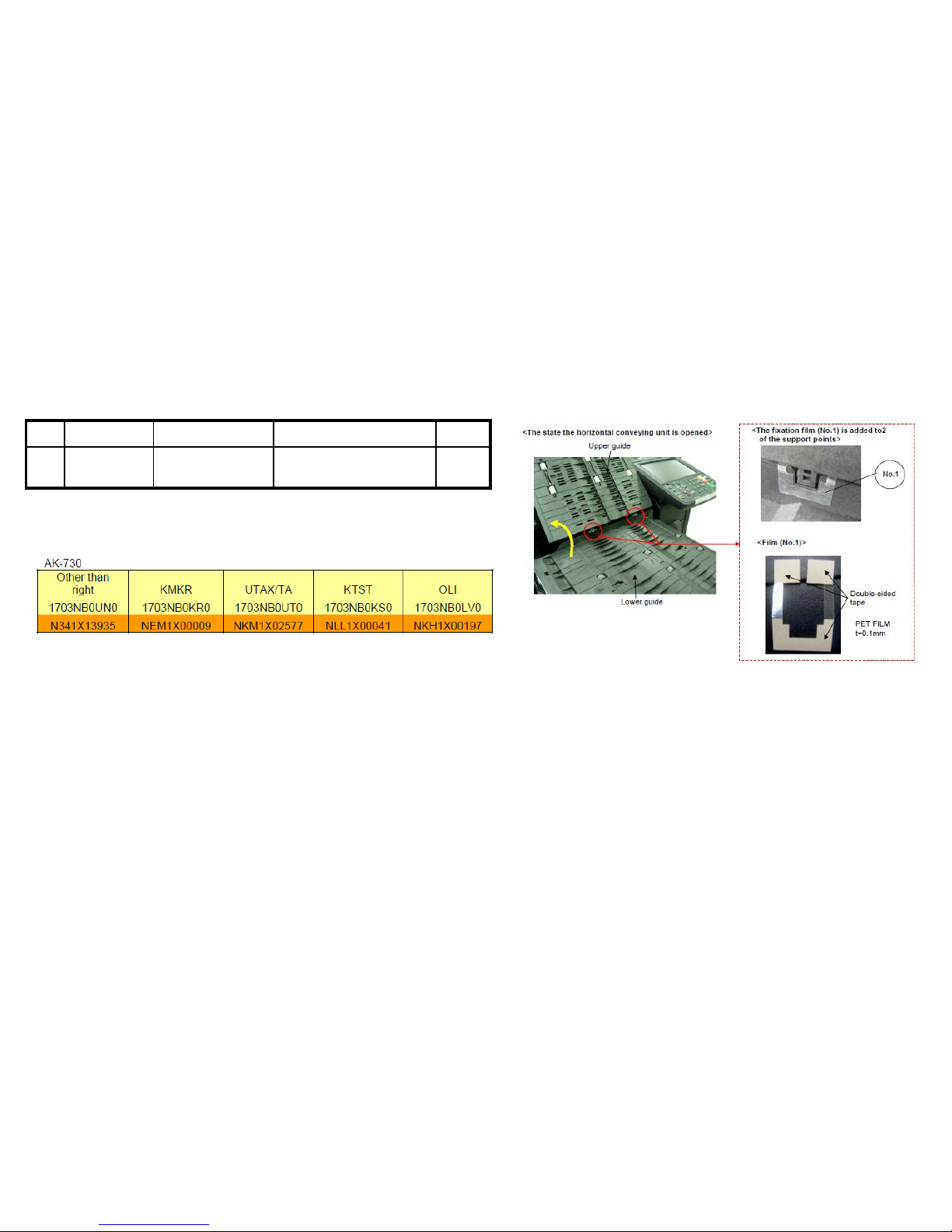
1. Add the films to the holes (2 locations )on the conveying
unit. (Fig.1)
Affix the film (No.1) to the designated location at fig after
cleaning w her e to affix it on the conveying uni t. ( F i g .2)
No. Old New Parts No Parts name Q’ty
1 302LF28820
2LF28820
SHEET RERAY
LOWER
2
Sample1 Fig 1
Fig 2
【Service bulletin】2LC-0034(B395)
■ Affected machine’s serial number is below
If J6100/J6110 occurs, check the following item 1 to 3.
J6100 / J61 10 (DF) (1/6)
8000i (2LF)
▲K DJ ▲ KDA ▲CPY KDA GSA KDBR ▲KDA 220V ▲ KDE ▲UTAX
1102LF9JP0 1102LF2US0 1102LF2CS0 1102LF2US1 1102LF2BR0 1102LF4US0 1102LF3NL0 1102LF3UT0
N4N2100074 N4P2100809 NHE2100219 NLP NextPdct NextPrdct NHF2100013 N4Q2100481 N4S2100111
▲OL IVETTI KDAU KDCN ▲KDKR ▲K DTW KDSG
1102LF3LV0 1102LF3AS0 1102LF3KS0 1102LF3KR0 1102LFTTW0 1102LF3SG0
NK12100036 NextPrdct NextPrdct NMQ2100022 NJQ2100002 NextPrdct
6500i (2LG)
▲K DJ KDA CPY KDA GSA KDBR ▲KDA 220V KDE UTA X
1102LG9JP0 1102LG2US0 1102LG2CS0 1102LG2US1 1102LG2BR0 1102LG4US0 1102LG3NL0 1102LG3UT0
N4T2100122 N4U1Z00959 NHG1Z00248 NLQ NextPdct NextPrdct NHH2100014 N4V1Z00575 N4X1Z00236
▲OL IVETTI KDAU KDCN ▲KDKR ▲K DTW ▲KDSG
1102LG3LV0 1102LG3AS0 1102LG3KS0 1102LG3KR0 1102LGTTW0 1102LG3SG0
NK22100037 NextPrdct NextPrdct NMR2100017 NJR2100003 NJL2100088
55
Page 56
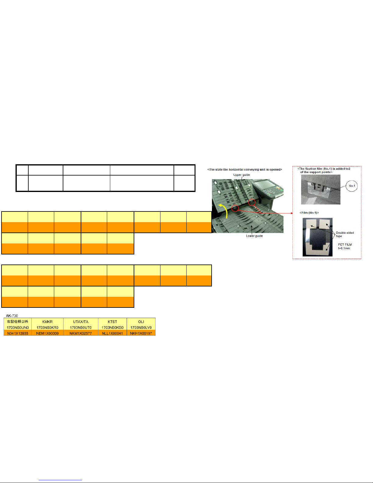
56
J6100 / J61 10 (DF) (2/6)
■Affected machine’s serial number is below
№ Old New Parts No Parts name Q’ty
1 302LF28770
2LF28770
SHEET HINGE
STOPPER
2
2. Check whether the leverage of upper conveying guide on the bridge conveying unit is not detached.
if it is detached, add the below parts as referring the procedure mentioning next page.
【Service bulletin】2LF-0004(B355)
8000i
KDA CPY KDA GSA KDBR KDA 220VI KDE UTAX OLIVETTI
1102LF2US0 1102LF2CS0 1102LF2US1 1102LF2BR0 1102LF4US0 1102LF3NL0 1102LF3UT0 1102LF3LV0
From nex t From next
production production
KDAU KDCN KDKR KDTW KDSG
1102LF3AS0 1102LF3KS0 1102LF3KR0 1102LFTTW0 1102LF3SG0
From nex t
production
6500i
KDA CPY KDA GSA KDBR KDA 220VI KDE UTAX OLIVETTI
1102LG2US0 1102LG2CS0 1102LG2US1 1102LG2BR0 1102LG4US0 1102LG3NL0 1102LG3UT0 1102LG3LV0
From nex t From next
production
production
KDAU KDCN KDKR KDTW KDSG
1102LG3AS0 1102LG3KS0 1102LG3KR0 1102LGTTW0 1102LG3SG0
From nex t (-->)
production NJR2100003
N4U1Y00818
NHG1Y00207
NHH1Y00006
N4V1Y00423
N4X1Y00183
NK21Y00021
NKQ1Y00021
NMR1Y00009
NJL1Y00084
N4P1X00646
NHE1X00173
NHF1X00011
N4Q1X00421
N4S1X00067
NK11X00024
NKP1X00011
NMQ1X00013
(-->)
NJQ2100002
NJK1X00073
Page 57
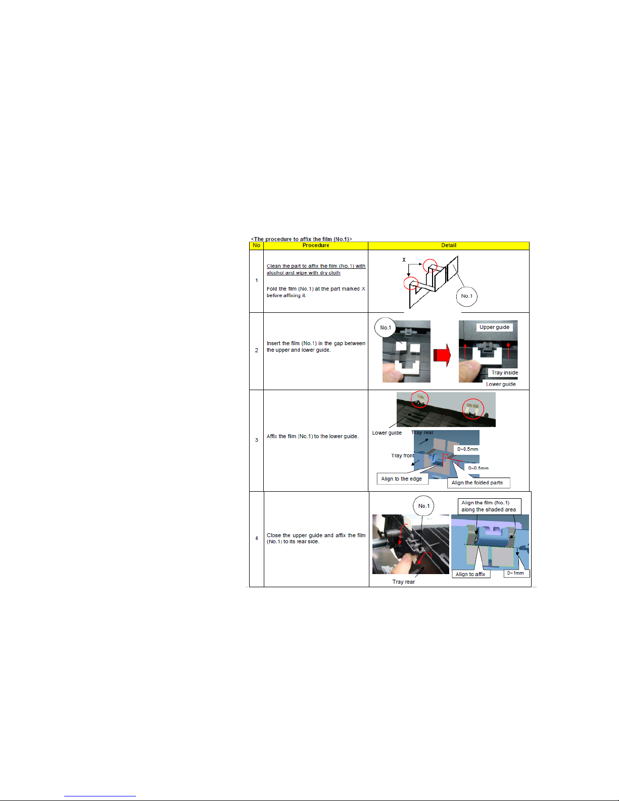
■The film attached procedure
J6100 / J61 10 (DF) (3/6)
57
Page 58
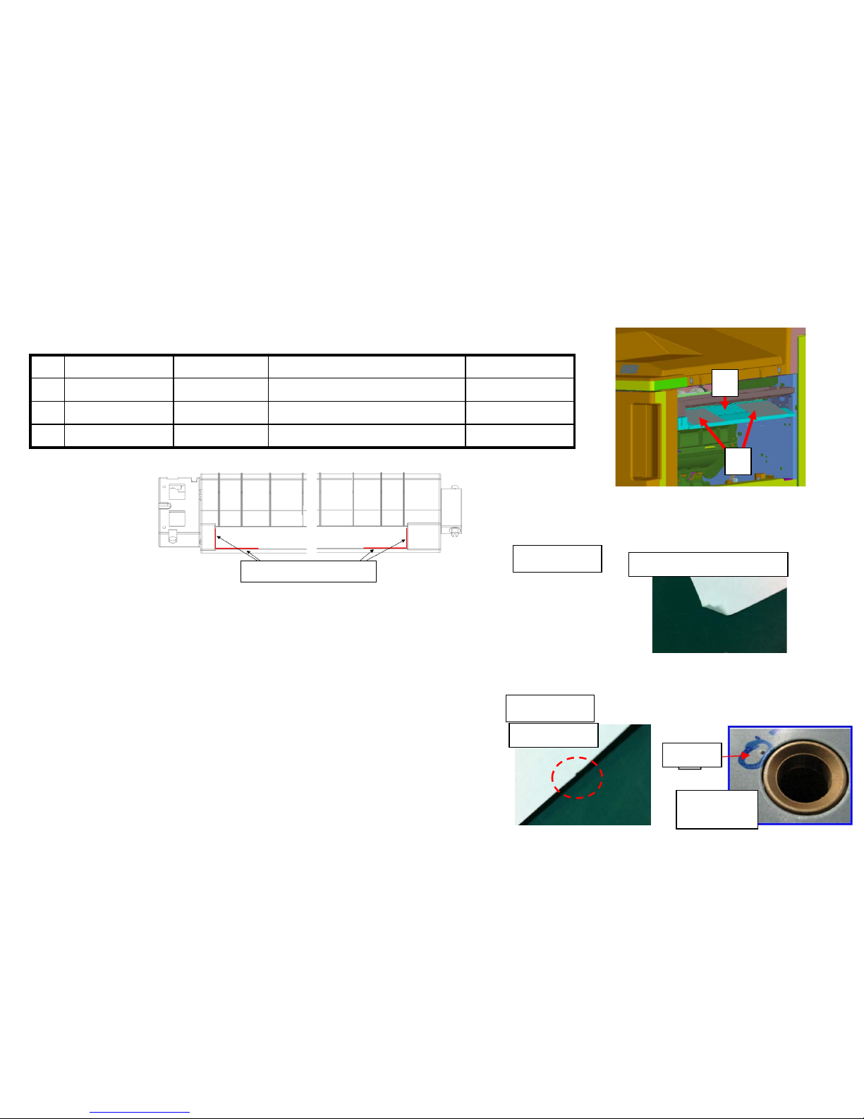
2. Replace the GUID E FEED LOWER with the No.1 P ARTS GUIDE FEED
ASSY which the No.3 PET Film is attached on.
No. Old Parts No. New Parts No Parts name Q’ty
1 303NB94250 PARTS GUIDE FEED ASSY SP 1
2 303NB07020 303NB07021 +GUIDE FEED LOWER 1
3 303NB07190 +SHEET FEED IN C 2
2
1
3. Check whether the paper corner folding or scrat chi ng oc cur s at the
Punch unit (Sample1, Sample2)
a. Upgrade the firmware (as set.)
3NB_9200.004.007 and after
3NK_9A00.003.004 and after
b, If the serial number of unit is before below
number, replace the Punch Unit.
PH-7A:N361703776 and after
PH-7B:N351700282 and after
PH-7C:N371701264 and after
PH-7D:NMY1700042 and after
Paper is caught by the convex of welding part at
the Punch unit upper guide conveying surface.
Scratch mark
Corner Folding (small fold)
Sample 2
Sample 1
The leading edge of paper (11 inch width rear side) is
caught at the hole of Punch unit upper guide plate.
J6100 / J61 10 (DF) (4/6)
<Affix position of film>
Affix it 0 to1mm from R end
Convex
Conveying
surface
58
Page 59
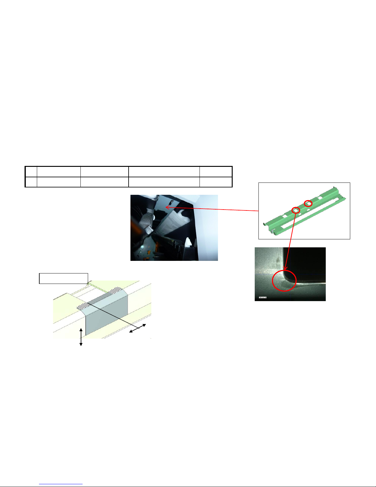
J6100 / J61 10 (DF) (5/6)
4、If the paper stop before the conveying-in roller and there is no damage on paper, check whether the paper
is caught by the STAY PUNCH.
a. Add the PET Films on the middle part of cutout of the STAY PUNCH.
STAY PUNCH
№ Old Parts Item New Parts Items Parts Name Q’ty
1 303NB07140 SHEET ROLLER FEED 2
0
1
1
1
Adhesive position for Both sided Tape
Adhesive position
59
Page 60
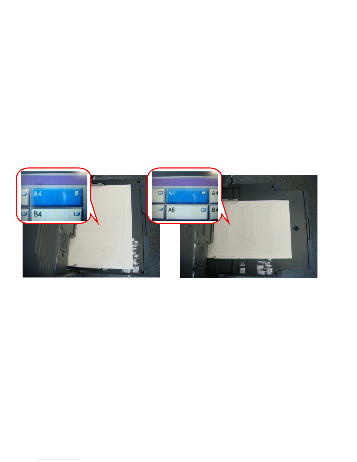
J6100/J6110 (DF) (6/6)
5. When select A4 paper size at the manual bypass tray, be careful below item.
If the actual direction of A4(Let ter)s iz e paper set on the manual by pass tray is not same as setting the direction by
the operation panel, JAM6110 may occur after feeding is started . Therefore, please inst ruct user about the setting
method of manual bypass size.
60
Page 61
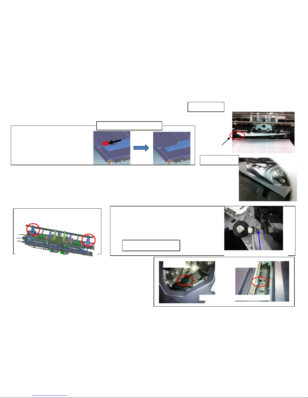
J631X / J641X / J650X (1/3)
1. Corner folding at paper leading edge or curling JAM (Image sample 1)
– It occurs since lower curled paper is caught by the cursor.
a. Replace the cursor.
2. Paper trail end folding JAM (Image sample 2)
It occurs since the opening of the Bundle discharge unit is
(b) slanting or (c) narrower.
(b) Correct the balance of the Bundle discharge unit.
(Check the front and rear opening balance by both pulleys while opening the Bundle Discharge Unit by
executing U240 MOTOR-EjectUnlock(30)
(c ) Place the MOUNT PI UPPER GUIDE
(a) Replace the cursor
303NB36031
CURSOR L MIDDLE TRAY
303NB36041
CURSOR R MIDDLE TRAY
Affected from:2012 Jan production
Ref.No.3NB-0017(C025)
(b) Correct the Gear mesh
View from main tray side
Inside of process tray
(Paper trail end side)
Corner
folding
(c) Replace the PI mount plate
303NB36321 MOUNT PI UPPER GUIDE
Affected from : 2011 Oct. production
MOUNT PI UPPER GUIDE
Ref.No.3NB-0011(B403)
Image sample1
Image sample 2
3. JAM when the JAM paper occurs at J631* is not existed at the
Processing section.
d. Check whether the Actuator (DF middle sensor) is operating
smoothly without any problem.
Actuator (DF middle sensor)
DF-790 DF-770
61
Page 62
4.curling JAM at paper leading edge (Image sample 3)
Due to paper downward curl, the leading edge of paper is round at the inner
part of the process tray and JAM occurs.
a. Please affix the films.
Image sample3
Inside of process tray
(Paper tray leading side)
(a)Affix the films
303NC24050 SHEET CONVEYING 2pcs
Ref.No.3NC-0002(C179)
J631X / J641X / J650X (2/3)
62
Page 63
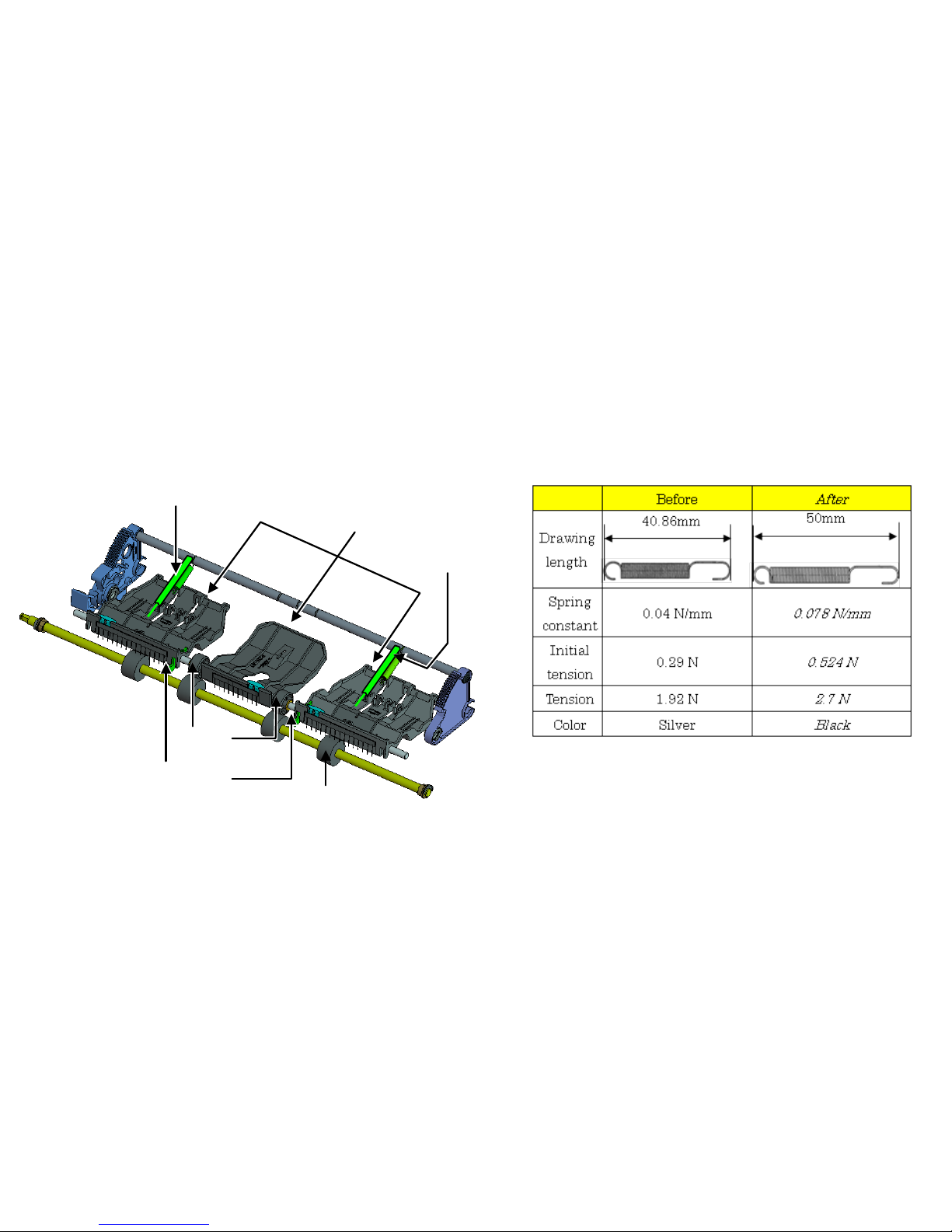
J631X/J641X/J650X (DF) (3/3)
【Service Bulletin】
3NC-0002(C179)
【Phenomenon】
When ejecting 45 to 50 sheets of paper bundle of A4R or Letter-R, it may bound and the 1st sheet of the next bundle
may be caught up at the paper guide. Then, the J6311 jam may occur.
【Hot to respond】
The tension of the spring is increased that pulls up the paper holder guide.
Eject guide
(303NB3652-)
Eject roller
Eject pulley
Spring
Paper holder guide
(303NB3622
-)
63
Page 64
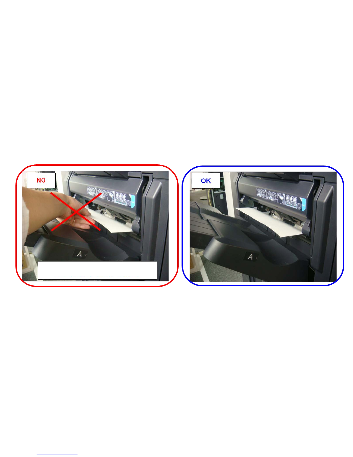
J6510 (DF-790 Caut ion of Manual Staple)
【Notes】
When inserting the paper, please make sure that the paper hold hand is away from the paper
during staple operation.
When you perform the manual staple operations when they hold the paper by hand, paper jam
(J6510) will occur.
Please do not perform the manual staple
operating with that held the paper by hand.
64
Page 65
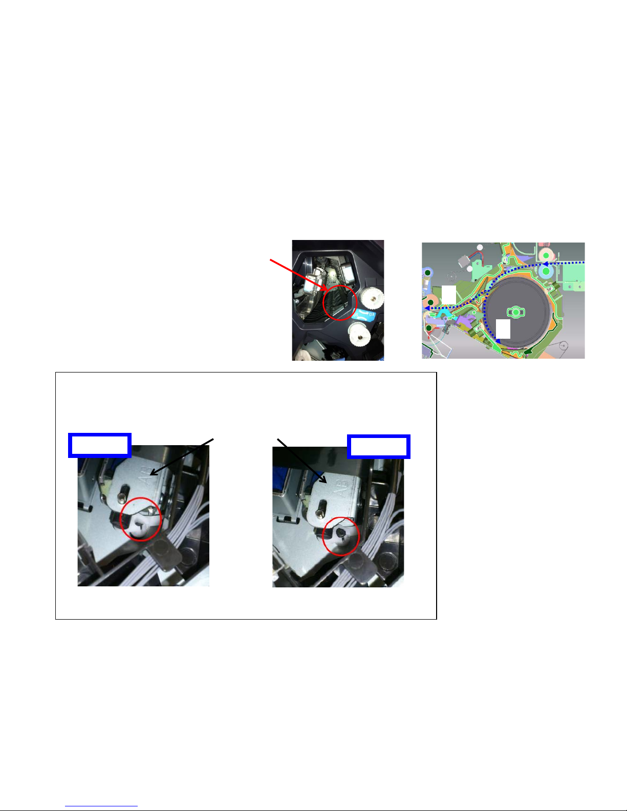
J6600 (DF-770/790)
1. JAM after paper stops at the paper conveying path
(a) The leading edge of paper is caught by the Feedshift guide 1
(b)Paper is fed to the direction2 instead of the direction1.
(a) Check the assembling condition of the Feedshift guide1.
Check the shaft of Feedshift guide 1 is firmly inserted into the lever of DF feedshift
solenoid 1. In case of out of location, insert the shaft into level as shown in below photo.
DF feedshift solenoid 1
NG
OK
Feedshift guide 1
2
1
65
Page 66
J6710/J7710(BF)
BF lock lever
DF fix pin
1. J6710/7710 occurs, t ake the following measure.
a. The JAM paper is stopped before reaching the BF.
No. Old New Parts No Parts name Q’ty
1 303ND02280 303ND02281 FULCRUM PLATE
RELEASE
2
2 303ND02360 PIN HOOK BOOKLET 2
OLD→NEW
2. DF hook pin
OLD→NEW
1. Fulcrum pin for BF lock lever
Paper stop position
BF
<Paper stop position>
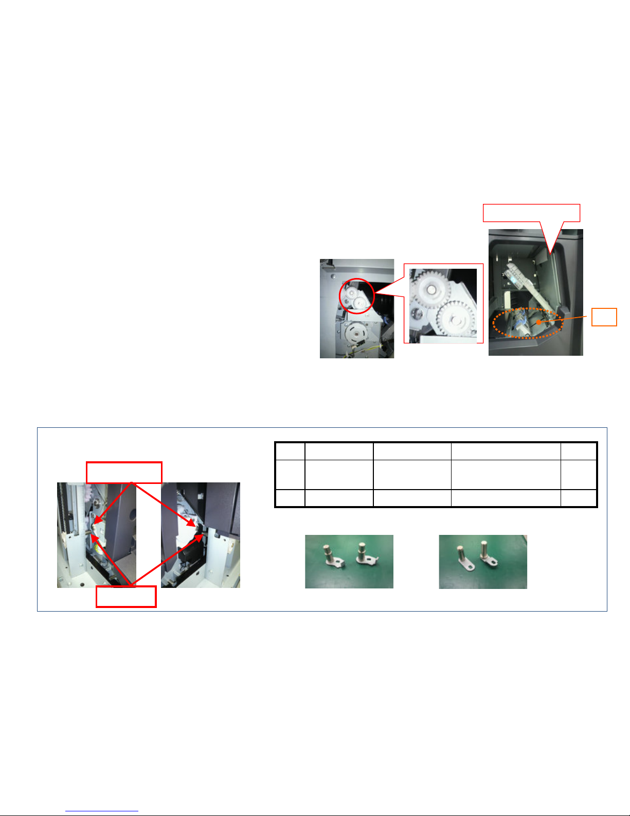
If the gears are not engaged, replace the fulcrum pin (1) of
BF lock lever, DF hook pin (2).
b. Check whether the mesh of gears is not engaged or not after
setting the BF into the DF.
66
Page 67
J9020/J9030
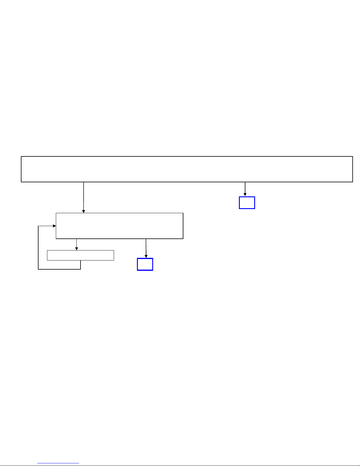
<Treatment 1>
The function can be stopped after setting is OFF.
< Treatment 2>
If the user request below demand, Keep U460 set ON and do not stop this detection function.
a. Reduce the original damage in case of setting the stapled originals wrongly on DP.
b. Prevent missing page due to multi feeding (except DF-771)
Download the firmware
higher than Service Upgrade
Pack Ver. V3.03
[System menu] [Common] [Error handling setting] [Original skew or multi feeding]
Check firmware version by U019
MAIN:Ver.003.077
MMI :Ver.003.074
Output the maintenance report from the maintenance mode U000 and if the count of J9020(skew original feed
detection))/J9030(muti feeding detection) *1 is frequent, perform below either t reat men t 1 or 2. *1 DP-771 has no
J9030 detection function.
Before Higher
Detect Stop the function
[Stop feeding by error ] [Ignore]
User can be selected whether set on this detection function.
Perform the maintenance mode U460 (Adjust Feed Sensor ) to stop this detection function.
<Procedure> (It can be performed when DP is installed.)
[U460 Adjust Feed Sensor] [DP] [on/off Config] [ON OFF] [Start
]
67
Page 68
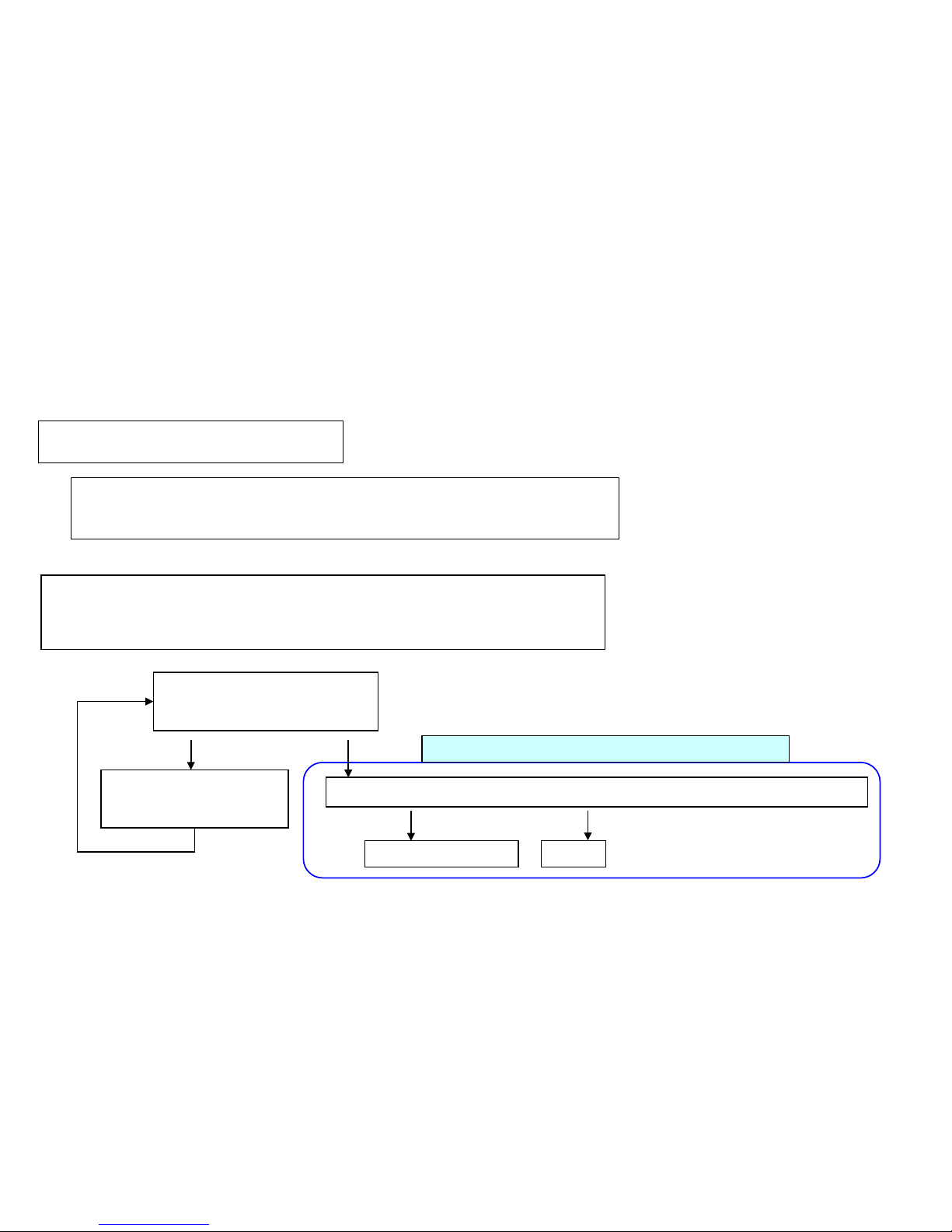
Check the maintenance report or U903 (JAM counter), check whether bel ow counter are counted up.
8000i/6500i//DP-771: J9010 J901 1 J9110 J9300 J9310 J9400 J9600
DP-770 : J9010 J9110 J9600 J 9610
Check the DP firmw ar e version at U019
8000i/6500i//DP-771:3M4_9500.007.002
DP-770 : 3NV_9500.005.001
OK
No count Count up
2.J9010 J901 1 J9110 J9300 J9310 J9400 J9600 J9610 occurs, take the following measure.
Download the DP firmware
Before
After
OK
J9010/J9011/J9110/J9300/J9310/J9400/J9600/J9610
68
Page 69
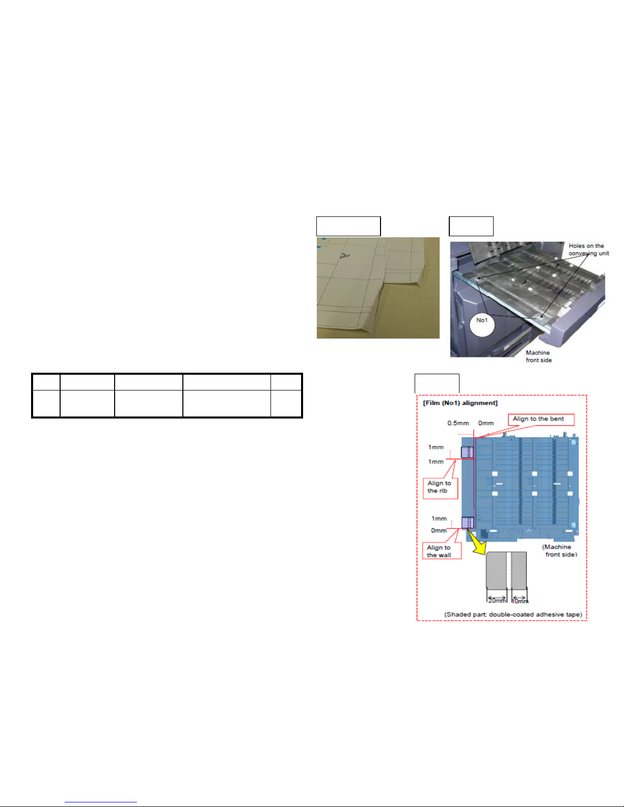
1.If it occurs at lower tray ejecting , per form below a, b.
(at DF-770 install: A tray eject/ at DF-790 installed: A, B
tray eject)
a. Add the films to the holes (2 locations )on the conveying
unit. (Fig.1)
Affix the film (No.1) to the designated location at fig after
cleaning w her e to affix it on the conveying uni t. ( F i g .2)
No. Old New Parts No Parts name Q’ty
1 302LF28820
2LF28820
SHEET RERAY
LOWER
2
Sample1 Fig 1
Fig 2
【Service bulletin】 2LC-0034(B395)
■ Take the measure at the production machines after 2011 Nov.
If Corner Folding occurs at paper , check below item.
Corner Folding (1/6)
69
Page 70
■Affected machine’s serial number is below
No. Old New Parts No Parts name Q’ty
1 302LF28770
2LF28770
SHEET HINGE
STOPPER
2
b. Check whether the leverage of upper conveying guide on the bri dge conveying unit is not detached.
if it is detached, add the below parts as referring the procedure mentioning nex t page.
Corner Folding (2/6)
【Service bulletin】 2LF-0004(B355)
70
Page 71
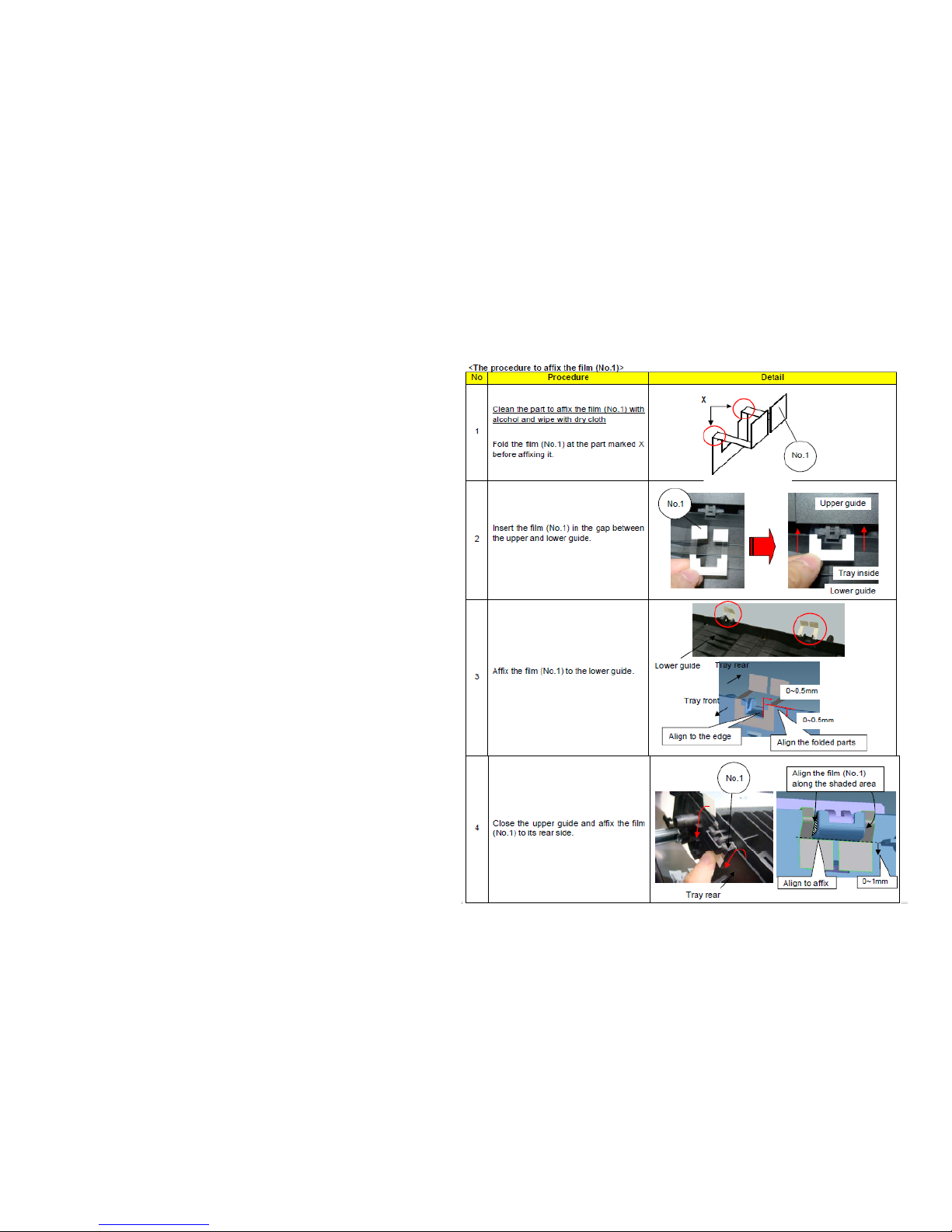
■The film attached procedure
Corner Folding (3/6)
71
Page 72
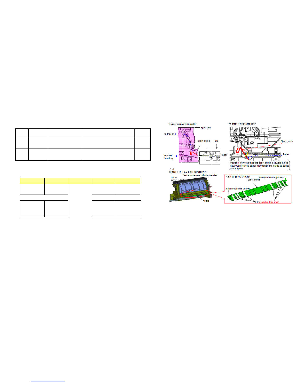
2. If it occurs at ejecting paper to upper tray (at DF-770 ins tal l : B tr ay eject/ at DF-790 installed: C
tray eject), replace with new guide (No.1) which is affixed the films or the Relay exit unit (No,2).
No. Old New Parts No Parts name Q’ty
1 303NB94190
3NB94190
PARTS GUIDE RELAY EXIT
SHEFT SP
1
2 302LF94173
2LF94173
PARTS RELAY EXIT SP 1
【Service bulletin 】2LH-0005(B445)
■Affected machine’s serial number is below.
AK-730
右仕様以外
KMKR KTST UTAX/TA OLIVETTI
1703NB0UN0 1703NB0KR0 1703NB0KS0 1703NB0UT0 1703NB0LV0
N341Y17217 NEM1Y00012 NLL2100056 NKM1Y02982 NKH1Y00215
KDA CPY KDA CPY
1102LJ2US2 1102LJ2CS1 1102LH2US2 1102LH2CS1
NWQ1Y00001 NWP1Y00001 NWN1Y00001 NWM1Y00001
▲TASKalfa4500i (AK)
▲TASKalfa5500i (AK)
Corner Folding (4/6)
72
Page 73
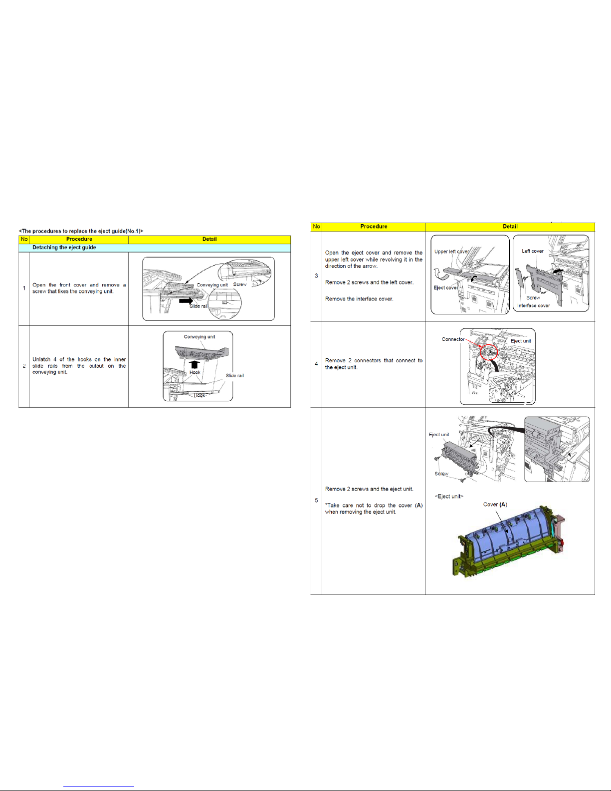
Corner Folding (5/6)
73
Page 74
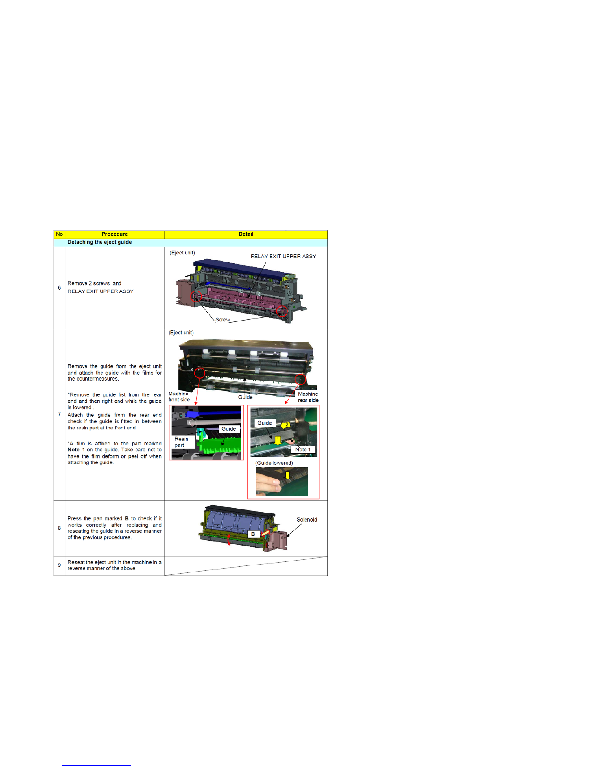
Corner Folding (6/6)
74
Page 75
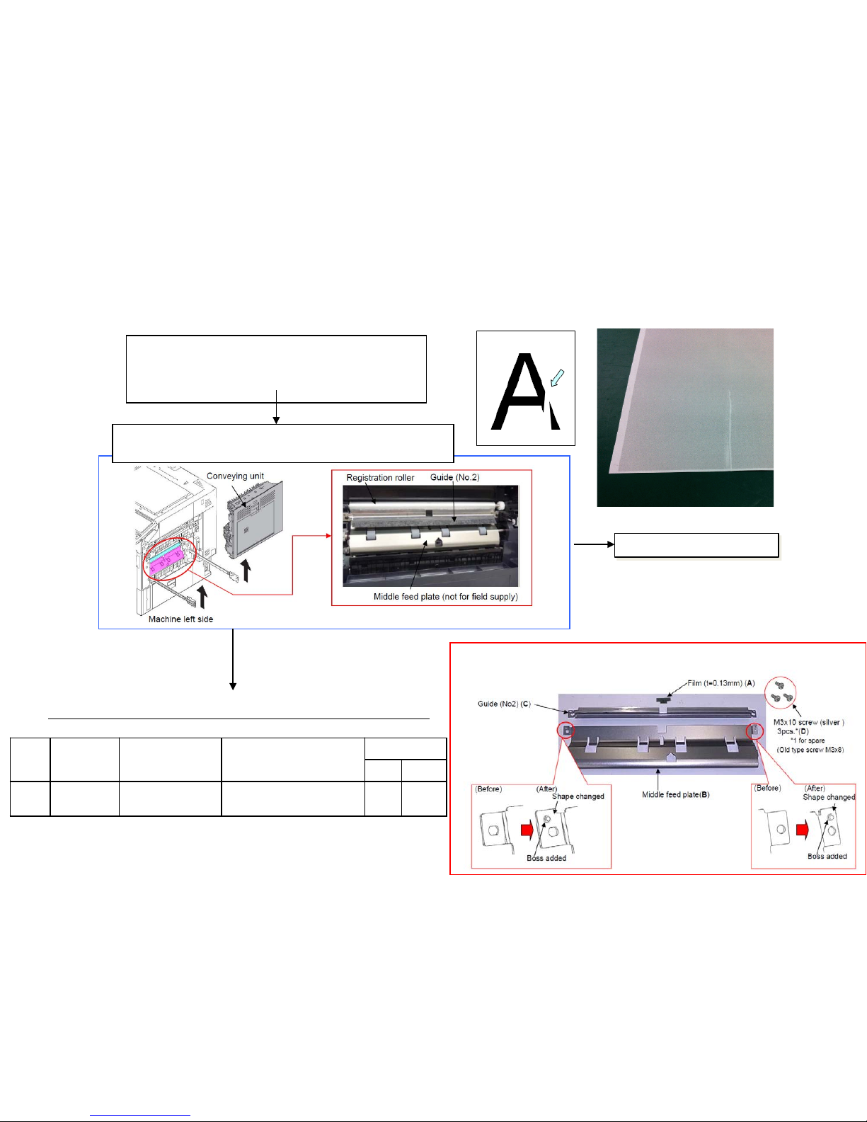
75
NO
Perform above
service bulletin
measurement
contents.
If the paper creasing like a below image occu rs f r equ ent l y, check as referring to below procedure.
Paper Creasing (1/2)
Ref.No. 2LC-0013(B213)
<Check the image sample>
On the image sample of creased paper, spread out
the creased part and check if toner is not transferred
to the creased
If the paper is above creasing condition, check whether modified
guide below photo is equipped or not.
YES
Add the modification guide (refer to next age for i nstal l ati on)
■ PARTS REGIST GUIDE SET SP (No1) components parts---A to D
No.
Old Part
No.
New Part
No.
Description
Q’ty
Old New
1 ----------
302LC94690
2LC94690
PARTS REGIST GUIDE
SET SP
- 1
Page 76
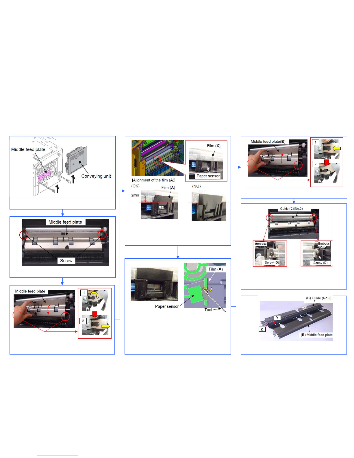
[The procedures to install the guide]
1. Remove the conveying unit.
2. Remove 2 of the screws that fix the middle feed plate.
3. Remove the middle feed plate after rotating it
downward as in the figure right.
4. Overlay the film (A) bundled in the parts set
(No.1) on the film (X) affixed on the paper senor as
shown in figure.*Clean where to affix the film.
Fold the leading edge of the film (A) and affix it
toward inner side using a flat-blade
screwdriver, etc.
[Note]
Take care of the tool not to touch the paper
sensor.
Securely fold the film or mis-sensing may occur.
<Note>
Check if the film is not warped toward Z before fitting the
guide (C) (No.2). If warped so, correct the warpage.
6. Fit the middle feed plate (B)
7.Put the guide (C)(No.2) on the middle feed plate (B) and
fix them with M3x10 screw (D)(Total 2 points)
*Check the guide (No.2) does not run over the emboss
Paper Creasing (2/2)
76
Page 77
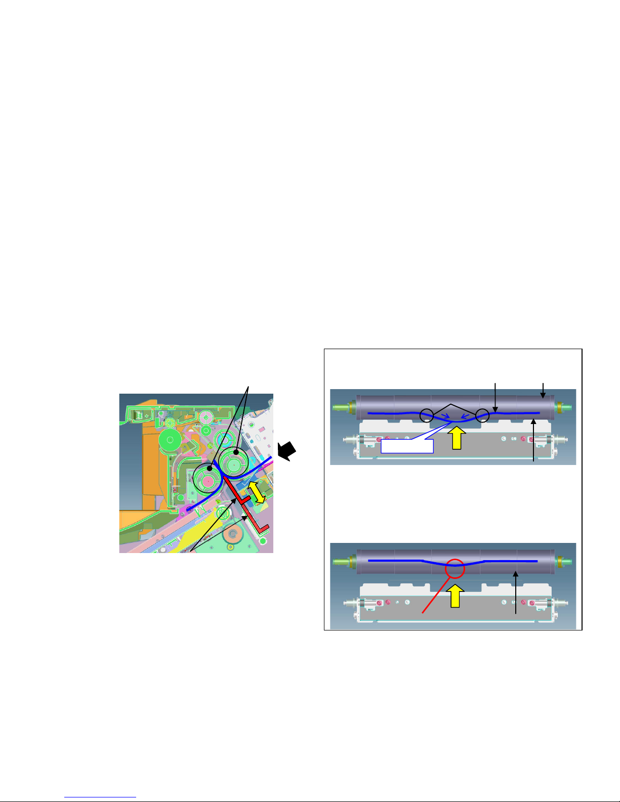
BF-730/720/710 Measure for Paper creasing when a sheet of
paper is fed after middle folding
【Phenomenon】
When center-folding or tri-folding one sheet of paper with the downward bending (toward the CF blade side) at its central
part, the paper center part of paper may be creased or damaged due to the paper’s bent part pinched up by the CF rollers
and the CF blade.
【How to Respond】
When the below phenomenon occurs, please execute the following 1 to 3 in order.
1.Set the positions of the paper length guide and the paper width guides in the paper cassette in order to properly fit the
paper size.
2.Turn the papers in the paper cassette over and reinstall it. (The grade of the paper’s bending may be slightly improved)
3.Replace the CF blade (303J124142:BLADE MID PRESSING) with the new one.
【Service Bulletin】
3ND-0008(C296)
[Cross-section view of the center-folding unit]
CF rollers
CF blade (No.1):
CF blade lifts up to fold the paper (indicated
with the blue line in the above figure) when
center-folding or tri-folding the paper.
<View from the arrow X>
(Before: Below is the state of lifting up the CF blade)
(After)
CF roller
Old CF blade
New CF blade
Protrusion is added
Y
Bent part
Paper
If the CF rollers pinch up the paper's bent
part that cannot be passed to the other
area due to pressing two points marked Y
by
the CF blade lifting up, the paper may
be creased or damaged.
77
Page 78
C0640 (HDD error)
C0640 display on the operation panel LC D at turning on the main sw.
Check the cable, connecter bet ween H DD and
Main PCB. (check poor connection, break,
damage
<Connect applicable for main PCB>
5500i/4500i/3500i :
YC1、YC27
Replace the cable
Check abnormal
sound (rattling sound)
during driving HDD
Initialize HDD: *
1. Execute U024.
2. Select “FULL” and start format.
3. Power OFF/ON.
Replace HDD
HDD Item code
5500i/4500i/3500i :
302LH93070 PARTS STORAGE DEVICE SP
OK
HDD related cable item code:
5500i/4500i/3500i :
302K946A10 WIRE HDD POWER
302K946A20 WIRE HDD DATA1
OK
* HDD initialize :
Stored data in HDD wi l l be erased
after this format.
NG
NG NG
78
Page 79
1. In case of abnormal sound occurs
a. Replace the DLP UNIT .
b. Re-assemble it as referring to below attenti on 1.
2. In case of no abnormal sound (developing driv e possible)
a. Remove the INNER UNIT.
b. Check the CASS SHUTTER of the DLP U NI T.
c. If the parts is broken, replace the DLP UNIT.(Fig.1)
d. Re-assemble it as referring to below attention 1.
3. In case of not applicable above 1,2.
a. It is possible of error at the DLP motor. Check the DLP motor.
C2101(Developing Motor Error)
Normal Break (bend)
CASS SHUTTER
CASS SHUTTER
Fig.1
When pushing in the CASS LOCK release LEVER at the INNER UNIT, there is a
case not to push in smoothly .
In that case, without pushing in by force, re-install the INNER UNIT while shifting it
by right-hand side and fix.
If it pushes into INNER UNIT forcefully, the lock release cannot be done normally,
C2101, C7101, and unusual sound occur again and DLP UNIT may damage.
The measure against below condition was taken after 2011 Oct. production. Therefore,
below action is not necessary if the production month is O ct. and after.
attention 1
There is a possibility that DLP is LOCKing by jam in the developing powder outlet etc.
(It may be accompanied by the unusual rattling sound lik e no engagement of gears and C7101)
79
Page 80
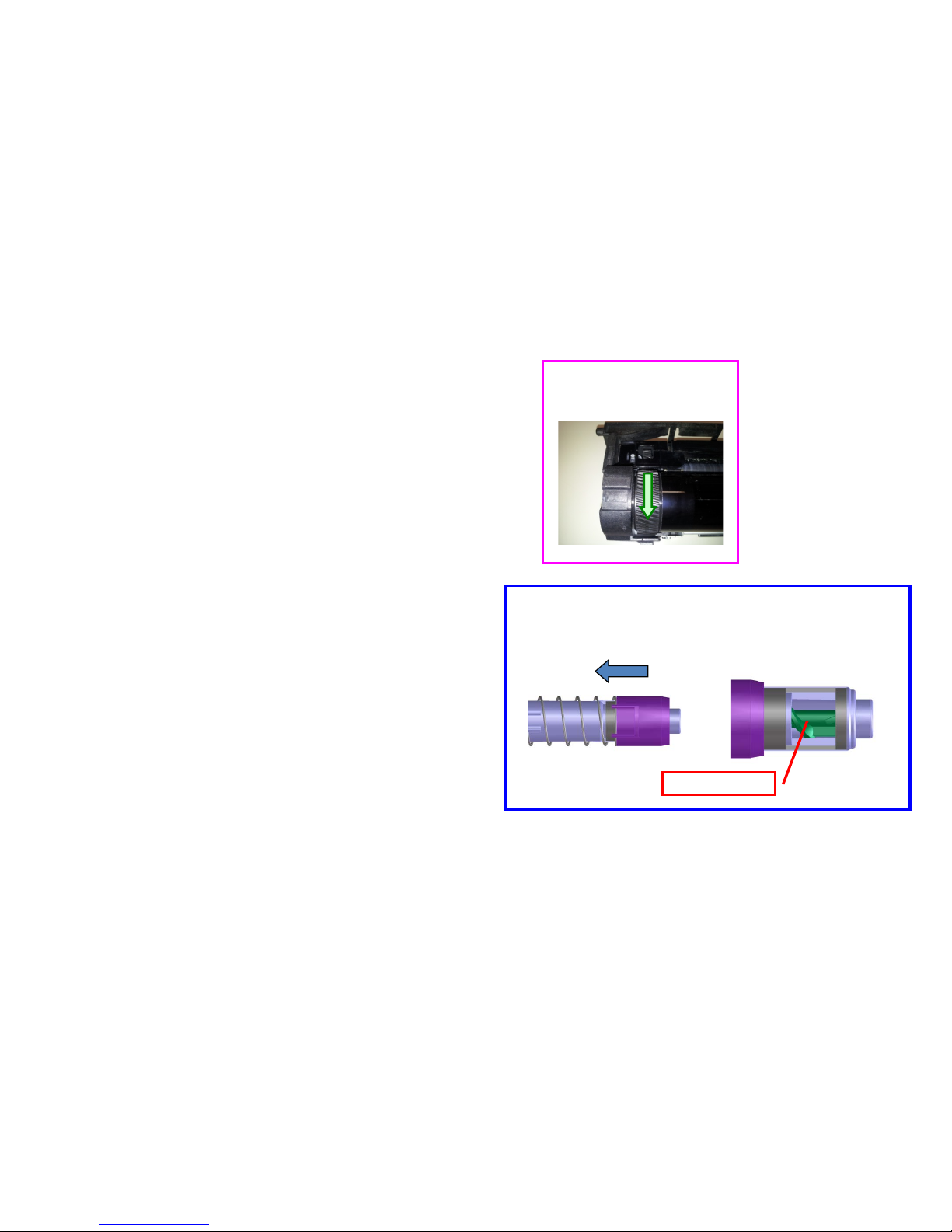
C22XX(Drum Motor Error)
If C22XX(drum motor error) occurs, take the following
measure.
a. Remove the DRUM unit from machine.
b. Check the drum rotation (refer to Fig1)
In case of no rotation, replace the drum unit
skip to “e”.
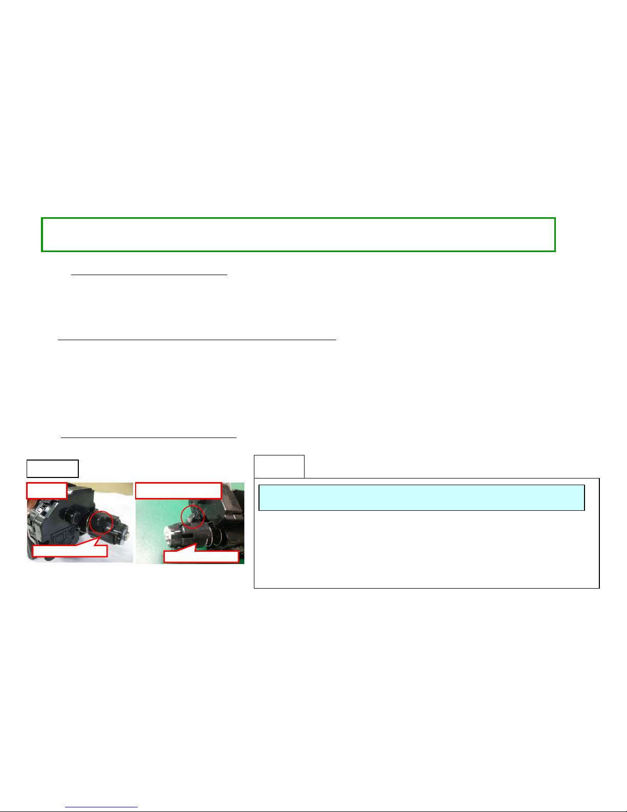
c. Check rotation of the drum spiral roller (refer to Fig2)
In case of no rotation, replace the drum unit,
skip to “e”.
d. Replace the engine PCB.
e. Check the Firmwar e ver si on and version up to above
Upgrade Pack Ver. V3.03.
<Fig2 Check Spiral Roller Rotation
Check whether the spiral roller is rotating when turning the
drum manually.
Spiral roller
<Fig1 Check Drum Rotation>
Turn it below direction.
80
Page 81
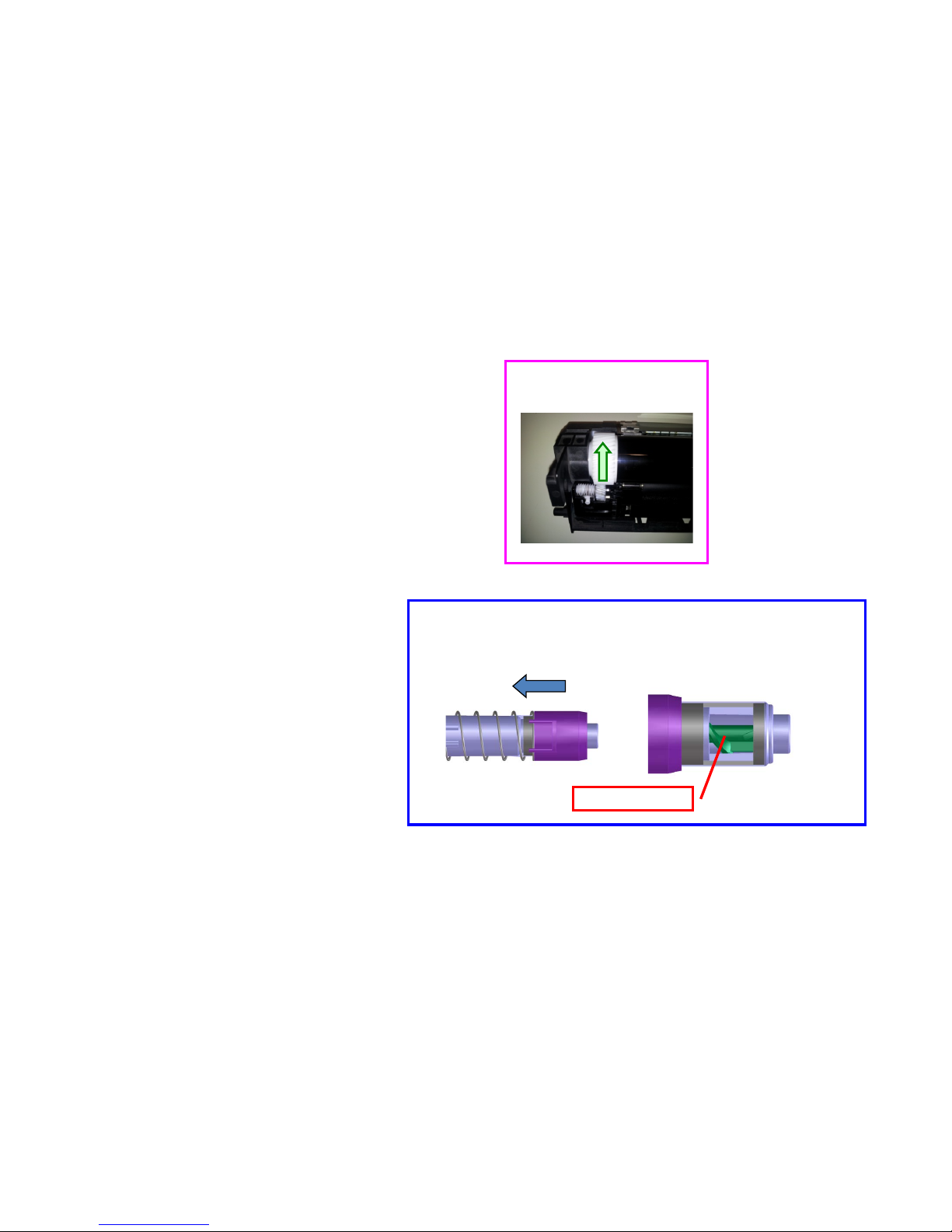
1. C510X
Main HVT error
Check the Firmware version and version up to above FW PACK V3.07.
Please check the following a-f, when a problem is not solved.
a. Remove the DRUM unit from machine.
b. Check the drum rotation (refer to Fig1)
In case of no rotation, replace the drum unit
c. Check rotation of the drum spiral roller (refer to Fig2)
In case of no rotation, replace the drum unit.
d. Check the poor connection of cleaning lamp connector.
e. Replace the HVT PCB.
f. Replace the engine PCB.
<Fig2 Check Spiral Roller Rotation
Check whether the spiral roller is rotating when turning the drum manually.
Spiral roller
C510X
<Fig1 Check Drum Rotation>
Turn it below direction.
81
Page 82
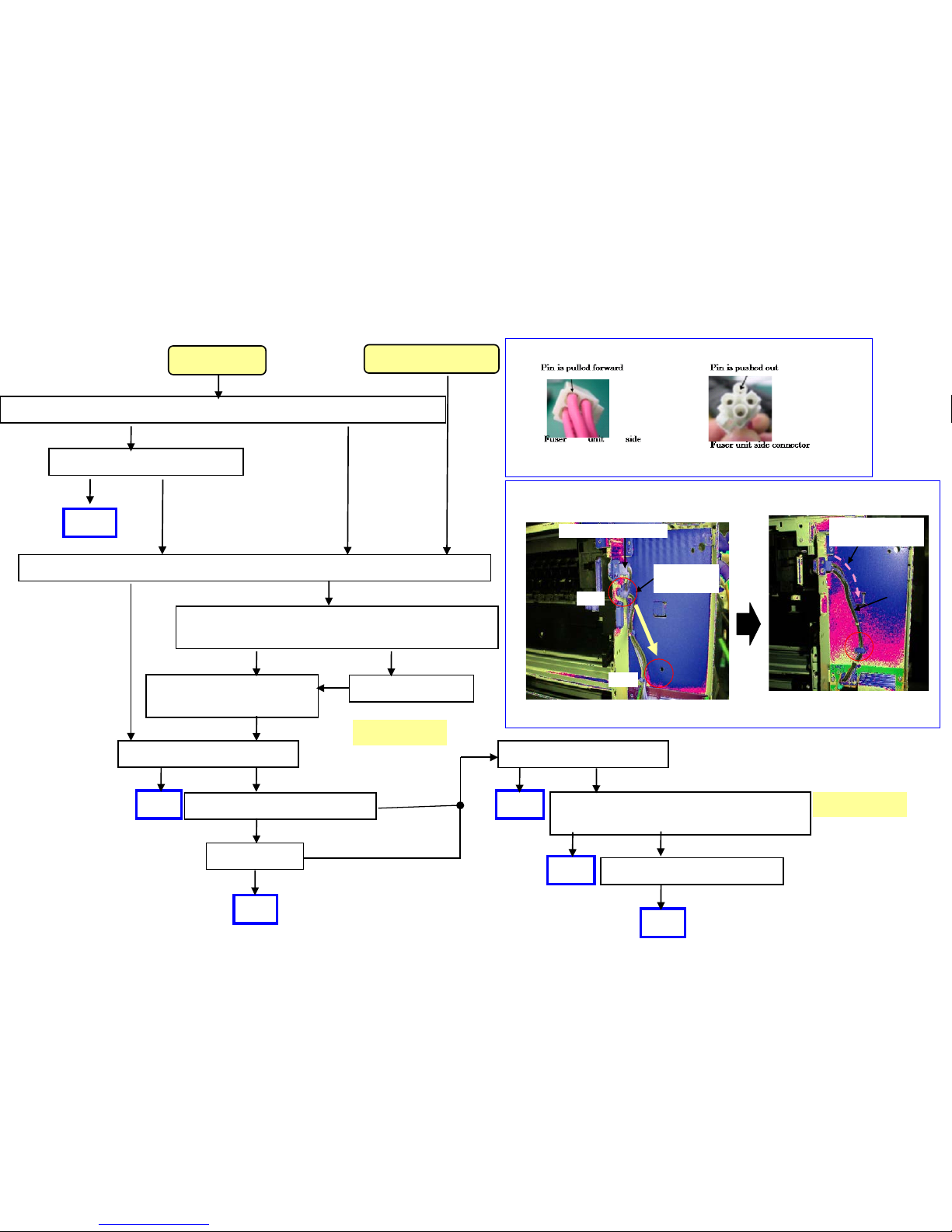
C6000(Fuser heater broken),C6030(Fuser thermistor1 broken), C6050(Fuser thermistor1 low temp error)
C6200(Fuser edge heater broken), C6230(Fuser thermistor2 broken), C6250(Fuser thermistor2 low temp
error)
Check whether the contact of fuser unit connection connector is removed.
NG
OK
Check the harness pin at the main machine side is
not removed.
OK
OK
N
G
Change harness
Change of cable wiring at
main machine side.
O
K
Replace the fuser unit
Change of cable wiring
<Check the removal of pin>
Check that the contact is not removed while pulling it lightly.
NG
Check YC26 on engine PCB
Check whether version of engine firmware is [2LF_1000.003.083]or after.
O
K
Version up the firmware
N
G
O
K
OK
N
G
C6030
Other than C6030
OK
NG
302LH46120
Re-insert
NG
O
K
OK
Replace the engine PCB.
O
K
OK
N
G
Replace the harness between engine
PCB and fuser unit.
Replace the heater PCB.
OK
OK
NG
302H746191
OK
OK
<The access saddle relocated>
Wire from connector is
smoothly aligned
Wire alignment: after
Before
Main machine side harness
Wire alignment: before
Access saddle
relocated
After
For 3500i/4500i/5500i
82
Page 83
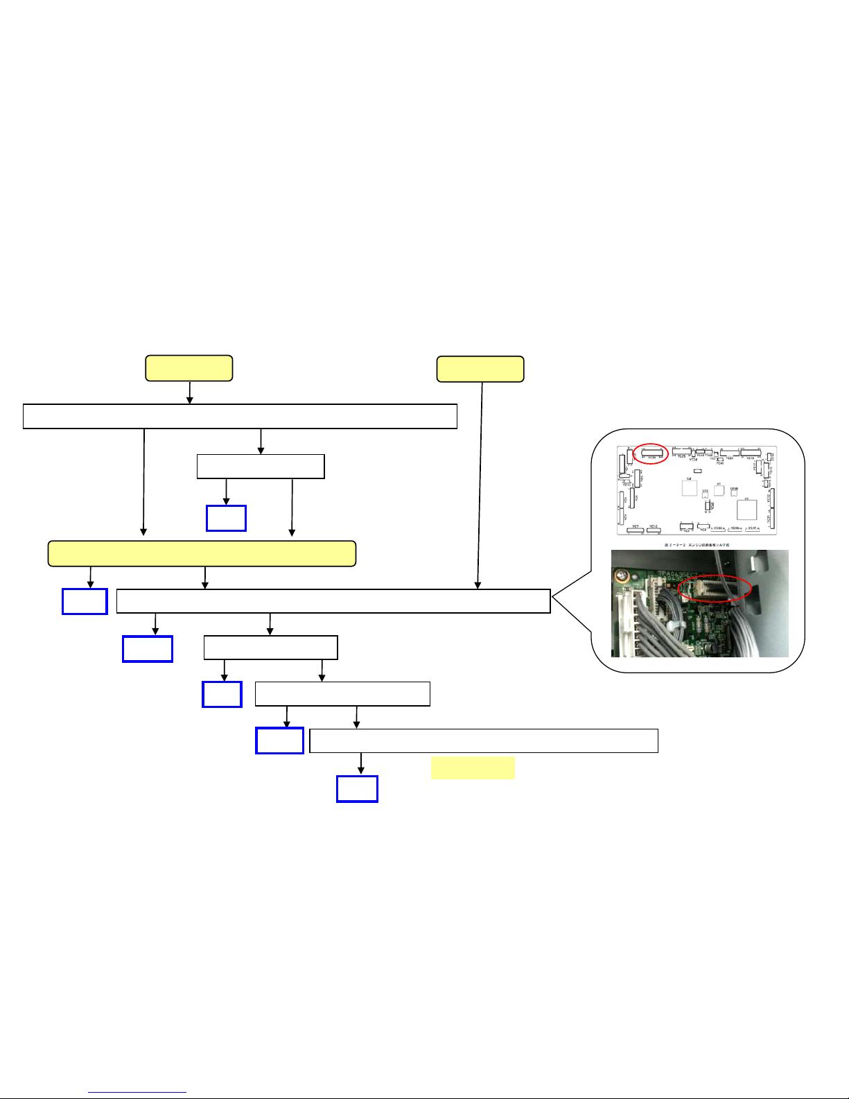
C6020/C6220(Abnormal high temperature detected by Fuser thermistor)
Check whether the version of engine firmware is [2LF_1000.003.083]or after.
Version up firmware
N
G
O
K
OK
N
G
O
K
YC26
C6020
C6220
302H746191
If C6020/C6220 occurs, take the following measure.
Check the poor connection on the engine PCB YC26
OK
OK
Check the poor connection between the fuser unit and main unit connection part.
NG
OK
Replace Fuser unit
Replace the engine PCB OK
OK NG
OK NG
OK
Replace the harness between the engine PCB and Fuser unit.
OK NG
OK
OK
For 3500i/4500i/5500i
83
Page 84

C6020 (Abnormally high fuser thermistor 1 temperature)/C6030(Broken fuser
thermistor 1 wire)/The fuser press roller may melt and stick./Poor Fusing
Please be required following the below cases such as C6030/C6020/The fuser press roller
may fuse and stick./The fuser failure.
1.Please upgrade the firmware to the Upgrade Pack Ver.V3.07 or later.
2.When the phenomenon is not cleared even if upgrading, please replace with the new fuser
unit as below.
FK-6305(100V) :302LH93042~
FK-6306(120V) :302LH93052~
FK-6307(220V) :302LH93062~
FK-6307(CHN) :302LH9C062~
FK-6307(KR) :302LH9K062~
FUSER 110 H UNIT(TW):302LH93082~
For 3500i/4500i/5500i
【Service bulletin】 2LH-0011(C172)
84
Page 85
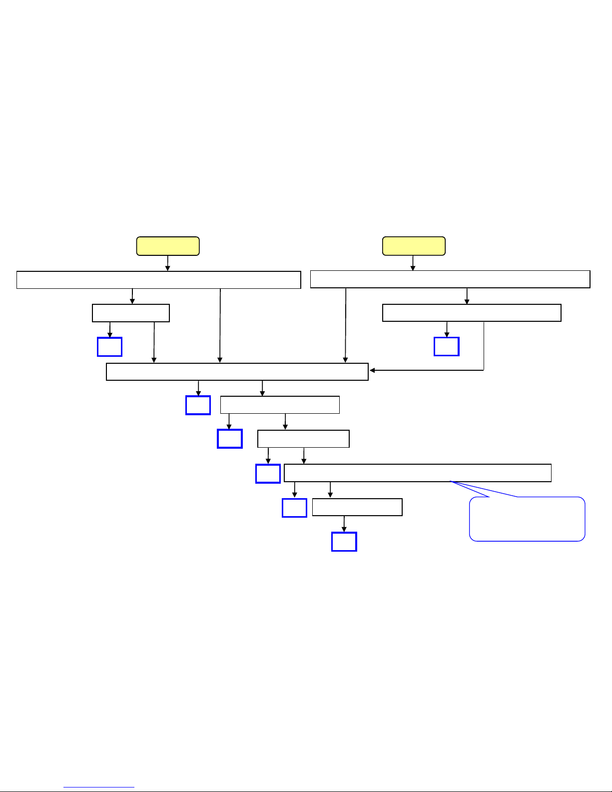
C6030(Fuser thermsitor 1 broken), C6050 (Abnormal l ow temperature
detected by Fuser thermistor 1)
Check whether the engine firmware Is above [Upgrade Pack Ver. V3.06]
Firm Version UP
NG
C6030
Replace the Fuser unit
Replace the engine PCB
C6050
OK
Replace IH PCB
OK
OK
Replace the IH coil
OK
Replace the harness between the engine PCB and the fuser unit.
OK
OK
NG
OK
NG
OK
NG
OK
NG
OK
OK
Check whether the voltage drop occurs (NG less 70V during operation)
OK
Change the power code connection.
NG
OK
OK
NG
Item code for harness
6500i/8000i :302K946590
OK NG
85
Page 86
NO
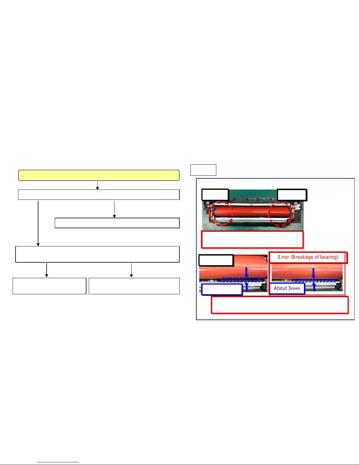
C6600/C6720
Check whether the fuser belt is broken.
YES
Judge the fuser belt slackness as referring to content of right fig. (Fig.1)
“Take a measure for “a.”
(refer to next page)
Error
Take a measure for “a.” ”b.” (refer to next page)
Normal
“Take a measure for “c.”
(refer to next page)
FRONT
REAR
Check the slackness of belt tension at
FRONT/REAR.
Normal
Error (Breakage of bearing)
about 6mm
About 3mm
■If the bearing is broken, the slackness of belt tension
becomes large and above clearance is increased.
Procedure the check the fuser belt slacking condition
Fig 1
If C6600/C6720 o ccu rs, acco rd in g t o the below
checking procedure, find the solution for a to c.
C6600(Fuser Belt Rotation Error)/C6720(Fuser IH Belt
Rotation Error)/Fuser Belt Failure
For 6500i/8000i
86
Page 87
b. Check the machine’s serial number whether its number is before taking the measure (use the jig to adjust the
fuser position plate) during the production.
If the machine’s serial number is before affected number, perform the correctiv e measure as referring to the serv ic e
bulletin No. 2LF-0003 (B345).
1) Check the fuser belt shift amount according to the content of the bulletin and
judge whether i t is necessar y to affix the film or not.
2) If affixing the film is necessary , af fix ing t he film to the fuser position adjust ment
plate and adjust the height.
<Affected machine’ s serial number for taking the measure during the production>
a. When replacing the fuser unit, it exchanges for the fuser unit applicable to the end of the right figure.
Mo del spec Par t No . Description Mode l spec Part No. Description
100V
302K993115 FK-8705
100V
302LF93045 FK-6705
120V
302K993125 FK-8706
120V
302LF93055 FK-6706
200V
302K993135 FK-8707
200V
302LF93065 FK-6707
KDKR
302K99K135 FK-8707(KR)
KDKR
302LF9K065 FK-6707(KR)
Mercury
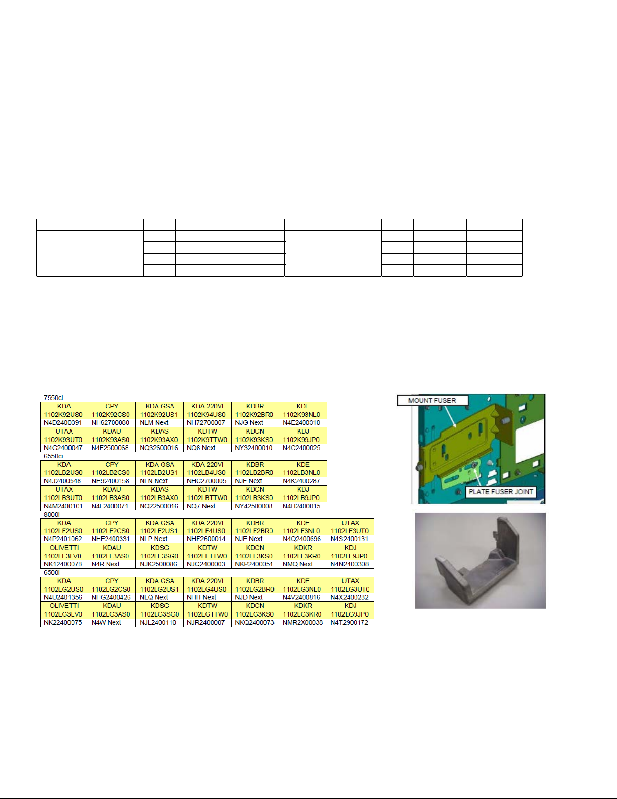
(TASKalfa 7550ci/6550ci)
Zeus
(TASKalfa 8000i/6500i)
C6600(Fuser Belt Rotation Error)/C6720(Fuser IH Belt Rotation Error)
/Fuser Belt Failure
For 6500i/8000i
87
Page 88
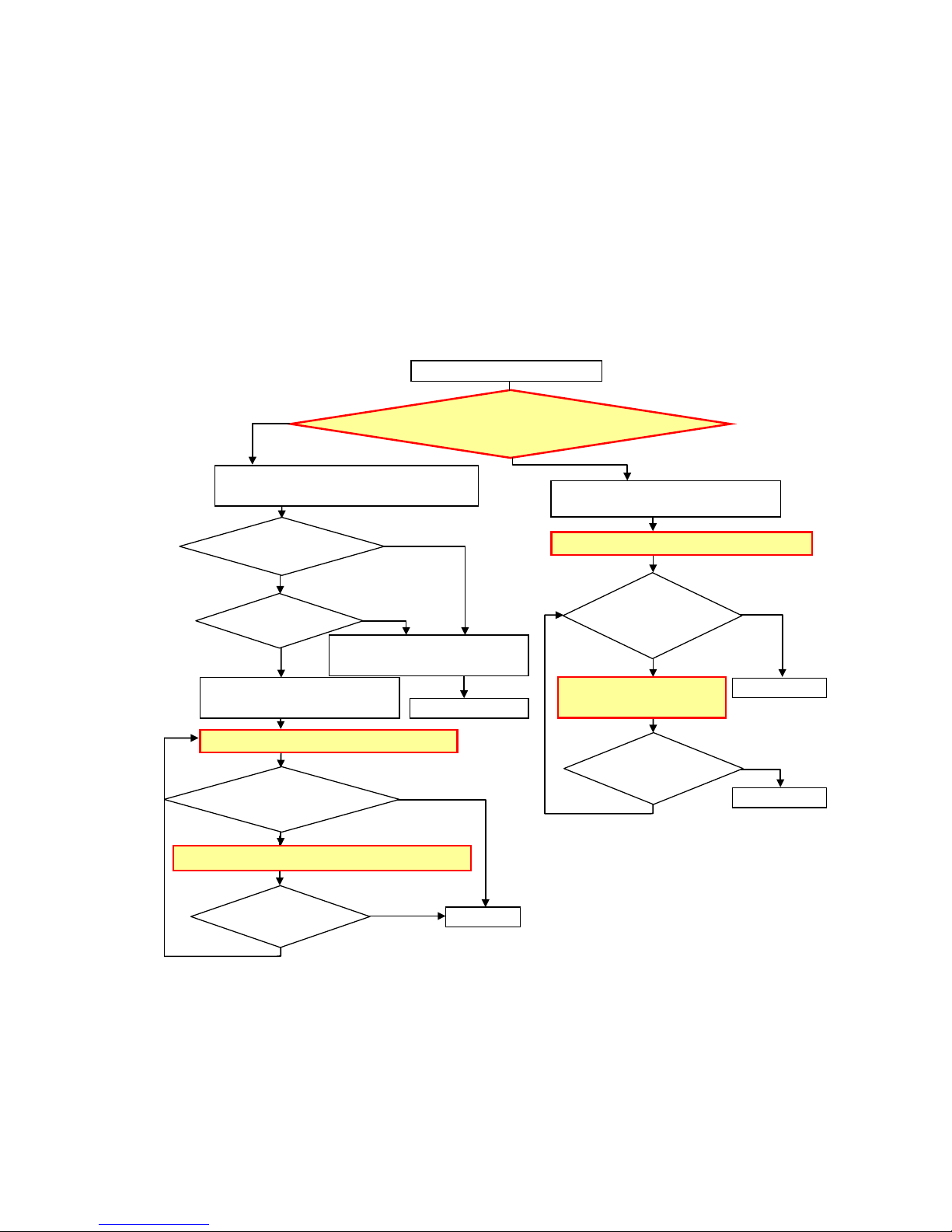
【How to check the unexecuted machine in the production line of the belt edge at failure】
C6600(Fuser Belt Rotation Error)/C6720(Fuser IH Belt
Rotation Error)/Fuser Belt Failure
<Flow chart>
No (A or later)
Yes
No
Whether the machine serial
number is less than A?
Yes
(Less than A)
Whether the fuser belt
edge was torn?
Adjust MOUNT FUSER JOINT using the tool.
Check Serial Number A of the main machine.
(Refer to the next page.)
Finish
Adjust MOUNT FUSER JOINT using the tool.
Finish
Flange key gets under the U-shape groov e of
the heat roller or is raised.
Yes
No
The fuser belt edge is torn.
Is the fuser belt edge
repeatedly torn after
adjustment?
Replace the fuser unit with “5” or later of
the last digit parts number.
Replace the fuser unit with “5” or
later of the last digit parts number.
Replace the fuser unit with “5” or
later of the last digit parts number.
Check the amount of the
fuser belt stepping aside.
Finish
No
No
Yes
Yes
Does the fuser belt shift
0.3mm or less?
Check the amount of the fuser belt stepping aside.
No
Yes
Does the fuser belt shift
0.3mm or less?
Is the fuser belt edge repeatedly
torn after adjustment?
Finish
(-->)
Yes
(-->) No
For 6500i/8000i
88
Page 89
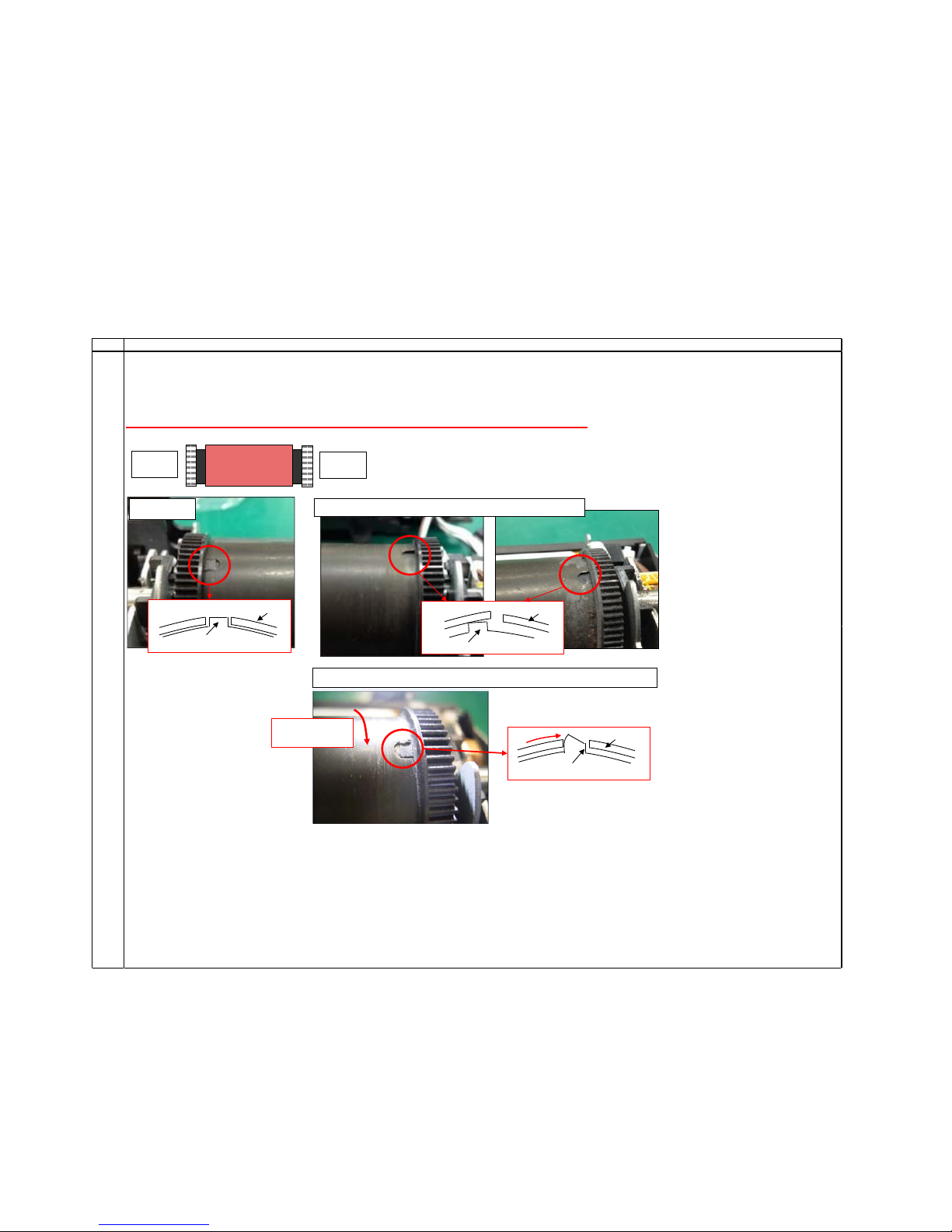
C6600(Fuser Belt Rotation Error)/C6720(Fuser IH Belt
Rotation Error)/Fuser Belt Failure
Step Checking contents
1
Detach the fuser unit and then check whether the flange keys of the machine front and rear side do not get under the inside heat roller and whether the flange key is
not raised due to being pressed by the heat roller.
(-->) (Note) Please shift the fuser belt aside when checking whether the flange keys do not get under the inside heat roller.
Please refer to Step 5 and 6 in Sheet 5) for details of the way to shift the fuser belt.
(Attention) If the heat roller is hot, please cover it with cloth instead of directly touching it by hand.
Machine
rear side
Normal
Flangekey
Heat roller
State that the flange key is r aised due to being pressed by the heat roller.
Rotating direction
of the heat roller
State that the flange key gets under the inside heat roller.
Machine
front side
Heat roller
Flangekey
Flangekey
Heat roller
For 6500i/8000i
89
Page 90
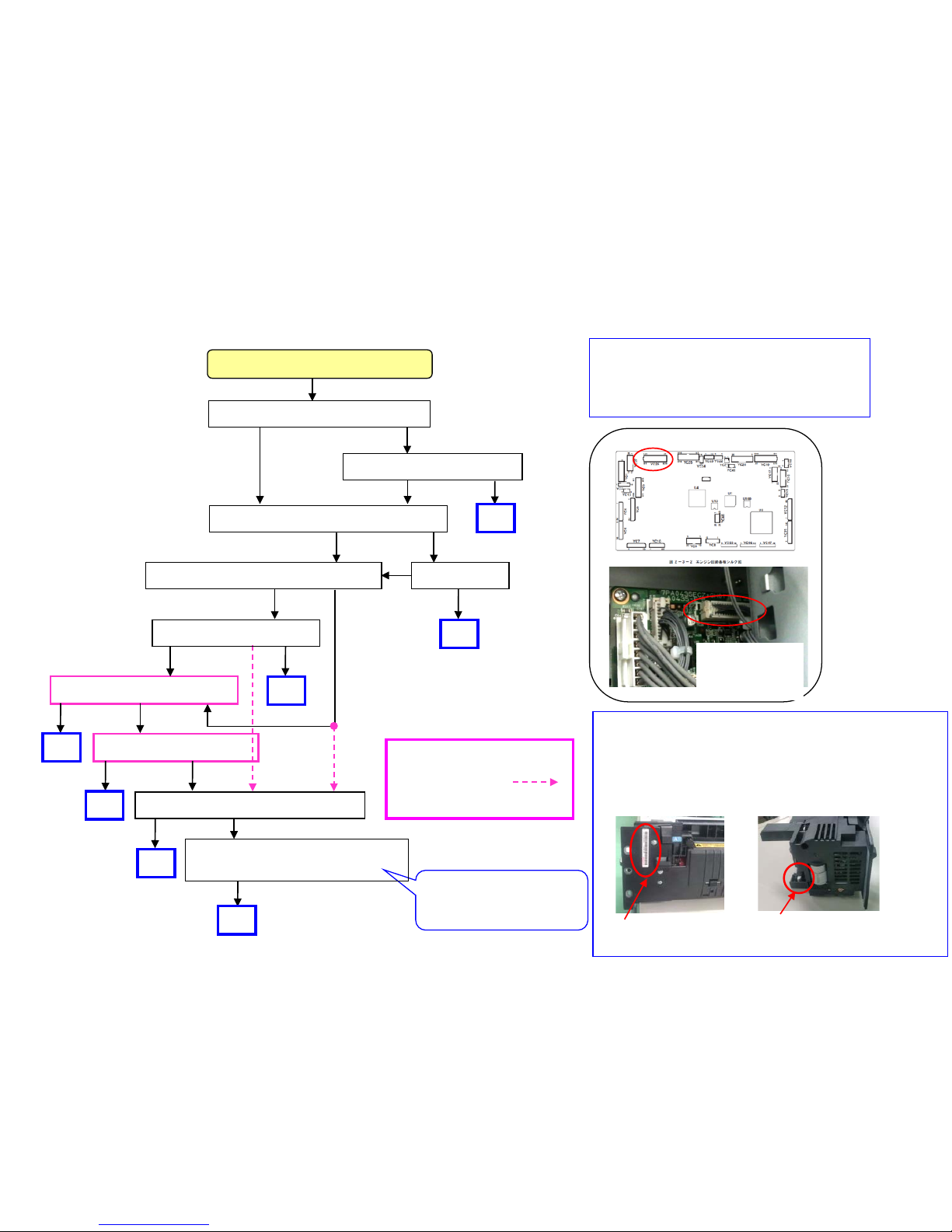
YC26(Engine PCB)
C6720 occurs
due to poor
connection
Identify the measured fuser unit (PI poor contact )
Method 1: Change “2” for part of serial no.
Method2:Even above number is 1, if the connector color
of PI is white on fuser unit, it has been modified.
White: Modified,
black: Not modified
KX8021X02529
Method1
Method2
Item code of harness
6550ci/7550ci :302LF46590
6500i/8000i :302K946590
Check firmware Ver (engine)
6550ci/7550ci : 2K9_1000.004.006
6500i/8000i : 2LF_1000.003.006
Whether it is after above version.
For C6600, IH PCB is not
necessary checked.
Check as referring to the
contents at left.
OK
OK
Check YC4 of IH PCB
NG
OK
OK
Replace the IH PCB
NG
OK
OK
NG
Replace the engine PCB
OK
OK
NG
Replace the harness between the
engine PCB and fuser unit.
OK
OK
C6600/C6720
Check firmware Ver.
OK
NG
NG
Check YC26 of Engine PCB
OK NG
Check the fuser unit (left lower fig.) Re-connect
Replace the fuser unit
NG OK
OK
OK
NG
Firmware Version Up
OK
NG
OK
C. Perform below checking.
C6600(Fuser Belt Rotation Error)/C6720(Fuser IH Belt
Rotation Error)/Fuser Belt Failure
For 6500i/8000i
90
Page 91
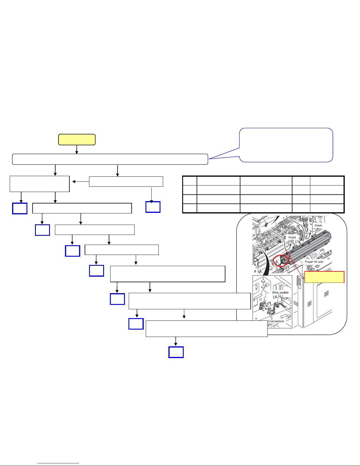
C6620(IH Core Motor rotation Error)
IH core motor
OK
Check whether updated with measured engine firmware. (refer to right Colum)
Install updated firmware
OK NG
OK NG
NG
OK
OK
OK
OK
Replace Exit PCB (only 6500i/8000i)
OK
OK
NG
OK
OK
NG
OK
NG
NG
Replace the Front PCB
OK
OK
NG
OK
OK
Replace the harness between the Front PCB and
Exit PCB(302LF46140)only 6500i/8000i
OK
Replace Engine PCB
Replace the harness between the Core Motor
and Exit PCB (302LF46100, 302K946140)
Replace the harness between the Front PCB and
Exit PCB(302LF46940,302K946080)
Replace IH unit.
Refer to Fig.1
Check the firmware version (engine)
6500i/8000i : 2LF_1000.003.006
No problem if it is after above version.
C6620
No. Item number Parts name Qt’y Remark
1 302K993150 FK-8709 IH 1 200Vspec
2 302K99C150 FK-8709 IH 1 China spec
3 302K99K150 FK-8709 IH 1 Korea spec
Fig.1
91
Page 92
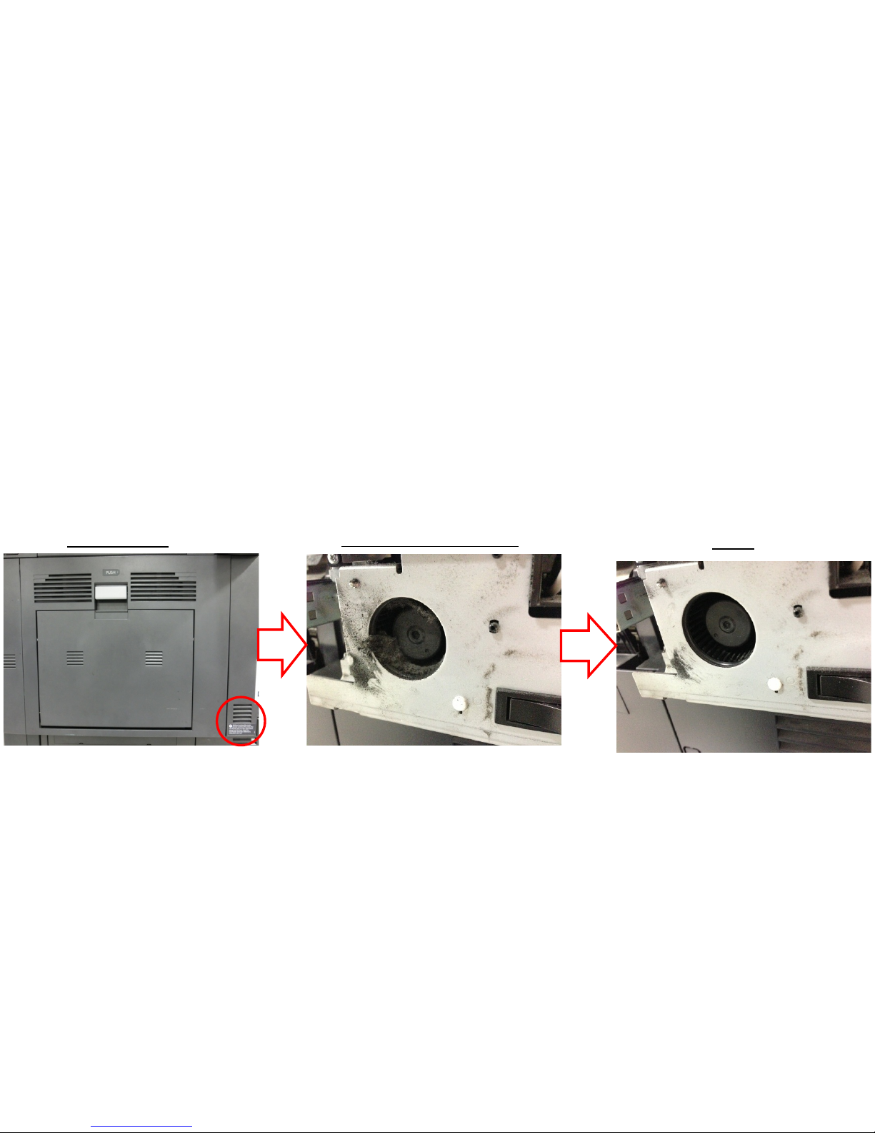
C6730
【Phenomenon】
Cooling fan of IHPWB is clogged by dust, cooling efficiency is reduced, C6730 (Fuser IH
substrate temperature error 1) is generated.
【How to Respond】
Clean the cooling fan with a vacuum cleaner.
After
Before (With clogging)
Fan Position
For 6500i/8000i
92
Page 93
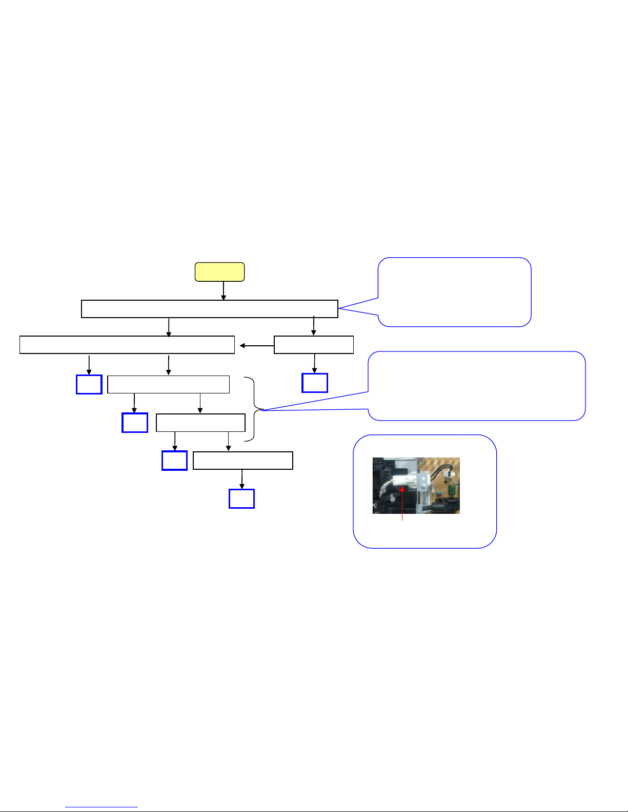
C6770( IH Fuser Low Power Error)
Check whether Engine firmware version is after the right Colum.
Replace Fuser unit.
NG
OK
OK
Replace IH PCB
NG
OK
OK
OK
OK
OK
Firmware Ver UP
NG
C6770
NG
Replace IH Coil Unit
OK
OK
Check connection of Fuser unit connector (right fig.)
OK
OK
NG
Check the firmware version (engine)
6500i/8000i : 2LF_1000.003.006
Increase withstanding of power noise.
If Fuser unit connector is
disconnected, C6770 occurs.
When C6770 occurs after cable of Fuser unit is
shorted and broken, while the fuser unit is kept
installing without replacing and replacing with new
IH PCB first, IH PCB will be damaged. So, replace
the IH PCB after replacing the Fuser unit.
Check the connector of Fuser Unit
93
Page 94
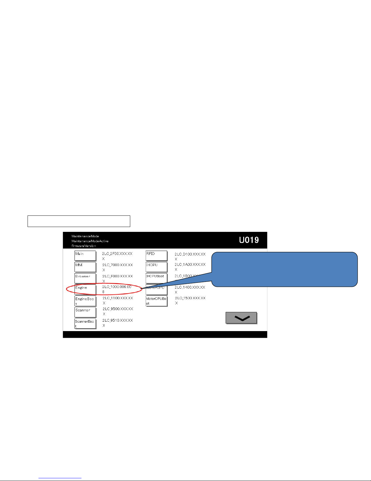
C6910(Engine Firmware Ready Error)
U019 firmware Version
C6910
Check the version of the firmware on the machine.
If the version is older than the following, upgrade the firmware to the latest version.
ENGINE
Venus :2LC_1000.007.0XX
Mercury :2K9_1000.005.0XX
Zeus/Gaia:2LF_1000.004.0XX
Check the Engine firmware
version by U019
94
Page 95
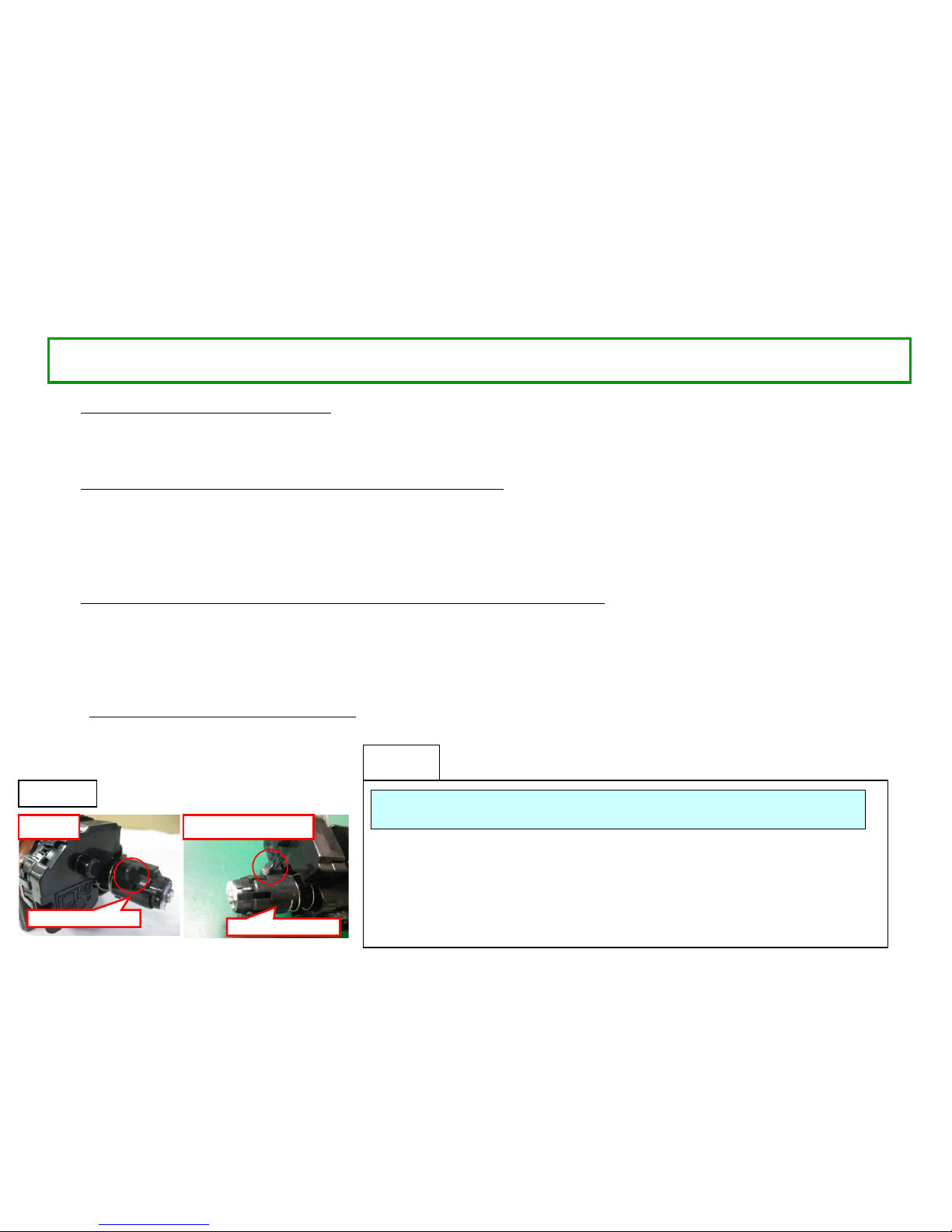
1.In case of abnormal sound occurs
a. Replace the DLP UNIT .
b. Re-assemble it as referring to below attention 1.
2. In case of no abnormal sound (developing driv e possible)
a. Check the firmware Ver.and version up with most updated one and
replace
the DLP UNIT .
b. Re-assemble it as referring to below attention 1.
3. In case of no abnormal sound and firmware vers ion is most updated one
a. Remove the INNER UNIT.
b. Check the CASS SHUTTER of the DLP U NI T.
c. If the parts is broken, replace the DLP UNIT.(Fig.1)
d. Re-assemble it as referring to below attention 1.
4. In case of not applicable above 1,2.3
a. It is possible of error at the DLP motor. Check the D LP motor.
C7101(Toner Control Sensor Error)
Normal Break (bend)
CASS SHUTTER
CASS SHUTTER
Fig.1
When pushing in the CASS LOCK release LEVER at the INNER UNIT, there is a
case not to push in smoothly .
In that case, without pushing in by force, re-install the INNER UNIT while shifting it
by right-hand side and fix.
If it pushes into INNER UNIT forcefully, the lock release cannot be done normally,
C2101, C7101, and unusual sound occur again and DLP UNIT may damage.
The measure against below condition was taken after 2011 Oct. production. Therefore,
below action is not necessary if the production month is O ct. and after.
attention 1
If the T/C control is not capable at the DLP or there is a possibility that DLP is LOCKing by jam in the developing powder outlet etc.
(It may be accompanied by the unusual rattling sound like no engagement of gears and C7101)
95
Page 96
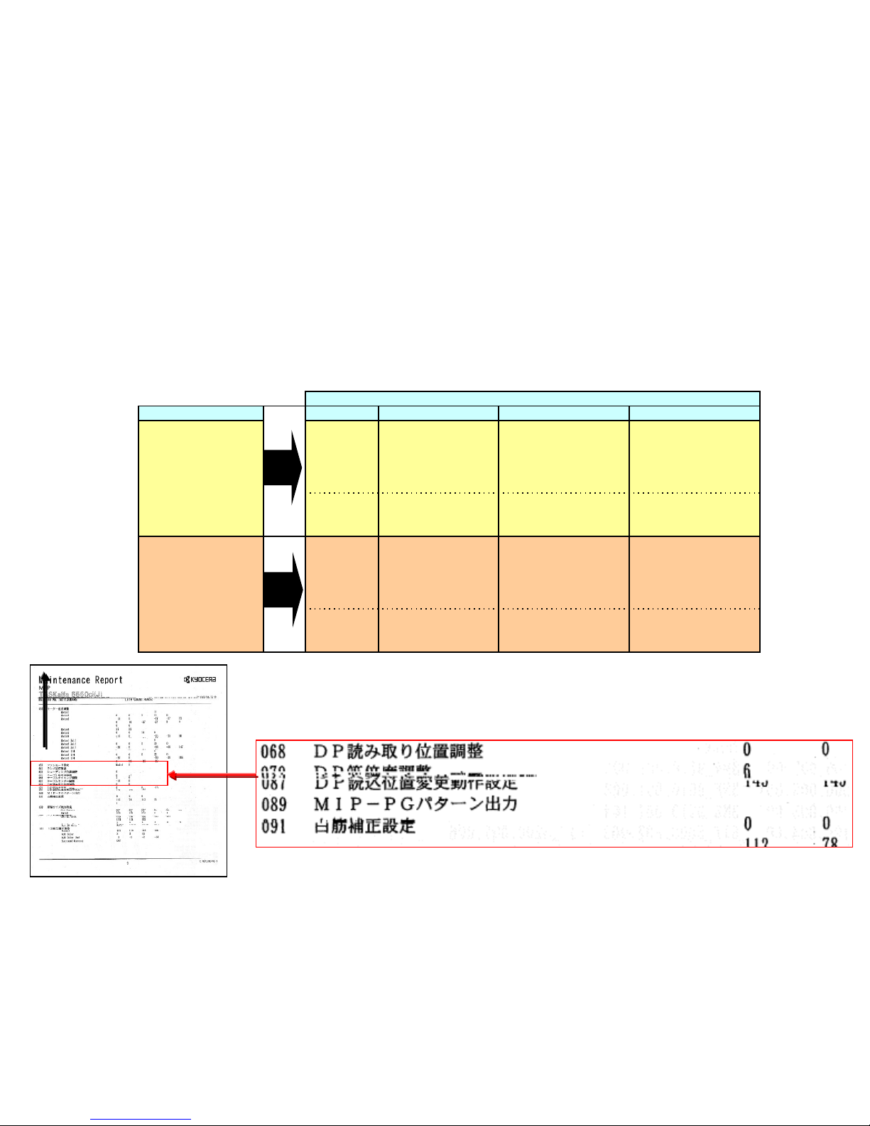
C9500/C9510/C9520/C0630/C0640/CF245
SATA cable contact failure
The SATA cable (No.1 to 4) may have contact failure or may be broken if the service call error below appears.
Perform the correctiv e ac ti on bel ow when it arises.
<Corrective acti on>
1) Check and perform t he cor r ect ive action for each checkpoint as described in the ser vice manual.
2) If the service call error still appears after the above action, the SATA cable may be broken and replace the
applicable cable.
[Image block dropout] (example)
Feed
direction
【Service bulletin】2LC-077(C103)
SATA cable to replace
Content of failure No Parts No. Parts name Affected model
- C9500 error
- C9510 error
- C9520 error
- C0630 error
- Scanned image
block dropout (Refer to
below for the image
sample)
1 302K946700* WIRE CCD DATA
5550ci/4550ci/3550ci/30
50ci
5500i/4500i/3500i
7550ci/6550ci
8000i/6500i
2 303M446020
WIRE INTERFACE
VIDEO
7550ci/6550ci,
8000i/6500i
DP-771
- C0640 error
- F245 error
3 302K946A20* WIRE HDD DATA1
5550ci/4550ci/3550ci/30
50ci
5500i/4500i/3500i
7550ci/6550ci
8000i/6500i
4 302K946A30* WIRE HDD DATA2
5550ci/4550ci
7550ci/6550ci
8000i/6500i
96
Page 97
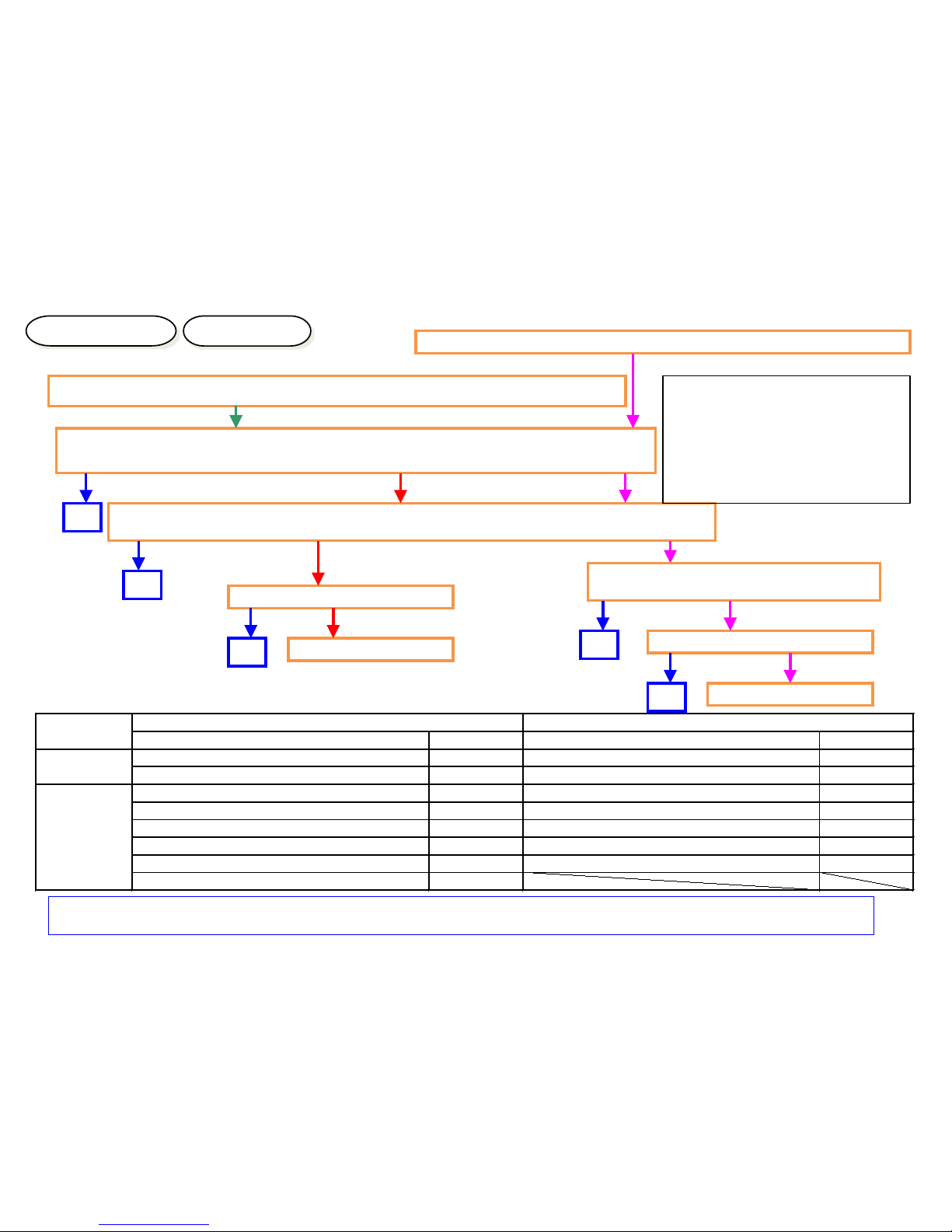
“Welcome” Screen Lock
Checking Method
Solution
Welcome Screen Lock ( The screen is not changed more than 3 and half min.)
Check the connection condition of harness and connector Betw een the Panel and
Main PCB, between Main PCB and HDD.
1.Check the contact of DDR memory (detach and attac h). (If possible, replac e it.)
1.Check the contact of CODE DIMM (detach and attach). (If possible, r eplace it.)
Replace Panel PCB
Replace Main PCB
OK
OK
<Connector Check Points>
(Between Main and Panel I/F)
Main PCB :YC12、YC17、YC30
Panel PCB:YC1、YC2、YC3
(Between Main and HDD)
Main PCB:YC1、YC2、YC27、YC32
OK
NG
NG
NG
<Note> At appearance of CF000, if Panel LED is “light up” as stating right, DDR2 failure might be the cause.
Check the contact between YS1 or YS2 and this DDR memory.
Memory LED Light Up
Attention LED Light Up
Welcome Screen Lock ( CF000 appears after 3 and half min.)
Replace Main PCB
Replace Panel PCB
OK
NG
NG
NG
NG
Check whether Panel Main PCB is
recovered by Boot mode.
OK
Product
Item Name Item Number Item Name Item Number
MAIN PCB PARTS PWB MAIN ASSY SP 302LH9414* PARTS PWB MAIN ASSY SP 302LF9417*
PARTS PWB MAIN ASSY SP EU 302LH9415* PARTS PWB MAIN ASSY SP EU 302LF9418*
PANEL PCB PARTS PWB PANEL MAIN ASSSY SP 302LC9425* PARTS PWB PANEL MAIN ASSSY SP 302K99484*
PARTS PWB PANEL MAIN ASSSY J SP 302LC9426* PARTS PWB PANEL MAIN ASSSY J SP 302K99485*
PARTS PWB PANEL MAIN ASSSY TW SP 302LC9456* PARTS PWB PANEL MAIN ASSSY TW SP 302K994B2*
PARTS PWB PANEL MAIN ASSSY CN SP 302LC9457* PARTS PWB PANEL MAIN ASSSY KR SP 302K994B4*
PARTS PWB PANEL MAIN ASSSY KR SP 302LC9458* PARTS PWB PANEL MAIN ASSSY KS SP 302K994B3*
PARTS PWB PANEL MAIN ASSSY KS SP 302LC9463*
3500i/4500i/5500i
6500i/8000i
97
Page 98
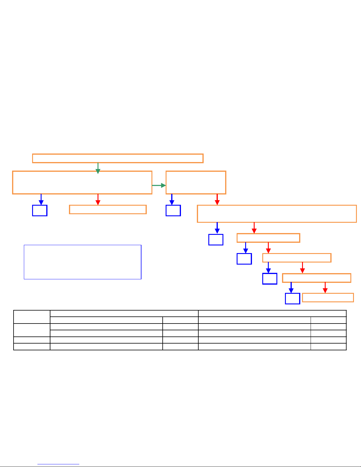
CF040(Communication Error between the Main
PCB and Engine PCB)
Whether aging dr i ve is starts or not after closing the cover.
Check the short cir cui t of harness for 5V or 3.3V
connected to the Engi ne PCB and recover the
fault wire.
Replace Engine PCB
Main PCB YC3
Re-insert the FFC
connector
Re-insert the Engine PCB FFC connector (YC46)
Replace FFC
Replace Main PCB
Replace Engine PCB
Replace HDD
OK OK
OK
OK
OK
OK
FFC item code:
5500i/4500i/3500i :
302K946A00 WIRE FFC MAIN-ENGINE
NG
NG
NG
NG
NG
NG
If CF040 occurs, take the following measure.
Product
Item Name Item Number Item Name Item Number
MAIN PCB PARTS PWB MAIN ASSY SP 302LH9414* PARTS PWB MAIN ASSY SP 302LF9417*
PARTS PWB MAIN ASSY SP EU 302LH9415* PARTS PWB MAIN ASSY SP EU 302LF9418*
ENGINE PCB PARTS PWB ENGINE ASSY SP 302LH9417* PARTS PWB ENGINE ASSY SP 302LF9420*
HDD PARTS STO RAGE DEVICE SP 302LH9307* PARTS STORAGE DEVICE SP 302LC9316*
3500i/4500i/5500i
6500i/8000i
98
Page 99
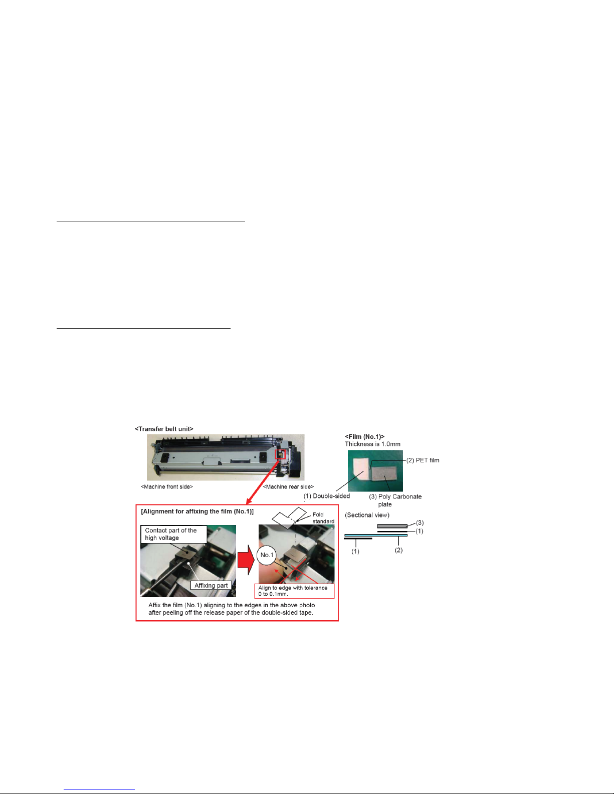
1. When CF182/CF186 occur after every printing.
1) Check connection of the harness (Engine - Main board) and connectors and check function.
*[Main⇔ENGINE Interface] Main board:YC3 Engine board:YC46 or YC50
2) Format the HDD and check function. (U024 FULL formatting)
3) Execute the U021 Memory initializing to initialize the controller backup memory and check function.
4) Replace the engine board and check function.
5) Replace the main board and check function.
6) Retrieve the USBLOG and contact the Service Administrative Division.
2.When CF182/CF186 occur from time to time
Add the film to the contact part of the high voltage terminal of the transfer belt unit.
*If the right cover isn’t closed sufficiently, the contact failure (leakage) may occur due to the wide gap between the high voltage
terminals at the right cover and the transfer belt. As the result, the F186 error may appear due to the misdetection of the inter-lock
switch caused by the noise that is generated by unstable transfer voltage.
Item :302LF22670 SHEET CONTACT TRANSFER 1set
CF182/CF186
【Service bulletin】2LH-0010(C128)
99
Page 100

a. Replace the DLP UNIT .
b. Re-assemble it as referring to below attention 1.
Abnormal Sound from Developing Section
When pushing in the CASS LOCK release LEVER at the INNER UNIT, there is a
case not to push in smoothly .
In that case, without pushing in by force, re-install the INNER UNIT while shifting it
by right-hand side and fix.
If it pushes into INNER UNIT forcefully, the lock release cannot be done normally,
C2101, C7101, and unusual sound occur again and DLP UNIT may damage.
The measure against below condition was taken after 2011 Oct. production. Therefore,
below action is not necessary if the production month is O ct. and after.
attention 1
There is a possibility that DLP is LOCKing by jam in the developing powder outlet etc.
(It may be accompanied by C2101 and C7101)
100
 Loading...