

Tascam IF-SM/DM Owner's Manual

This appliance has a serial number. Please
record the model number and serial number
and retain them for your records.
Model number
Serial number
»
IF-SM/DM
Surround Monitor Card
OWNER’S MANUAL
D00885000A

2 TASCAM IF-SM/DM Owner’s Manual
Contents
1 – Introduction
Installation ............................................ 3
Connections ........................................... 4
Monitor alignment ............................... 4
2 – Using the card
OPERATION option ............................... 5
Muting channels ............................ 5
Soloing channels ............................ 6
Downmix on/off ............................ 6
Bass management ......................... 6
Alternative speakers ..................... 6
Oscillator routing ........................... 6
To 2.1 ............................................. 6
SPL reference and level ................. 6
Notes on other hardware controls ...6
ROUTING option ................................... 7
Monitoring keys ............................ 7
Output routing .............................. 7
DOWNMIX option .................................8
6.1 format ....................................... 9
5.1 format ..................................... 10
LRCS format ................................. 11
Stereo format ............................... 12
BASS MANAGEMENT option .............. 13
Type 1 bass management ........... 13
Type 2 bass management ........... 13
MONITOR ALIGNMENT option ........... 14
Trimming the levels ..................... 14
Generating the pink noise .......... 15
Setting the surround speaker level ...15
Adjusting the LFE GAIN ............... 15
Channel delay .............................. 15
Setting the overall surround level ... 16
3 – Reference
Block diagram ...................................... 17
Level diagram ......................................18
Audio performance .............................18
Table of figures
Figure 1.1: Fitting the card . . . . . . . . . . . . . . . . . . . . . . . . . . . . . . . . . . . . . . . . . . . . . . . . . . . . . 3
Table 1.2: Pin assignments of the IF-SM/DM analog outputs . . . . . . . . . . . . . . . . . . . . . . . . . . 4
Figure 2.1: The main surround monitor screen . . . . . . . . . . . . . . . . . . . . . . . . . . . . . . . . . . . . . 5
Figure 2.2: The OPERATION option . . . . . . . . . . . . . . . . . . . . . . . . . . . . . . . . . . . . . . . . . . . . . . . 5
Figure 2.3: SHIFTed number keys used for channel control . . . . . . . . . . . . . . . . . . . . . . . . . . . 5
Figure 2.4: ROUTING option screen . . . . . . . . . . . . . . . . . . . . . . . . . . . . . . . . . . . . . . . . . . . . . . 7
Figure 2.5: Example downmix screen showing attenuation points . . . . . . . . . . . . . . . . . . . . . 8
Table 2.6: 6.1 to 5.1 downmix pattern . . . . . . . . . . . . . . . . . . . . . . . . . . . . . . . . . . . . . . . . . . . . 9
Table 2.7: 6.1 to 2.1 downmix pattern . . . . . . . . . . . . . . . . . . . . . . . . . . . . . . . . . . . . . . . . . . . . 9
Table 2.8: 6.1 to stereo downmix pattern . . . . . . . . . . . . . . . . . . . . . . . . . . . . . . . . . . . . . . . . . 9
Table 2.9: 6.1 to mono downmix pattern . . . . . . . . . . . . . . . . . . . . . . . . . . . . . . . . . . . . . . . . . . 9
Table 2.10: 5.1 to phantom rear LRCS downmix pattern . . . . . . . . . . . . . . . . . . . . . . . . . . . . 10
Table 2.11: 5.1 to hard rear LRCS downmix pattern . . . . . . . . . . . . . . . . . . . . . . . . . . . . . . . . 10
Table 2.12: 5.1 to 2.1 . . . . . . . . . . . . . . . . . . . . . . . . . . . . . . . . . . . . . . . . . . . . . . . . . . . . . . . . . 10
Table 2.13: 5.1 to stereo downmix pattern . . . . . . . . . . . . . . . . . . . . . . . . . . . . . . . . . . . . . . . 10
Table 2.14: 5.1 to mono downmix pattern . . . . . . . . . . . . . . . . . . . . . . . . . . . . . . . . . . . . . . . . 11
Table 2.15: LRCS to stereo downmix pattern . . . . . . . . . . . . . . . . . . . . . . . . . . . . . . . . . . . . . . 11
Table 2.16: LRCS to mono downmix pattern . . . . . . . . . . . . . . . . . . . . . . . . . . . . . . . . . . . . . . 12
Table 2.17: LRCS to LRCS with phantom rear downmix pattern . . . . . . . . . . . . . . . . . . . . . . 12
Figure 2.18: Stereo to mono downmix . . . . . . . . . . . . . . . . . . . . . . . . . . . . . . . . . . . . . . . . . . . 12
Figure 2.19: Example downmix screen showing attenuation points . . . . . . . . . . . . . . . . . . . 13
Figure 2.20: Type 1 and Type 2 bass management for 5.1 and 6.1 settings . . . . . . . . . . . . . 13
Figure 2.21: Example downmix screen showing attenuation points . . . . . . . . . . . . . . . . . . . 14
Figure 3.1: Block diagram . . . . . . . . . . . . . . . . . . . . . . . . . . . . . . . . . . . . . . . . . . . . . . . . . . . . . 17
Figure 3.2: Level diagram . . . . . . . . . . . . . . . . . . . . . . . . . . . . . . . . . . . . . . . . . . . . . . . . . . . . . 18
TASCAM IF-SM/DM Owner’s Manual 3
1 – Introduction
The IF-SM/DM card allows the connection of one or two surround monitoring systems. It provides flexible setup capabilities, routing, downmix capabilities, bass management, and monitor
setup, etc. from within the IF-SM/DM’s interface.
Installation
You should not install or remove cards yourself, but should refer installation to a qualified
TASCAM distributor. Otherwise, the warranty will be voided.
1Turn off the main unit and disconnect
it from the power supply. Disconnect
all other equipment connected to it.
WARNING
The above step is most important. If you do not
do this, there is a risk that you may cause damage
to the main unit as well as to other equipment.
2 Use a screwdriver to remove the blank-
ing panel from the slot into which you
will fit the interface card. Keep the
retaining screws in a safe place.
If you are installing more than one
card, we suggest that you start from the
top slot (slot 1) and work downwards.
Take care, if you are removing a previously-fitted interface card, that you
are removing the retaining screws, and
not the smaller screws which fix the
card to the rear plate. Also, if you are
removing a previously-fitted card, use
the binding posts on the rear plate to
help remove the card.
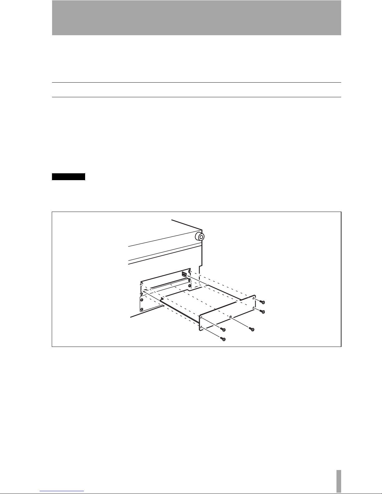
3 Remove the interface card from the
anti-static protective bag. Hold the
card by the edges, and insert it, component side upwards, into the slot.
Insert the card between the guide rails
and slide it all the way into the slot, as
shown. You may have to push firmly to
plug the card into the internal connector.
4 Locate the card into the connector
inside the main unit. Push the card
firmly, without forcing, so that the connector grips the end of the card.
Figure 1.1: Fitting the card

1 – Introduction : Connections
4 TASCAM IF-SM/DM Owner’s Manual
A new unit’s card slot and/or new card
may be a little stiff. Make sure that the
card is pushed as far as it will go (so
that the card rear connector plate
touches the rear panel of the unit).
5 Use the screws supplied with the card
to attach the rear panel of the interface
card to the rear panel of the unit.
6 Repeat the installation process for all
the interface cards that you are fitting.
• When removing a card, unscrew the
five retaining screws and use the “pull
posts” on the rear panel of the card to
remove it from the unit. There are no
rules governing which interface cards
may be fitted in any of the slots, except
for the IF-FW card, which must be fitted in slot 1—any other interface card
may be fitted in any expansion slot.
Connections
The D-sub 25-pin connector allows the connection of up to eight balanced analog connections
at +4dBu levels (the impedance is 100Ω).
Suitable cables can be obtained from most
professional audio suppliers.
Monitor alignment
The card allows each channel to have an individual delay time set in milliseconds, as well
as a trim level.
This is set using the
MONITOR ALIGNMENT
screen, and the procedure is described later in
this manual (“MONITOR ALIGNMENT
option” on page 14).
The overall SPL level can be set (on the
OPER-
ATION screen), along with the LFE gain.
Pin 1 2 3 4 5 6 7 8 9 10 11 12 13‘
Signal
8+ 8Gnd 7– 6+ 6Gnd 5– 4+ 4Gnd 3– 2+ 2Gnd 1– NC
8– 7+ 7Gnd 6– 5+ 5Gnd 4– 3+ 3Gnd 2– 1+ 1Gnd
Pin 14 15 16 17 18 19 20 21 22 23 24 25
Table 1.2: Pin assignments of the IF-SM/DM analog outputs
TASCAM IF-SM/DM Owner’s Manual 5
2 – Using the card
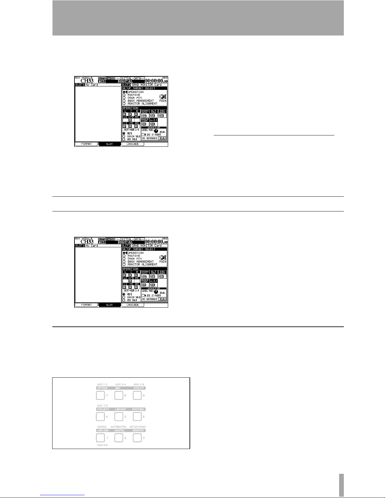
You can access the card’s functions by pressing the
DIGITAL key and selecting the SLOT
sub-screen.
Figure 2.1: The main surround monitor screen
The surround monitor card is here shown
installed in slot 2.
The top half of this part of the screen shows
the different options (referred to as
SETUP TAR-
GETs), and the lower half shows the settings
for these options.
Use the POD 4 encoder
1
to highlight the dif-
ferent options available, and the
ENTER key
to select the option.
OPERATION option
The OPERATION option allows the following
operations to be carried out:
Figure 2.2: The OPERATION option
• Muting of individual channels
• Soloing (exclusive or mixed) of individual
channels
• Switching downmix on and off
• Switching alternative speakers on and off
• Routing the internal oscillator on and off
•Turning bass management on and off
• Instant downmix to a 2.1 setting
• Setting the monitoring level
• Setting SPL reference level
Muting channels
Use the cursor and ENTER keys to select the
MUTE option. Mute the monitoring of individ-
ual channels using the
SHIFTed number keys
as described here:
When a channel is muted, it appears with an
inverse
M on the display. Unmuted channels
show an on-screen “button”.
Note that you can also use the cursor and
ENTER keys to change the mute status.
1. Throughout this manual, we assume that
the card is fitted in slot 2. If the card is fitted in slot 1, any reference to POD 4
should be interpreted as referring to POD
2, and any reference to POD 3 should be
interpreted as referring to POD 1.
Figure 2.3: SHIFTed number keys used for channel control
LCR
LC LFE RC
LS CS RS

2 – Using the card : OPERATION option
6 TASCAM IF-SM/DM Owner’s Manual
Soloing channels
This works with the same SHIFTed number
keys as for muting (see Figure 2.3, SHIFTed
number keys used for channel control) as well
as the cursor and
ENTER key options.
There are two solo options—one for an exclusive solo mode, where only one channel at a
time is active, and one for a mixed solo mode,
where selected channels are active.
The on-screen solo marks are shown by an S
button, in the same way as the mute buttons are
shown by an
M (they invert when active, etc.).
Downmix on/off
Use the on-screen DOWN MIX button to turn
downmixing on and off (as set up in the
DOWN
MIX option) — ignored when the alternative
speaker switch, 2.1 switch or oscillator switch
are on.
Bass management
Use the on-screen BASS MGT button to turn
bass management on and off (as set up in the
BASS MANAGEMENT option) — ignored when
the alternative speaker switch, 2.1 switch or
oscillator switch are on.
Alternative speakers
This routes the signal when downmixed to
stereo, to the speakers connected to the LC
and RC channels, which are not used in the
surround patterns.
This allows the use of a pair of “large” stereo
speakers together with smaller surround monitors, without the need for repatching.
Naturally, downmix is not possible with this
switch on.
Oscillator routing
Allows the routing of the mixer’s internal
oscillator to the surround card outputs.
When the oscillator is routed in this way, soloing is automatically changed to exclusive
soloing (it reverts to the previous setting when
the oscillator is not routed in this way).
Note that downmix and bass management are
not available when the oscillator is routed in
this way.
To 2.1
When on and the current surround mode is 5.1
or 6.1, this setting automatically overrides the
current downmix setting (of course, downmix
is not possible when this switch is on).
When this setting is deactivated, the original
downmix and mode are restored, as is the
mute status of the LFE channel.
USE ST-FADER
If you check “USE ST-FADER”, you can adjust
the Monitor level settings by the Stereo fader.
SPL reference and level
Note that the SPL REFERENCE setting and monitor level settings are made on this page. These
are explained further in “MONITOR ALIGNMENT option” on page 14.
 Loading...