

Page 1

Bi-directional Power
Sensor 2 Series
User Manual
Document #: 050-015-0070
Revision: 02
October 2011
TASC Systems Inc. •••• Langley, BC •••• Canada
Page 2

Bi-directional Power Sensor 2 Series User Manual 050-015-0070R02
Disclaimer
TASC Systems Inc. will not be held responsible for any damages, direct or indirect,
arising from the use of our materials or from any other causes. Any liability
whatsoever is hereby expressly limited to replacement or repair of defective
materials.
This manual contains proprietary information that is the intellectual property of TASC
Systems Inc. Reproduction, disclosure, modification or distribution, wholly or in part,
without prior written permission from TASC Systems Inc., is strictly prohibited.
TASC Systems Inc. is continuously working to improve system performance and
expand product capabilities. Specifications and features contained within this
document are subject to change without notice.
For additional copies of this publication contact:
TASC Systems Inc
.
Tel 604-455-2000
9415 – 202 Street Fax 604-888-9712
Langley, BC V1M 4B5 [email protected]
Canada www.tascsystems.com
Copyright 2002-2011 TASC Systems Inc., Langley, BC Canada
TASC Systems Inc. All Rights Reserved. Page 2
Page 3

Bi-directional Power Sensor 2 Series User Manual 050-015-0070R02
PREFACE
This document describes the installation, configuration and operation of TASC
Systems’ Bi-directional Power Sensor 2 Series.
Hardware described in this document is subject to ongoing development and
improvement. Consequently there may be minor discrepancies between the
information in this document and the performance and design of the hardware.
Before connecting any equipment to the Bi-directional Power Sensor 2 Series
(BPS 2 Series) the user is advised to read this document in its entirety.
Application of voltages in excess of the built-in protection could seriously
damage the BPS 2 Series and/or the equipment it is connected to.
TASC Systems Inc. All Rights Reserved. Page 3
Page 4

CONTENTS
Bi-directional Power Sensor 2 Series User Manual 050-015-0070R02
PREFACE ........................................................................................................................................................... 3
CONTENTS ........................................................................................................................................................ 4
REVISION HISTORY.......................................................................................................................................... 5
RELATED DOCUMENTS .................................................................................................................................. 6
1.
PRODUCT OVERVIEW ........................................................................................................................... 7
1.1. AOUT ............................................................................................................................................ 8
1.2. GND .............................................................................................................................................. 8
1.3. VDC ............................................................................................................................................... 8
1.4. DOUT ............................................................................................................................................ 8
2.
INSTALLATION AND SETUP ................................................................................................................. 9
2.1. BPS 2 Series stand alone ........................................................................................................... 9
2.2. BPS 2 Series 19” Rack ............................................................................................................. 10
3.
CALIBRATION TABLES ....................................................................................................................... 13
3.1. 160 MHz ...................................................................................................................................... 13
3.2. 450 MHz ...................................................................................................................................... 14
TASC Systems Inc. All Rights Reserved. Page 4
Page 5

REVISION HISTORY
Revision
Date
Changes
Bi-directional Power Sensor 2 Series User Manual 050-015-0070R02
R00 July 2010
R01 August 2011
R02 October 2011
• Original Document
• Added BPS 2 Series DB15 Interface Table
• Added 450Mhz Calibration table
• Updated 160MHz and 450MHz Calibration
tables
TASC Systems Inc. All Rights Reserved. Page 5
Page 6

Bi-directional Power Sensor 2 Series User Manual 050-015-0070R02
RELATED DOCUMENTS
• SCCU siteCOMMANDER/RSM Configuration Utility User Manual (050-015-0055)
• siteVIEW 2.0 User Manual (050-015-0050)
• siteCOMMANDER User Manual (015-050-0002)
• siteRSM User Manual (015-050-0052)
TASC Systems Inc. All Rights Reserved. Page 6
Page 7
Bi-directional Power Sensor 2 Series User Manual 050-015-0070R02
1. PRODUCT OVERVIEW
The TASC Bi-directional Power Sensor 2 Series (BPS 2 Series) is a commercial grade device for
monitoring forward and reflected power from a radio through a transmission line, to an antenna.
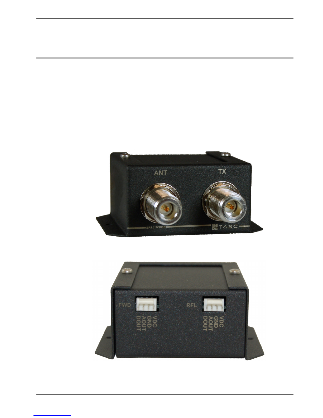
The BPS 2 Series is equipped with 2 female N-Type connectors, the Input (TX) connector should
be connected to the BTS TX or TX/RX output at a point where the device has a good “view” of
the antenna and the transmission line. The Output (ANT) connector should be connected to the
transmission line attached to the antenna.
A 4 pin key lock connector provides the analog level out, power and ground which is wired to a
TASC site monitoring device such as the siteCOMMANDER or siteRSM.
There is one connector per side (forward and reflected).
Figure 1 – Bi-directional Power Sensor 2 Series
TASC Systems Inc. All Rights Reserved. Page 7
Page 8

1.1. AOUT
The AOUT output connects to one of the analog inputs of the TASC’s site monitoring
devices (siteRSM or siteCOMMANDER). siteVIEW 2.0 and SCCU software provide the
GUI used to monitor and set-up the alarm points for the forward and reflected power
levels.
siteVIEW 2.0 provides a formula field to convert the analog level (VDC) into power (dBm
or Watts).
The BPS 2 Series must be set for the 0-5VDC analog range to operate correctly. Please
refer to the siteCOMMANDER (015-050-0002) or siteRSM User Manual (015-050-0052)
for instructions.
Bi-directional Power Sensor 2 Series User Manual 050-015-0070R02
If a formula is required in the 40-2000Mhz range that is not in the appendix,
please contact TASC Systems Inc for assistance.
1.2. GND
The GND pin should be connected to the system ground.
1.3. VDC
The VDC pin requires 6-26 VDC applied to its input.
1.4. DOUT
The DOUT pin provides an open-drain output that latches low when the TX or ANT input
levels drop below a factory set threshold.
Voltages in excess of +26VDC will cause irreparable damage to the board.
Please make sure that the 4pin press lock connector is properly seated before
applying power.
TASC Systems Inc. All Rights Reserved Page 8
Page 9

Bi-directional Power Sensor 2 Series User Manual 050-015-0070R02
2. INSTALLATION AND SETUP
These sections provide the necessary information to install the BPS 2 Series. The BPS 2 Series
provides both forward and reflected power readings in the form of analog levels back to the
TASC siteVIEW 2.0 software using the TASC siteRSM or siteCOMMANDER monitoring devices.
There are two ways to install the BPS 2 Series, one way is stand alone interfacing directly to a
siteRSM or siteCOMMANDER, the second way is via the 19” rack configuration to a siteRSM
1RU or 2RU chassis via a D-Sub ribbon cable.
2.1. BPS 2 Series stand alone
The stand alone configuration connects the AOUT (RFL) and AOUT (FWD) directly to the
TASC site monitoring products without the 19” rack.
In this configuration it is up to the user to extend the provided cable length to fit the
application. Simply cut one end of the provided cable and strip the leads and screw them
down to the analog input on the site monitoring device.
Wire Connections:
BPS 2 Series Cable Connections (RFL & FWD)
Legend Function
AOUT
GND Ground
VDC 7-20 VDC power input
DOUT
Analog level to site
monitor analog input
Low power output to
digital input on site
monitor
TASC Systems Inc. All Rights Reserved Page 9
Page 10
Bi-directional Power Sensor 2 Series User Manual 050-015-0070R02
2.2. BPS 2 Series 19” Rack
The 19” rack mount configuration allows for easy installation of up to 4 BPS 2 Series units
to one siteRSM 19” 1 or 2 RU rack. The rack mount configuration is equipped with a
Female DB-15, 8 port interface board for easy integration.
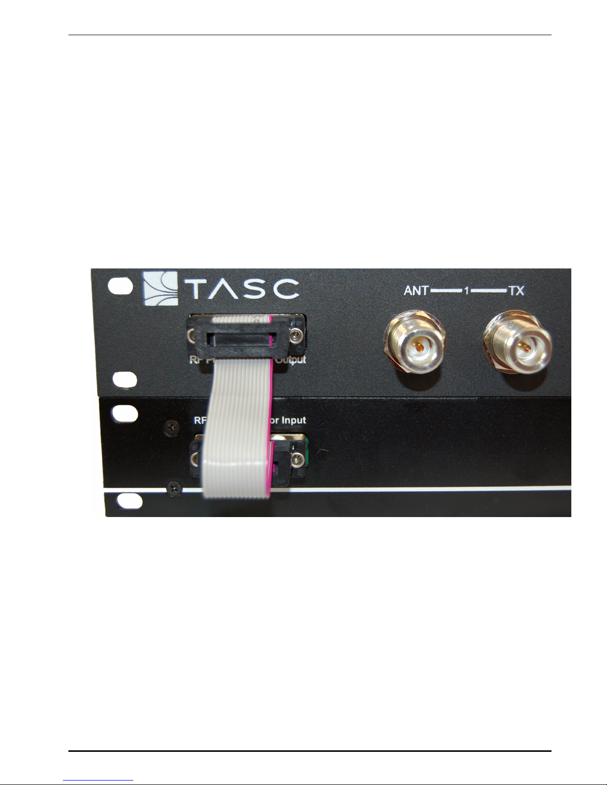
The provided DB-15 ribbon cable interfaces the RF Power Monitor Output to the siteRSM
19” rack RF Power Monitor Input. See the image below.
Figure 2 – BPS Rack Configuration to siteRSM
TASC Systems Inc. All Rights Reserved Page 10
Page 11
Bi-directional Power Sensor 2 Series User Manual 050-015-0070R02
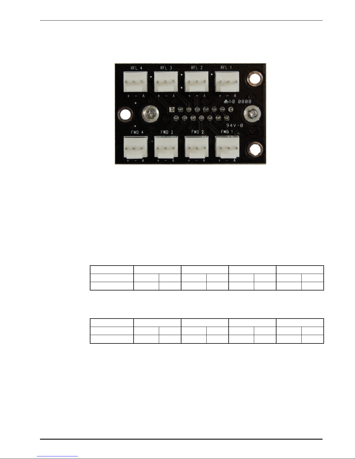
When installing a new BPS to the 19” rack, the interface board consists of 4 RFL
(Reflected) connectors on the top portion of the board and 4 FWD (Forward) connectors
on the bottom as seen in the below image.
Figure 3 – RF Power Monitor Interface Board
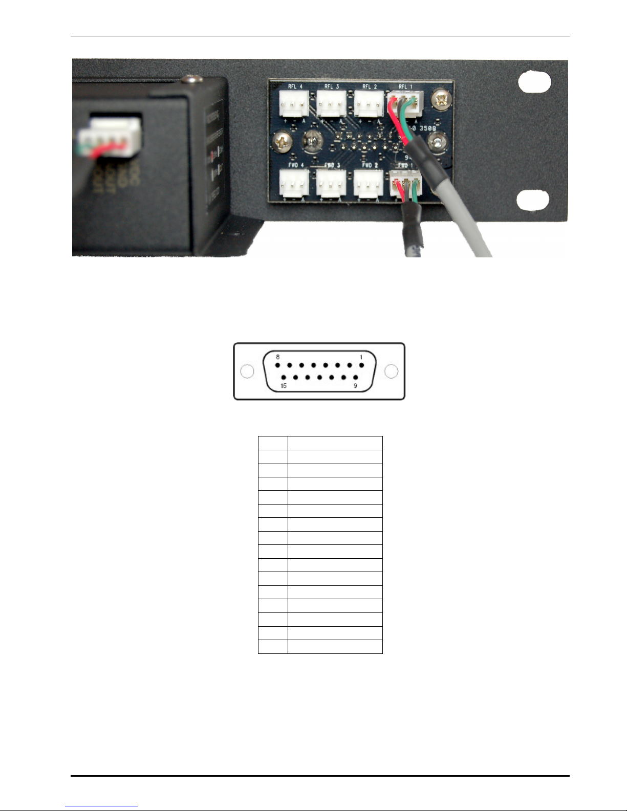
Simply match the RFL cable on the BPS 2 Series to the RFL connector and the FWD
cable on the BPS 2 Series to the FWD connector on the board. The image below shows
how to interface one (1) BPS 2 Series to the interface board using the outside most
connectors first, RFL 1 and FWD 1.
If only one Analog Input Expansion is installed, range 9 - 16 will be used to
monitor BPS 2 Series input power. The channel allocation will be:
BPS1 BPS2 BPS3 BPS4
Analog Inputs 9 10 11 12 13 14 15 16
DB15 Interface FWD1 RFL1 FWD2 RFL2 FWD3 RFL3 FWD4 RFL4
If the manufacturer installed both Analog Input Expansion and BPS Input Expansion,
range 17 – 24 will be used to monitor BPS Input Power:
BPS1 BPS2 BPS3 BPS4
Analog Inputs 17 18 19 20 21 22 23 24
DB15 Interface FWD1 RFL1 FWD2 RFL2 FWD3 RFL3 FWD4 RFL4
TASC Systems Inc. All Rights Reserved Page 11
Page 12
Bi-directional Power Sensor 2 Series User Manual 050-015-0070R02
Figure 4 – Single BPS Connection
If using the 19” rack BPS with the siteCOMMANDER configuration, an interface cable will
need to be created between the rack and the siteCOMMANDER analog inputs. Listed
below is the pin out of the DB-15 RF Power Monitor Output connector.
Pin Description
1 RFL 4
2 GND
3 RFL 3
4 RFL 2
5 GND
6 RFL 1
7 VDC + (6-26VDC)
8 Not Used
9 FWD 4
10 FWD 3
11 GND
12 FWD 2
13 FWD 1
14 GND
15 GND
Please refer to the Related Documents section of this manual for information regarding
physical configuration of the analog input jumpers of the siteCOMMANDER or siteRSM to
accept a BPS 2 Series as well, please refer to the SCCU or siteVIEW 2.0 Software
Manuals for information regarding software configuration of the analog inputs.
TASC Systems Inc. All Rights Reserved Page 12
Page 13
Bi-directional Power Sensor 2 Series User Manual 050-015-0070R02
3. CALIBRATION TABLES
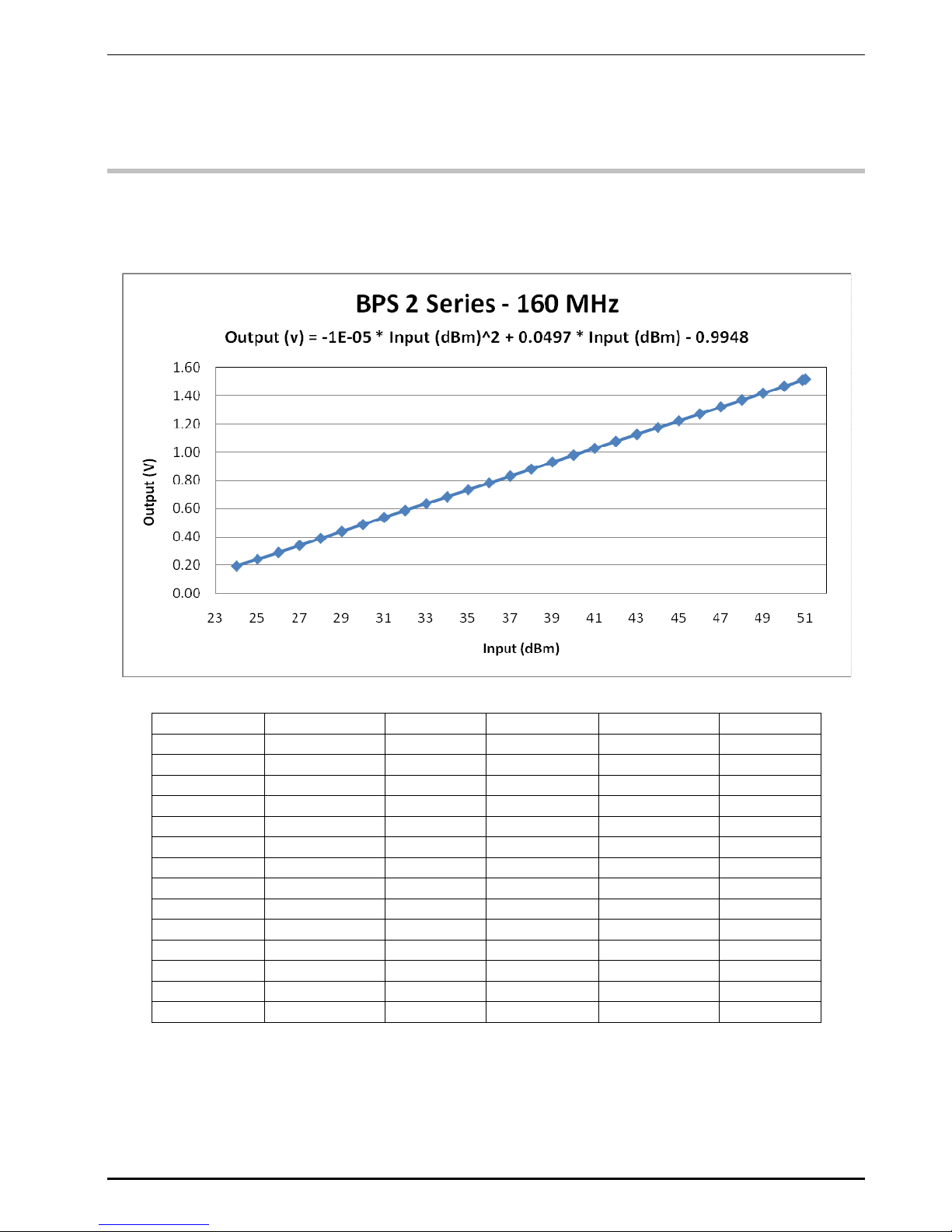
3.1. 160 MHz
Input (dBm) Input (Watts) Output (V) Input (dBm) Input (Watts) Output (V)
24 0.25 0.19 38 6.31 0.88
25 0.32 0.24 39 7.94 0.93
26 0.40 0.29 40 10.00 0.98
27 0.50 0.34 41 12.59 1.03
28 0.63 0.39 42 15.85 1.07
29 0.79 0.44 43 19.95 1.12
30 1.00 0.49 44 25.12 1.17
31 1.26 0.54 45 31.62 1.22
32 1.58 0.59 46 39.81 1.27
33 2.00 0.63 47 50.12 1.32
34 2.51 0.68 48 63.10 1.37
35 3.16 0.73 49 79.43 1.42
36 3.98 0.78 50 100.00 1.47
37 5.01 0.83 51 125.89 1.51
In siteVIEW, enter the following formula to convert the analog voltage to dBm:
(20.131*X^6-112.74*X^5) + (260.37*X^4-315.65*X^3)+(209.34*X^2-50.197*X)+29.295 (see
siteVIEW manual in regards to entering formulas).
TASC Systems Inc. All Rights Reserved Page 13
Page 14
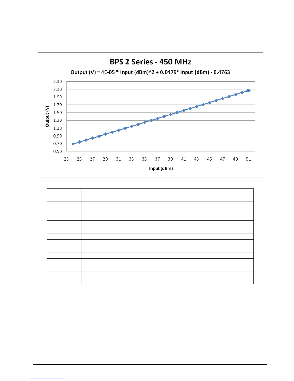
3.2. 450 MHz
Bi-directional Power Sensor 2 Series User Manual 050-015-0070R02
Input (dBm) Input (Watts) Output (V) Input (dBm) Input (Watts) Output (V)
24 0.25 0.70 38 6.31 1.40
25 0.32 0.75 39 7.94 1.45
26 0.40 0.80 40 10.00 1.50
27 0.50 0.85 41 12.59 1.55
28 0.63 0.90 42 15.85 1.61
29 0.79 0.95 43 19.95 1.66
30 1.00 1.00 44 25.12 1.71
31 1.26 1.05 45 31.62 1.76
32 1.58 1.10 46 39.81 1.81
33 2.00 1.15 47 50.12 1.86
34 2.51 1.20 48 63.10 1.92
35 3.16 1.25 49 79.43 1.97
36 3.98 1.30 50 100.00 2.02
37 5.01 1.35 51 125.89 2.07
In siteVIEW, enter the following formula to convert the analog voltage to dBm:
(2.0275*X^6-14.14*X^5)+(39.384*X^4-56.0938*X^3)+(42.955*X^2+3.31688*X)+12.665 (see siteVIEW
manual in regards to entering formulas).
TASC Systems Inc. All Rights Reserved Page 14
 Loading...