


Instruction Manual
TM
D103666X012
January 2015 - Rev. 00
Relief Valves
SUMMARY
Introduction ........................................................................ 1
SEP Statement .................................................................. 1
P.E.D. Categories and Fluid Group ................................... 2
Characteristics ................................................................... 2
Labelling ............................................................................ 2
Overpressure Protection .................................................... 3
V Series
Transport and Handling ..................................................... 3
Atex Requirements ............................................................ 3
Operation ........................................................................... 3
Dimensions and Weights ................................................... 4
Installation ......................................................................... 5
Startup ............................................................................... 5
Setting ............................................................................... 5
Shutdown ........................................................................... 6
Periodical Checks .............................................................. 6
Maintenance ...................................................................... 6
Spare Parts ........................................................................ 7
Troubleshooting .................................................................
Parts Lists .......................................................................... 8
Schematic Assemblies ....................................................... 9
7
INTRODUCTION
Scope of Manual
This manual provides instructions for installation, startup,
maintenance and spare parts ordering for the V Series
spring-loaded relief valves.
This product has been designed to be used with fuel gases of
1st and 2nd family according to EN 437, and with other non
aggressive and non fuel gases. For any other gases, other
than natural gas, please contact your local sales agent.
Figure 1. Relief Valves V/50, V/60 Series and Type V/20-2
SEP STATEMENT
Emerson Process Management declares this product (V/50
and V/20-2) conforms to Pressure Equipment Directive
(PED) 97/23/EC Article 3 section 3 and was designed
and manufactured in accordance with sound engineering
practice (SEP).
Per Article 3 section 3, this “SEP” product must not bear the
CE marking.
Product Description
The V Series are spring-loaded automatic type relief valves.
They are used in reduction, distribution and conveying
stations using suitably ltered natural gas.
They can also be used for air, propane, butane, LPG, city
gas, nitrogen, carbon dioxide.
The following versions are available:
V/50 and V/60 : for very low pressure applications
V/51 and V/61 : for low pressure applications
V/52 and V/62 : for middle pressure applications
V/20-2 : for high pressure applications
All standard gas pressure devices (relief valves) used
in assemblies will comply to EN 12186 and EN 12279
standards.

V Series
=x
P.E.D. CATEGORIES AND FLUID GROUP
The V Series relief valves are designed as functional
equipments and they are typically used in gas pressure
reducing stations for overpressure protection by releasing
small amounts of gas in the event of not perfect pressure
relief valve closing.
Table 1. P.E.D. Category for V Series Relief Valves
TYPE CATEGORY FLUID GROUP
V/50 - V/51 - V/52 SEP
1V/60 - V/61 - V/62 I
V/20-2 SEP
If V series relief valve is used as full-capacity relief
device (according clause 8.3.2 EN 12186) , downstream
equipments protected by this products shall have technical
features such as not to be category higher than following
category (according Directive 97/23/EC “PED”).
CHARACTERISTICS
End Connection Styles
V/50 Series
Outlet Set Pressure Ranges
V/50 Series: 0.025 ÷ 2 bar
V/60 Series: 0.025 ÷ 2 bar
Type V/20-2: 1.5 ÷ 40 bar
Minimum/Maximum Allowable Temperature (TS)
See label
Temperature
Standard Version : Working -10° to 60°C
Low Temperature Version : Working -20° to 60°C
Materials
V/50 and V/60 Series
Body / cover : Aluminium
Seat : Brass
Diaphragms : Fabric Nitrile (NBR) + PVC
Pads : Nitrile (NBR) rubber
Type V/20-2
Body : Brass
Pad retainer : Brass
Pad holder : Brass
Adjusting nut : Brass
Pad : Nitrile (NBR) rubber
1” x 1 1/2” GAS
V/60 Series
1 1/2” x 2” GAS
Type V/20-2
1” x 1” NPT
WARNING
!
The pressure/temperature limits indicated
in this instruction manual or any applicable
standard or code limitation should not be
exceeded.
Maximum Allowable Pressure
V/50 Series: 4 bar
V/60 Series: 2.5 bar
Type V/20-2: 100 bar
LABELLING
Notified
BOLOGNAITA LY
O.M.T.
MATRICOLA
SERIALNr.
ANNO
YEAR
NORMEARMONIZ.
HARMONIZEDSTD.
CLASSEDI PERDITA
LEAKAGECLASS
CLASSEFUNZIONALE
FUNCTIONALCLASS
FLUIDO GRUPPO
FLUIDGROUP
TS
Note2
EN
1
Figure 2. Label for V Series Relief Valves
Note 1: See “Characteristics”
Note 2: Year of manufacture
Note 3: Class 1: -10°/60°C
Class 2: -20°/60°C
Note 4: V/50 Series : 4 bar
V/60 Series : 2.5 bar
Type V/20-2 : 100 bar
body
xxxx
Cg
pmax
PS
°C
body
APPARECCHIO TIPO /DEVICE TYPE
Note 1
DN1
DN2
Wa
Wao
Wau
bar
PS
bar
covers
pao
bar PT
-
1.5Note 4Note 3
bar
bar
bar
bar
PS bar
2
V Series
M
G
D
S
OVERPRESSURE PROTECTION
The recommended safety pressure limitations are stamped
on the valve label.
Downstream overpressure protection shall be also provided
if the inlet pressure can be greater than the PS (see label).
Equipment’s operation below the maximum pressure
limitations does not preclude the possibility of damage from
external sources or debris in the line.
The relief valve should be inspected for damage after any
overpressure condition.
TRANSPORT AND HANDLING
Established transport and handling procedures shall be
followed to avoid any damage on the pressure containing
parts by shocks or anomalous stresses.
Ringbolts are designed just for handling of equipment
weight.
Built-up sensing lines and pressure accessories (e.g. pilots)
shall to be protected by shocks or anomalous stresses.
• provision in 9.3 of EN 12186 & 12279 shall be enforced
by pressure regulating/measuring station/installation’s end
user
• external tightness test shall be carried out after each
reassembly at installation site using testing pressure in
accordance with national rules
• periodical check/maintenance for surveillance shall be
carried out complying with national regulations, if any, and
specic manufacturer recommendations.
OPERATION
V/50 and V/60 Series
ATEX REQUIREMENTS
If the provisions of EN 12186 & EN 12279, national
regulations, if any, and specic manufacturer
recommendations are not put into practice before
installation and if purge by inert gas is not carried out before
equipment’s start-up and shut-down operations, a potential
external and internal explosive atmosphere can be present
in equipment & gas pressure regulating/measuring stations/
installations.
If a presence of foreign material in the pipelines is foreseen
and purge by inert gas is not carried out, the following
procedure is recommended to avoid any possible external
ignition source inside the equipment due to mechanical
generated sparks:
• drainage to safe area via drain lines of foreign materials, if
any, by inow of fuel gas with low velocity in the pipe-work
(5m/sec)
In any case,
• provisions of Directive 1999/92/EC and 89/655/EC shall
be enforced by gas pressure regulating/measuring station/
installation’s end user
• with a view to preventing and providing protection against
explosions, technical and/or organizational measures
appropriate to the nature of the operation shall be taken
(e.g. : lling/exhausting of fuel gas of internal volume
of the isolated part/entire installation with vent lines
to safe area - 7.5.2 of EN 12186 & 7.4 of EN 12279 ;
monitoring of settings with further exhaust of fuel gas to
safe area ; connection of isolated part/entire installation to
downstream pipeline; ….)
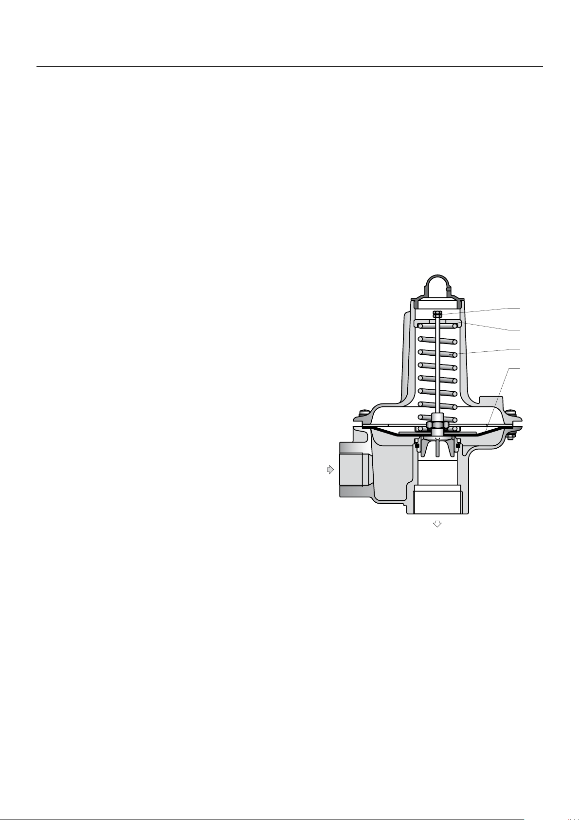
Figure 3. Closed V/50 Relief Valve
Whenever gas pressure under diaphragm (D) is higher than
the force exerted by spring (M), diaphragm is raised causing
sleeve (O), which is integral with the diaphragm itself, to
move and thereby open the release orice.
In order to check the efciency of the relief valve, pull up
valve opening stem (S).
Valve setting is carried out by adjusting the compression of
spring (M) through the appropriate ring (G).
Valve set point should generally be at an intermediate value
between active regulator or monitor and slam-shut valve
(if tted) set points.
In all other cases, it is recommended that relief valve be set
at a value at least 15% higher than the working pressure of
the equipment.
3

V Series
M
O
P
G
Ø B
63,5
Type V/20-2
A
C
Figure 4. Closed V/20-2 Relief Valve
Whenever gas pressure under pad (O) is higher than
the force exerted by spring (M) in the opposite direction,
pad older device (P) is raised, thereby causing the release
orice to open.
Setting is carried out by adjusting the compression of spring
(M) through the appropriate ring (G).
It is recommended that relief valve be set at a value at least
15% higher than the operating pressure of the station.
DIMENSIONS AND WEIGHTS
V/50 and V/60 Series
TYPE V/50 SERIES V/60 SERIES
Table 2. V Series Dimensions (mm)
D
Figure 5. V/50 and V/60 Series Dimensions
Type V/20-2
133
A 236 258
B 164 198
C 43 70
D 95 110
Weight (Kg) 1,3 1,9
4
Figure 6. Type V/20-2 Dimensions (mm)
Valve Weight 1.6 Kg
 Loading...