

Page 1
FCC ID NOTICE
This device complies with Part 15 of the FCC rules. Operation is s
ubject to the following conditions:
1. This device may not cause harmful interference, and
2. This device must accept any interference received, including inte
rference that may cause undesired operation.
CAUTION: Changes or modifications not expressly approved by the part responsible for compliance void the user’s authority to operate
www.security.soundstream.com
this device.
RS.1
REMOTE VEHICLE STARTER
INSTALLATION GUIDE
REV.5
Page 2

SYSTEM PROGRAMMING - Menu 1
PAGE 2
INSTALL MANUAL
TABLE OF CONTENTS
WIRING DIAGRAM.......................................................................Page 3-4
Connector Pin Configuration
Antenna Connection
Door Lock Connector
Bypass Connector
Data Port Connector
Tach Learning..................................................................................Page 5
Auto Tach/ Tachless Learning
Hybrid Mode
Low Idle Learn
Wire Description.............................................................................Page 6-7
6-Pin Ignition Connector
2-Pin Park Light & Ground Connector
3-Pin Lock & Unlock Connector
3-Pin Bypass Module Connector
9-Pin Connector
Transmitter Programming..............................................................Page 8
Programming Remote Transmitters
Program Mode.................................................................................Page 9
Enter Program Mode
Selecting Program Menu
Selecting The Programmable Setting
Changing The Programmable Setting
System Reset
Program Menus.........................................................................Page 10-11
Programming Menus 1-4
Diagnostics....................................................................................Page 12
2 Button Remote Notes.................................................................Page 13
****How to use the 2 button remote for programming and other functions.
Door Lock Diagrams................................................................Page 14-15
Contact Info...................................................................................Page 16
RS.1
Page 3
(+/-) GLOW PLUG/ WAIT TO START TIMER/ TRIGGER TO START
SYSTEM PROGRAMMING - Menu 1
PAGE 3
RS.1
INSTALL MANUAL
WIRE DIAGRAM
1
5
3
2
4
6
1
2
3
4
5
6
7
8
9
1
2
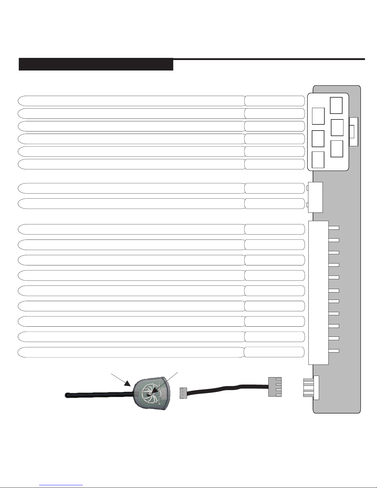
SYSTEM GROUND INPUT/ CHASSIS GROUND
SELECTABLE PARK LIGHT OUTPUT (DEFAULT POSITIVE)
STATUS LED
PROGRAM / VALET BUTTON
BLACK
WHITE
OUTPUT TO ACTIVATE IGNITION CIRCUITTHE PRIMARY
PINK
SELECTABLE OUTPUT* (DEFAULT 2ND IGNITION)
PINK/WHITE
12VOLT/ 30 AMP MAIN POWER INPUT RED
OUTPUT TO ACTIVATE THE STARTER CIRCUIT
PURPLE
12VOLT/ 30 AMP MAIN POWER INPUT RED
OUTPUT TO ACTIVATE ACCESSORY CIRCUITTHE
ORANGE
(-) AUX 1 OUTPUT - (HOLD UNLOCK & START
ORANGE/BLACK
N/A
RED/WHITE
(-) REARM OUTPUT - (PULSE WITH LOCK AND AFTER START)
GREEN/WHITE
(-) DISARM OUTPUT (PULSE WITH UNLOCK & BEFORE START)
GREEN/BLACK
(AC) TACH DETECTION INPUT (CONNECT TO COIL, INJECTOR...)
PURPLE/WHITE
(-) HOOD PIN SWITCH INPUT (GROUND WHEN HOOD IS OPENED)
GRAY
(+) BRAKE SWITCH INPUT (12VOLT WHEN BRAKE IS PRESSED)
BROWN
GRAY/BLACK
(-) HORN OUTPUT - PROGRAMMABLE
BROWN/WHITE
DO NOT INSTALL THIS SYSTEM INTO A MANUAL TRANSMISSION VEHICLE!!
Page 4
SYSTEM PROGRAMMING - Menu 1
PAGE 4
INSTALL MANUAL
WIRE DIAGRAM
1
2
3
1
2
3
1
2
3
4
Position 1 or Position 2
GREEN
BLUE
N/A*
N/A
BLACK
ORANGE
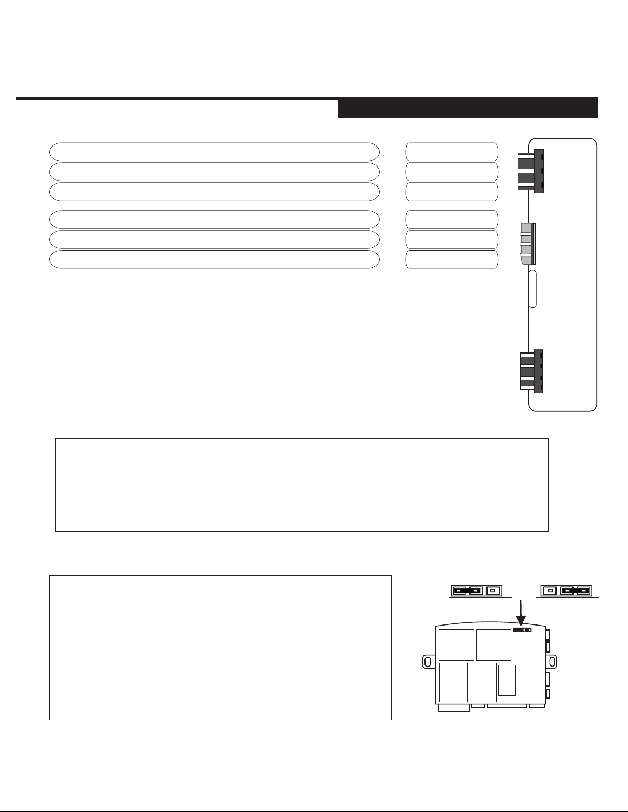
SELECTABLE PARK LIGHT OUTPUT
OUTPUT TO ACTIVATE DOOR LOCK CIRCUIT (-)
OUTPUT TO ACTIVATE DOOR UNLOCK CIRCUIT (-)
OUTPUT FOR VOLTAGE INVERTER*
N/A
GROUND FOR BYPASS MODULE
GROUND WHEN RUNNING (BYPASS TURN ON)
* THE CENTER PIN OF THE KEYLESS CONNECTOR IS LOW CURRENT AND
IS DESIGNED TO SUPPLY POWER TO DOOR LOCK MODULES (DO NOT
CONNECT TO RELAYS) OVERLOADING THIS OUTPUT WILL DAMAGE THE
MODULE!
** FOR USE WITH COMPATIBLE BYPASS MODULES ONLY.
BY DEFAULT THE SYSTEM COMES WITH THE PARK
LIGHT JUMPER SET FOR POSITIVE PARK LIGHT
OUTPUT. TO CHANGE THE SYSTEM TO A NEGATIVE
PARK LIGHT OUTPUT, PLACE THE JUMPER IN THE
NEGATIVE PARK LIGHT POSITION SHOWN IN THE
DIAGRAM. (Position 2)
*THE PARK LIGHT RELAY WILL NOT “CLICK” WHEN
SET FOR NEGATIVE PARK LIGHTS.
POSITIVE
PARK LIGHT
NEGATIVE
PARK LIGHT
RS.1
BYPASS MODULE DATA COMMUNICATION PORT
The default setting is set for FORTIN™ Bypass Modules.
Page 5
AUTO TACH/ TACHLESS LEARNING
HYBRID MODE‘S
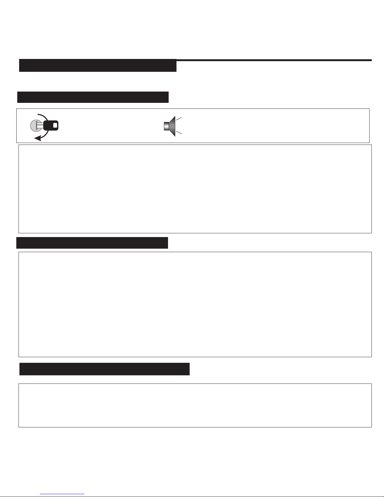
Start the vehicle with
the ignition key.
2 CHIRPS/ 2 FLASHES = TACH MODE
NOTES:
When tach learning the system first sends out a request for tach from the data port. If it gets a
valid rpm response over 750 rpm then it goes into data tach mode (3 flashes). If there is no
response, the unit will look for the tach/tachless.
Once the starter goes on then off, the unit will learn tach, if there is no tach detected within a few
seconds after starting, the system will learn in Tachless mode after 20 seconds.
If there is no starter detected, the system learns tach after 30 seconds. If no tach is detected the
system will learn tachless after an additional 10 seconds.
Hybrid mode 1 - This option requires a tach connection. Once the vehicle starts the system will not monitor
the tach input and stay running for 15 minutes.
Hybrid Mode 2- (No Tach wire connection)This setting will power up the ignition wires, pulse the start output
for 2 seconds then stay on/ run for 15 minutes. See Program Menu 4, Hybrid Mode 1& 2. Hybrid mode 2 was
designed for hybrid vehicles that may not actually start until the battery voltage
drops.
**Hybrid Mode 2 is also ideal for vehicles with no starter wire or “Automatic Starting”. This is when the
vehicle’s starter motor will continue to crank and start the vehicle even if the key is only turned to the start
position momentarily.
“Push to Start” systems and
Hold the brake then start the vehicle with the key. Place the transmission into reverse to lower the
RPM. Press and release the button on the antenna twice. The system will chirp the Horn and
flash the park lights two times to confirm Tach Mode or chirp 4 times/ 4 flashes to indicate
Tachless Mode re-learn.
LOW IDLE LEARNING
4 CHIRPS/ 4 FLASHES = TACHLESS MODE
3 CHIRPS/ 3 FLASHES = DATA TACH MODE
SYSTEM PROGRAMMING - Menu 1
PAGE 5
INSTALL MANUAL
TACH LEARN
RS.1
Page 6
PIN 1
PIN 1
PURPLE
BLACK
PIN 2
PIN 2
ORANGE
WHITE
PIN 3
RED
PIN 4
RED
PIN 6
PINK
PIN 5
PINK/
WHITE
STARTER
OUTPUT
SYSTEM
GROUND
This wire will test 0V with the key off, in the Accessory position and when the
Ignition is in the on. This wire is 12volts in the start/ crank position only.
Connect to chassis ground.
HEATER
OUTPUT
PARK LIGHT
OUTPUT
(SELECTABLE)
This wire will test 0V when key is off, 12volts in the ACC and IGN positions
and off during the start/ crank position
Connect to the vehicles positive park light wire or change the jumper and
connect to the vehicle negative park light wire. The default position of the
jumper is Positive Park Light Output.
12v INPUT 30A
Connect to constant 12volts. This input supplies the 12volt power for the
IGN 1, IGN 2 and Park Light output.
12v INPUT 30A
Connect to constant 12volts. This input supplies the 12volt power for the
Accessory and Starter output.
IGNITION
OUTPUT
This wire will test 0V in the off and Accessory positions then switch to12volts
in the Ignition and Start and run position.
SELECTABLE
OUTPUT
2nd Ignition, Accessory or Start output. Programmable.
Note: This output does not switch to default when the system is reset.
PIN 1
GREEN
PIN 2
N / A
PIN 3
BLUE
(-) LOCK
OUTPUT
Connect to lock wire from the switch on vehicles with a negative type switch.
**LOW CURRENT ONLY**
12V + DOOR
LOCK INVERTER
This output will supply 12volts for a plug-in type door lock module. Do not
use this input to power-up relays **LOW CURRENT ONLY**
(-) UNLOCK
OUTPUT
Connect to unlock wire from the switch on vehicles with a negative type
switch. **LOW CURRENT ONLY**
6-PIN CONNECTOR 9-PIN CONNECTOR
2-PIN CONNECTOR
3 PIN DOOR LOCK CONNECTOR
SYSTEM PROGRAMMING - Menu 1
PAGE 6
INSTALL MANUAL
WIRE DESCRIPTION
PIN 1
ORANGE
PIN 2
BLACK
PIN 3
N/A
GROUND WHEN
RUNNING
This wire is used for bypass module activation or adding additional relays to
be triggered only when the remote starter activates.
GROUND
This wire can be used to supply ground to your bypass module.
3 PIN BYPASS MODULE CONNECTOR
RS.1
Page 7
PIN 1
GREEN/
WHITE
PIN 2
GREEN/
BLACK
PIN 3
ORANGE/
BLACK
PIN 4
PIN 7
RED/
WHITE
GRAY
PIN 5
PIN 8
BROWN/
WHITE
VIOLET/
WHITE
PIN 6
PIN 9
BROWN
GRAY
RE-ARM (-)
PROGRAMMABLE
Supplies one .75 second pulse when locked and one .75 second pulse
after remote start shutdown. Factory alarm re-arm/ RAP shutdown.
DISARM (-)
Supplies one .75 second pulse when the unlock button is pressed and
one .75 second pulse before remote start activation. For factory alarm disarm/ or as computer “wake up”.
AUX #1
OUTPUT (-)
PROGRAMMABLE
Default- AUX channel output when the Unlock and START buttons are
held (no car finder) Programmable for a (-) Ignition or (-) Dome Light
output with the activating car finder mode. Unlock and START buttons
N/A
HOOD PIN
INPUT (-)
N/A
Connect this wire to the supplied hood pin switch. If ground is detected on
this input the remote starter will not activate. Programmable for N/C hood
pin type (Factory hood pin)
HORN
OUTPUT (-)
PROGRAMMABLE
TACH WIRE
INPUT (A/C)
Connect this wire to the factory horn wire of the vehicle. This connection
will provide audible confirmation when programming and when a function
is performed.
This wire is used to to detect when the vehicle has started. The Tach
source is typically taken from a fuel injector, coil, coil pack or crank
position sensor. The Tach wire is generally found as the opposite from the
common wire at the coil or fuel injector.
BRAKE
SWITCH
INPUT (+)
GLOW PLUG
INPUT (+)
This wire must be connected to the wire at the brake switch that changes
to 12volts when the brake is pressed.
Default Gas Mode/ Positive Glow Plug. Programmable.
SYSTEM PROGRAMMING - Menu 1
PAGE 7
INSTALL MANUAL
WIRE DESCRIPTION
RS.1
Page 8
SYSTEM PROGRAMMING - Menu 1
PAGE 8
INSTALL MANUAL
TRANSMITTER PROGRAMMING
RS.1
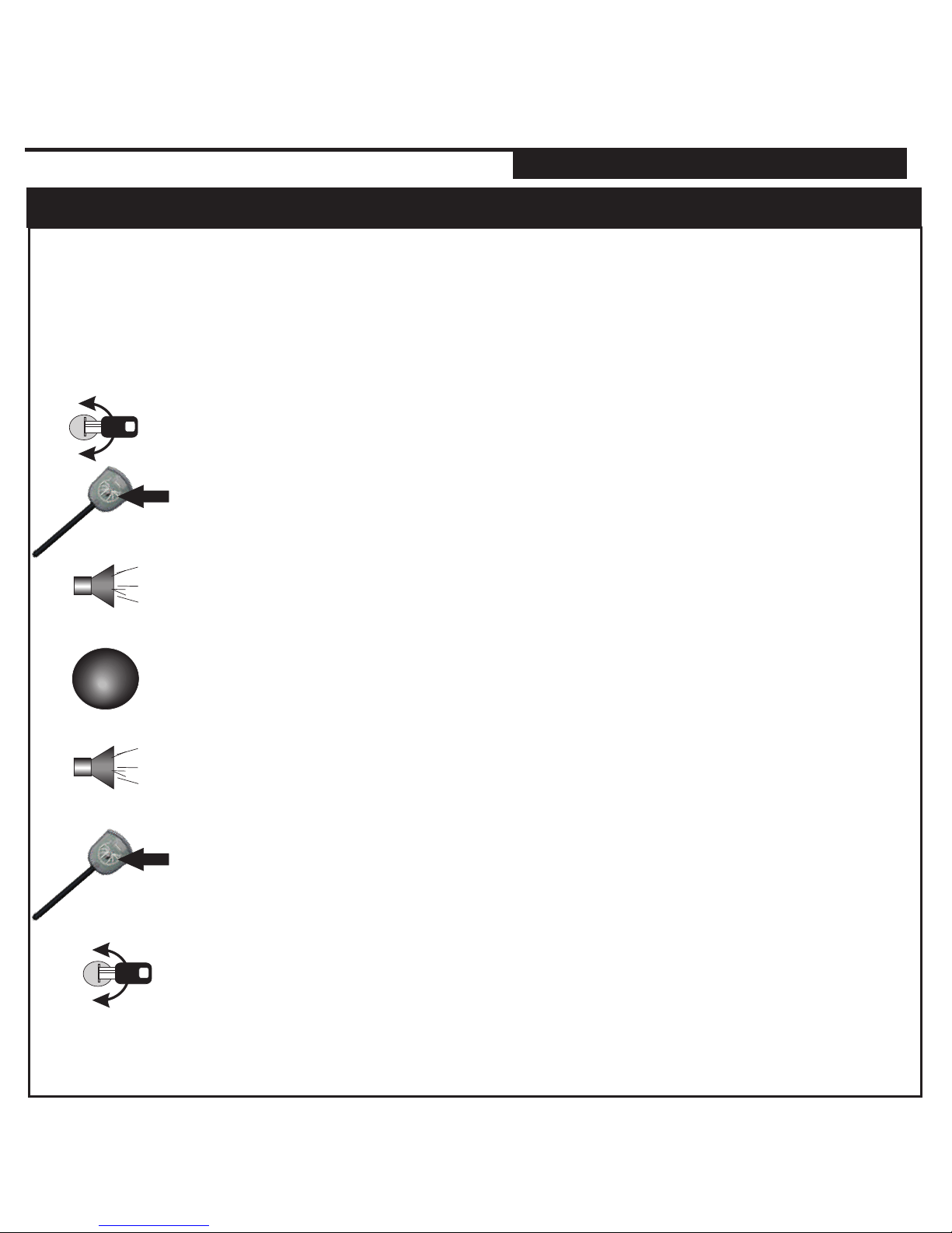
PROGRAMMING ADDITIONAL TRANSMITTERS
Turn ignition key OFF to exit remote program mode when all
required remote’s have been programmed.
1 Honk confirms program mode was entered followed by
5 Honks confirming transmitter program mode.
Press and HOLD the valet switch (The Park Light will turn on)
If connected the Horn will Honk once
Continue Holding until the lights turn off and the honk honks 5 times
Cycle the Ignition Key - ON/OFF ON/OFF ON
(Leaving the key ON)
ENTERING REMOTE PROGRAM MODE
The system can lean up to 4 different remote’s. Each remote to be used MUST be
programmed together during the same sequence. For security, when a new remote
is programmed all previous remote’s are deleted.
Press and release the Lock/ Unlock button on each of the
transmitter’s to be programmed. The park lights will flash once for
each added transmitter code.
The horn will also confirm each new transmitter by honking once.
Release the valet switch once all transmitter’s are entered.
*Maximum 4 remote’s
Page 9
SYSTEM PROGRAMMING - Menu 1
PAGE 9
INSTALL MANUAL
PROGRAMMING
RS.1
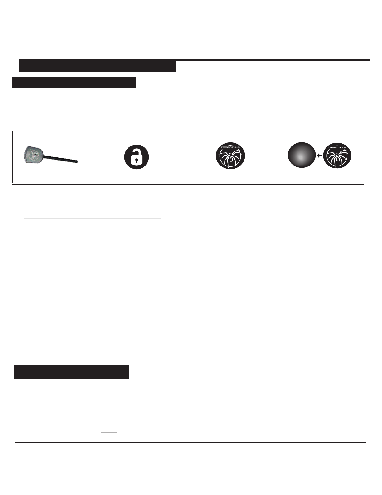
Press Antenna
Press Unlock
MENU 1 MENU 2 MENU 3 MENU 4
1 - Cycle the Ignition Key On/Off On/Off On (Leaving the key ON)
2 - Press and release the Program Switch 1 time. The park lights will turn on and the horn
will honk to confirm entering program mode.
3 - Select the Program Menu by pressing...
ENTERING PROGRAM MODE
1 - Cycle the Ignition Key On/Off On/Off On (Leaving the key ON)
2 - Press and RELEASE the Program Switch 1 time and the park light will turn on.
(Horn will honk to confirm program mode has been entered)
3 - Press and HOLD the Program Switch for 5 seconds or until the Park Lights flash 3 times.
4 - Turn the ignition key OFF to exit.
(Confirmed by 3 Park Lights flashes/ Horn Honks)
SYSTEM RESET
The system will confirm the program menu by flashing the park lights and with horn honks.
4 - Press and Release the Program Switch to advance through the settings.
(Confirmed by Park Lights/ Horn Honks & LED flashes)
5 - Press and Hold the Program Switch to change the setting.
(Confirmed by Park Lights/ Horn Honks & LED flashes)
6 - To exit Program Mode, turn the key off.
(Confirmed by Long Horn Honk)
Example- Programming Menu 1, Setting 3 to Double Lock Pulse.
1 - Cycle the Ignition Key On/Off On/Off On
2 - Press and release the Program Switch 1 time. (1 Honk/ Park Lights ON)
3- Press and release the Antenna button to advance in Menu 1. (1 Honk/ 1 flash)
4- Press and release the program button until the LEDs on the antenna flash 3 times.
**The park lights will flash and the Horn will Honk 3 times to confirm the current setting)
5- Press and hold the program button. The Park Light will flash once (option 1), pause then flash
twice to confirm option 2 has been selected. The Horn will also Honk 1 time (option 1) then 2
times to confirm the option 2.
6- Release the program switch and turn off key to exit.
Press Start Unlock & Start
Page 10
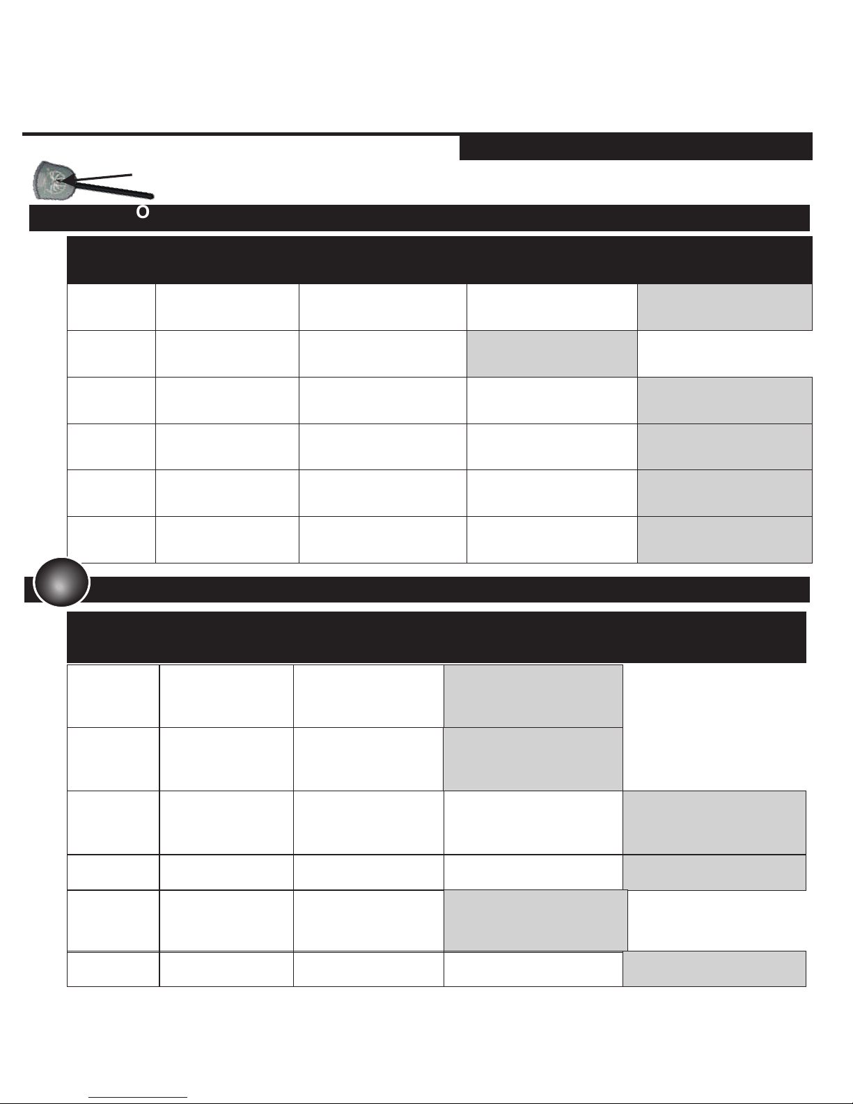
SETTING #
LED
FLASHES
SETTING
DESCRIPTION
OPTION 1
1 CHIRP
OPTION 2
2 CHIRPS
OPTION 3
3 CHIRPS
1
2
3
VALET SETTINGS
SECURE VALET
15 SECONDS
STANDARD VALET
5 SECONDS
PARK LIGHT
OUTPUT
30 SECONDS ON
DISARM
NORMAL OPERATION
HORN TIMING 5MS PULSED OUTPUT 50MS PULSED OUTPUT 10MS PULSED OUTPUT
PROGRAM MODE 1
PROGRAM MODE 2
IGNITION AUTO-LOCKS
DISABLED
SETTING #
LED
FLASHES
SETTING
DESCRIPTION
OPTION 1
1 CHIRP
OPTION 2
2 CHIRPS
OPTION 3
3 CHIRPS
1
2
3
4
5
6-9 NA
IGNITION
AUTO-LOCK
IGNITION AUTO-LOCK /
UNLOCK
IGNITION AUTO-LOCK
ONLY
HORN SETTINGS
HORN
CHIRPS DISABLED
HORN
CHIRPS ENABLED
DOOR LOCK PULSE
OPTIONS
DOUBLE UNLOCK &
SINGLE LOCK
DOUBLE LOCK & SINGLE
UNLOCK
SINGLE LOCK & SINGLE
UNLOCK
DOOR LOCK /
UNLOCK PULSES
0.25 SEC PULSES 3 SEC PULSES 0.75 SEC PULSES
AUX OUTPUT 1
(-) IGNITION OUTPUT
UNLOCK & TRUNK
ACTIVATES CAR FINDER
N/A
(-) DOME LIGHT OUTPUT
UNLOCK & TRUNK
ACTIVATES CAR FINDER
N/A
AUX CHANNEL
HOLD UNLOCK & TRUNK
N/A
N/A
SYSTEM PROGRAMMING - Menu 1
PAGE 10
INSTALL MANUAL
PROGRAM MENU 1 & 2
4
N/A N/A N/A N/A
5 HOOD PIN TYPE N/C FACTORY TYPE AFTER MARKET TYPE
6
N/A N/A N/A N/A
RS.1
Press and release the Valet Button to advance through Menu 1 settings.
Page 11
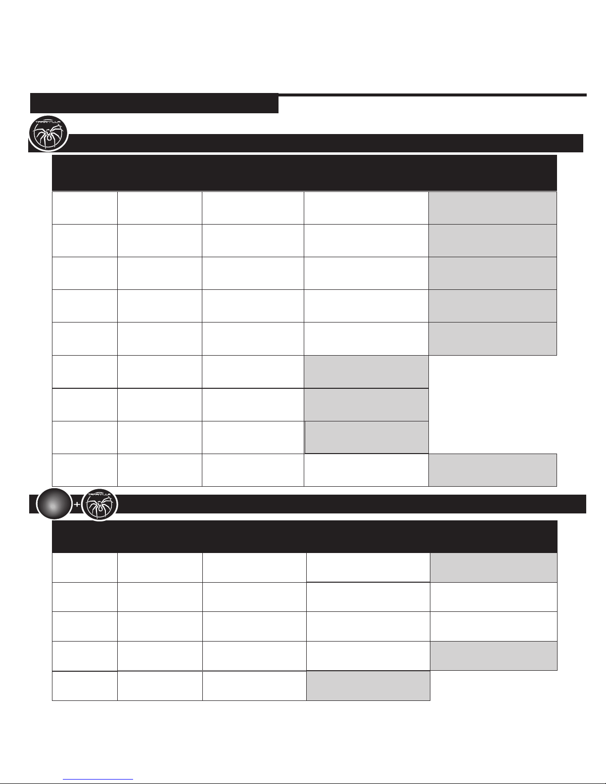
5
BYPASS MODULE IDATA™ LINK BYPASS
FORTIN™ BYPASS
8
SPECIAL
DISARM
PULSES ACC & GWR
WHEN UNLOCKED
NORMAL DISARM
9
UNLOCK BUTTON
1 / 2 BUTTON
REMOTE ONLY
UNLOCK AND
START FOR TIMER
MODE & MENU 4
UNLOCK / LOCK TOGGLE
UNLOCK AND START FOR
TIMER MODE & MENU 4
UNLOCK OUTPUT
2ND
IGNITION
SETTING #
LED
FLASHES
SETTING
DESCRIPTION
OPTION 1
1 CHIRP
OPTION 2
2 CHIRPS
OPTION 3
3 CHIRPS
1
2
3
4
5
6
SELECTABLE
RELAY
2ND
STARTER
2ND ACCESSORY
SPECIAL DOOR
LOCK OPTIONS
UNLOCK BEFORE /
LOCK AFTER START
LOCK AFTER STARTER
SHUT OFF
NO ADDITIONAL PULSES
GLOW PLUG/
START TRIGGER
(-) GLOW PLUG OR
20 SECONDS DELAY
(+) START TRIGGER (2
PULSES)10 SECOND
DELAY TO START
GAS/ POSITIVE GLOW
PLUG
RE-ARM
OPTIONS
PULSE WITH LOCK
PULSE AFTER START
(DEFROST / SEAT)
PULSE WITH LOCK &
AFTER SHUTDOWN
RUNTIME 4 MINUTE RUNTIME
PRESS BUTTON ONCE TO
START
45 MINUTE RUNTIME 15 MINUTE RUNTIME
REMOTE START
ACTIVATION
PRESS BUTTON
TWICE TO START
PROGRAM MODE 3
PROGRAM MODE 4
AUTO TACH / TACHLESS
SETTING #
LED
FLASHES
SETTING
DESCRIPTION
OPTION 1
1 CHIRP
OPTION 2
2 CHIRPS
OPTION 3
3 CHIRPS
1
2
3
4
TACH OPTIONS HYBRID MODE 1
ADJUST FOR
OVER-CRANK
INCREASES TACH
SETTING BY 10%
ADJUST FOR
UNDER-CRANK
DECREASE TACH
SETTING BY 10%
TACH WAIT
SETTINGS
300ms TACH CHECK
DELAY
750ms TACH CHECK
DELAY
NO TACH CHECK DELAY
7
LEDS FLASH WHEN
LOCKED/ ARMED
LED FLASHES
LEDS DO NOT FLASH
WHEN LOCKED/
ARMED
HYBRID MODE TWO
SYSTEM PROGRAMMING - Menu 1
PAGE 11
INSTALL MANUAL
PROGRAM MENU 3 & 4
RS.1
Page 12
SYSTEM PROGRAMMING - Menu 1
PAGE 12
INSTALL MANUAL
DIAGNOSTICS
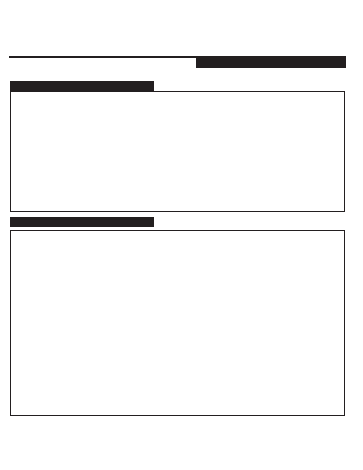
DIAGNOSTICS CHART
TO ENTER DIAGNOSTIC MEMORY
If the remote starter does not activate when the start button is pressed the park lights will flash a diagnostic
to indicate what shutdown input has been triggered. For example: If the start button is pressed the park
lights flash 3 times slowly. Looking at the chart below this would indicate that the system is in Service Mode,
simply follow the instructions listed in the owners manual on exiting Service Mode and the remote starter
will begin to function as normal.
PARK LIGHTS STATUS LED DIAGNOSTIC CODE
3 Slow Flashes LEDs “ON” Solid System Is In Service Mode
4 Slow Flashes Series of 4 Flashes Not in Reservation Mode
5 Flashes Series of 5 Flashes Hood Open
5 Slow Flashes Series of 5 Flashes Ignition On During Start Attempt
6 Flashes Series of 6 Flashes Brake Pedal Shutdown
7 Flashes Series of 7 Flashes Tach Lock-Out
8 Flashes Series of 8 Flashes 3 Start Attempts Without Starting
Step 1- Turn the ignition ON then OFF. Press and release the Program Button.
Step 2- The system will respond with three park light flashes and the HORN (optional) will honk the same
number of times as the events in memory.
****Maximum four events, four honks****
NOTE: If the HORN does not honk, there are no events in memory.
Step 3- Press the Program Button once to view the last shut down code. The HORN (optional)will honk
once to confirm code one.
****If the HORN does not honk, there are no codes in memory.****
Step 4- The LEDs on the antenna will flash a code corresponding to a shut down trigger. Press the
Program Button again for the second code.
***The HORN will honk twice to confirm code two three time for code three...***
Step 5- To Clear Diagnostic Memory. While in Diagnostic Mode press and hold the
Program Button for five seconds. The park lights will flash and the HORN (optional)
will honk once.
****Once diagnostic memory has 4 shutdown events in memory, the system will not record any further
shutdown events until the system memory has been cleared.****
LED Flashes Diagnostic
5 Flashes The system was shutdown by the brake switch input
6 Flashes The system was shutdown by the hood pin input
7 Flashes The system did not detect the Tach signal.
8 Flashes The system made 3 start attempts without starting
RS.1
Page 13
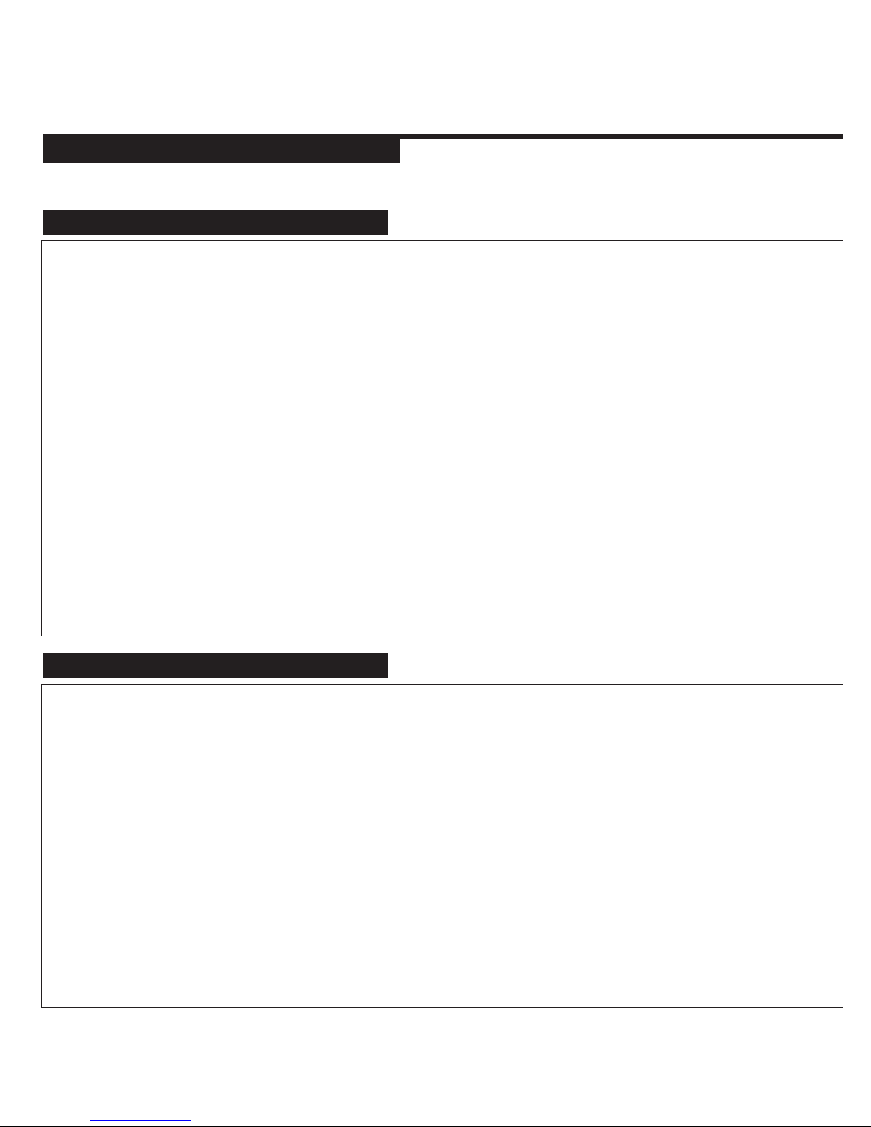
2 BUTTON REMOTE
INSTALLER NOTES
SYSTEM PROGRAMMING - Menu 1
PAGE 13
INSTALL MANUAL
INSTALLATION NOTES
WHEN PROGRAMMED FOR 2 BUTTON OR LOCK/UNLOCK TOGGLE PRESSING UNLOCK
AND START AT THE SAME TIME WILL SELECT MENU 4 WHILE IN PROGRAM MODE.
THE SYSTEM MUST BE PROGRAMMED FOR 2 BUTTON REMOTE LOCK/UNLOCK
TOGGLE TO OPERATE THE LOCK FEATURE ON THE VEHICLE. PRESSING THE UNLOCK
BUTTON WILL UNLOCK THE DOORS THEN THE NEXT TIME YOU PRESS THE BUTTON
THE DOORS WILL LOCK.
WHEN PROGRAMMED FOR 2 BUTTON OR LOCK/UNLOCK TOGGLE PRESSING UNLOCK
AND START AT THE SAME TIME WILL SELECT 4 HOUR TIMER IN COLD START MODE*.
TO ACCESS TIMER MODE AND FOUR HOUR TIMER. HOLD THE UNLOCK AND START
BUTTONS TO ENTER COLD START MODE. PRESS UNLOCK TO SET 2 HOUR, START
WILL SET THREE HOUR AND UNLOCK AND START TOGETHER WILL SET THE FOUR
TIMER. PRESS AND RELEASE UNLOCK AND START TO CANCEL TIMER MODE ONCE
SET.
*ONE HOUR TIMER MODE IS NOT AVAILABLE WITH 2 BUTTON REMOTE’S.
RS.1
Page 14
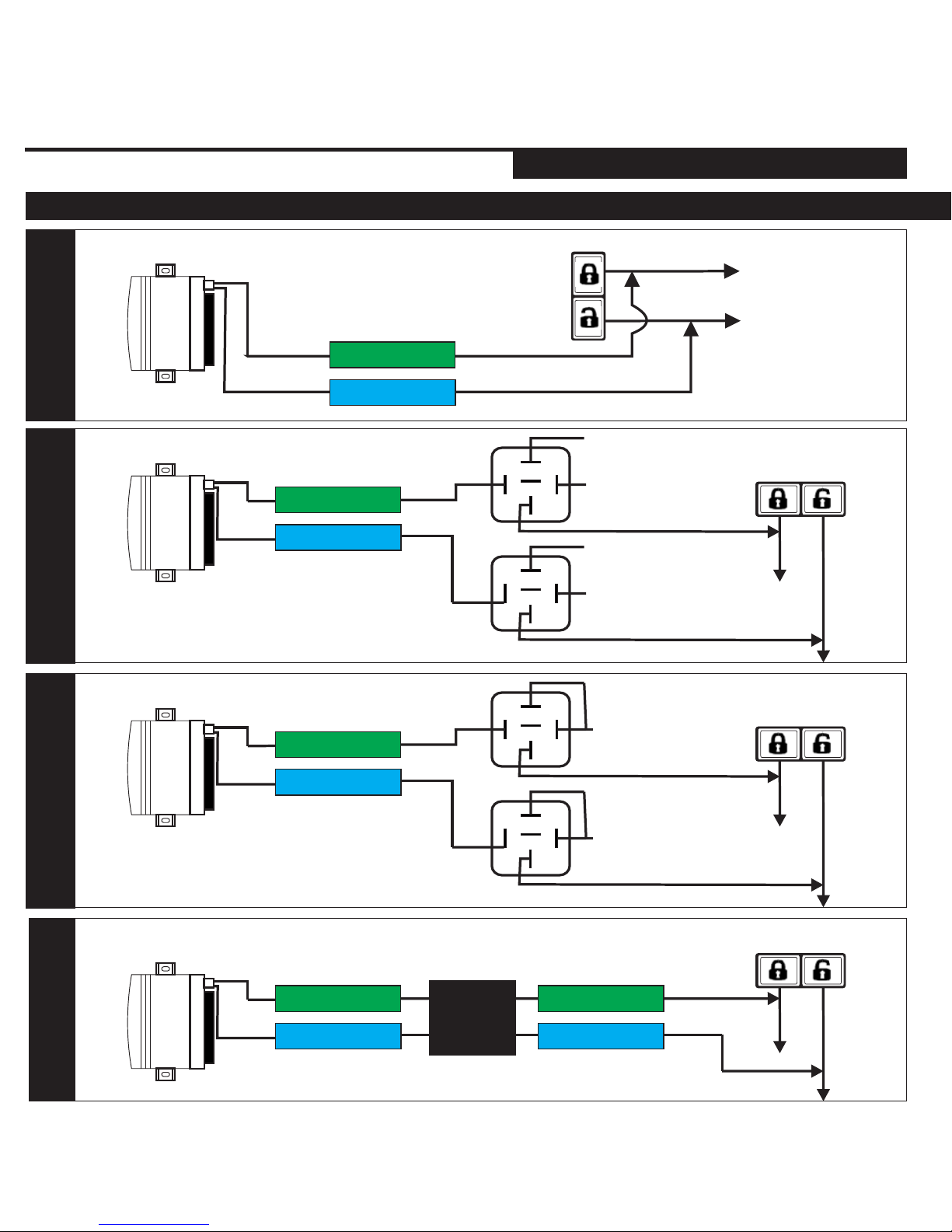
DOOR LOCK DIAGRAMS
Green
Vehicle's Lock/Unlock Switch
To Control
Relay or
Actuators
NEGATIVE DOOR LOCK
(LOW CURRENT)
Alarm and / or Starter
Module
Door lock Output
SYSTEM PROGRAMMING - Menu 1
PAGE 14
INSTALL MANUAL
RELAY DIAGRAMS
Vehicle's Lock/
Unlock Switch
USE SPDT 12v Relay
Blue
NEGATIVE DOOR LOCK
(LOW CURRENT)
Ground
Ground
12volts
12volts
87
86
85
87a
30
87
86
85
87a
30
Alarm and / or Starter
Module
Door lock Output
Blue
Green
Vehicle's Lock/
Unlock Switch
USE SPDT 12v Relay
POSITIVE DOOR LOCK
(LOW CURRENT)
12volts
12volts
87
86
85
87a
30
87
86
85
87a
30
Alarm and / or Starter
Module
Door lock Output
Blue
Green
POSITIVE TYPE USING
INVERTER
Alarm and / or Starter
Module
Door lock Output
Blue
Green
VOLTAGE
INVERTER
Vehicle's Lock/ Unlock Switch
Blue
Green
RS.1
Page 15
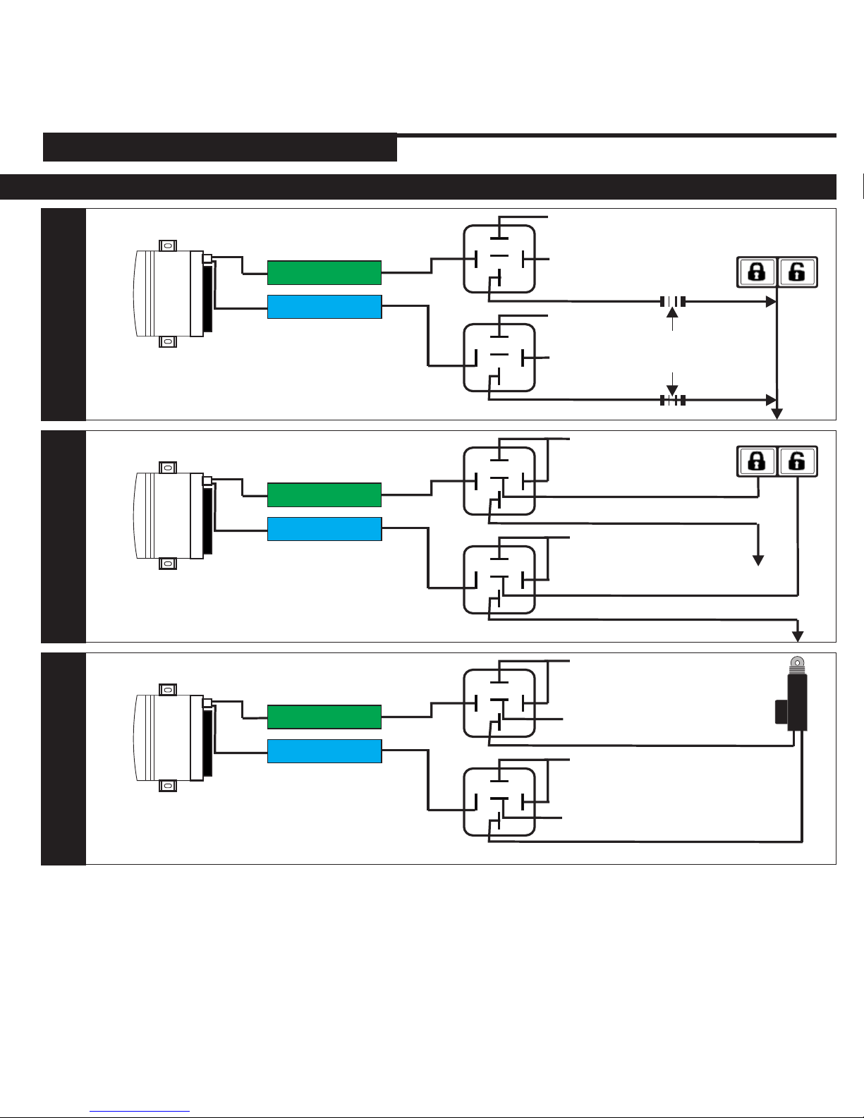
SYSTEM PROGRAMMING - Menu 1
PAGE 15
INSTALL MANUAL
RELAY DIAGRAMS
Vehicle's Lock/
Unlock Switch
USE SPDT 12v Relay
NEGATIVE ONE WIRE
DOOR LOCKS
Ground
Ground
12volts
12volts
87
86
85
87a
30
87
86
85
87a
30
Alarm and / or Starter
Module
Door lock Output
Blue
Green
Unlock Resistor
Lock Resistor
Lock/ Unlock Switch
USE SPDT 12v Relay
REVERSE POLARITY DOOR
LOCK SYSTEM
12volts
12volts
Alarm and / or Starter
Module
Door lock Output
Blue
Green
87
86
85
87a
30
87
86
85
87a
30
x
x
x
x
USE SPDT 12v Relay
AFTER-MARKET DOOR
LOCK ACTUATORS
12volts
12volts
Alarm and / or Starter
Module
Door lock Output
Blue
Green
87
86
85
87a
30
87
86
85
87a
30
Ground
Ground
DOOR LOCK DIAGRAMS
RS.1
Page 16
website: www.security.soundstream.com
tech support: [email protected]
 Loading...