

Page 1
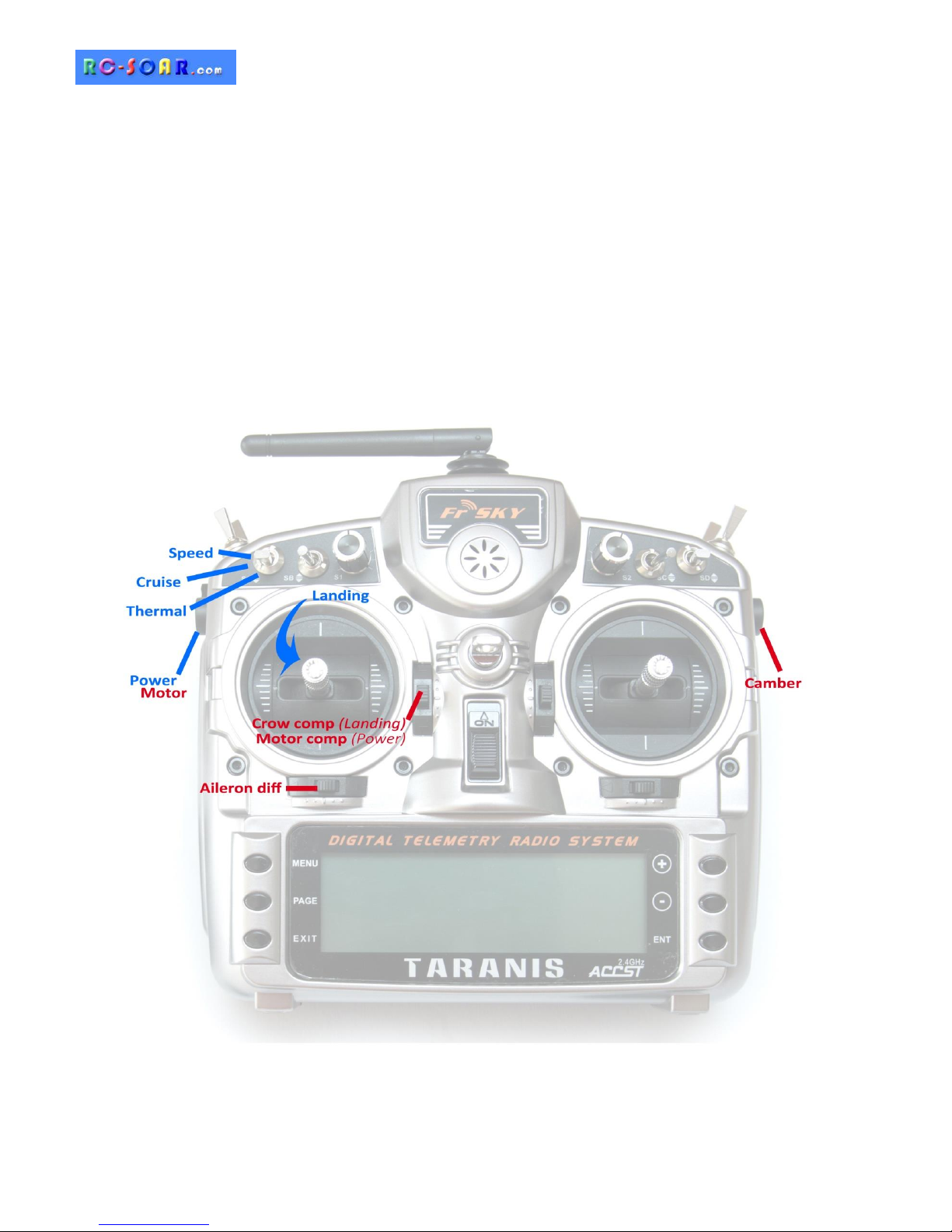
Copyright © Michael Shellim
E-Soar Plus for Taranis & Horus
Version 3.0
Setup Guide
Mike Shellim
28 Jan 2018
Page 2

Page 2 rev 3.0.03
Table of Contents
1 Introduction ............................................................................................................................ 3
1.1 Package contents ............................................................................................................................... 3
1.2 Requirements ..................................................................................................................................... 3
1.3 Flight modes ....................................................................................................................................... 3
1.4 Stick mode and assignments .............................................................................................................. 3
1.5 Mixers ................................................................................................................................................. 4
1.6 Channel assignments ......................................................................................................................... 4
2 Operational Overview .............................................................................................................. 4
3 Motor operation ...................................................................................................................... 5
3.1 Arming the motor .............................................................................................................................. 5
3.2 Running the motor ............................................................................................................................. 5
3.3 Disarming the motor .......................................................................................................................... 5
4 Flight timer .............................................................................................................................. 5
5 CAL mode ................................................................................................................................ 5
6 Setting up your transmitter ...................................................................................................... 6
6.1 Preparing the transmitter .................................................................................................................. 6
6.1.1 Transfer template to transmitter............................................................................................. 6
6.1.2 Hardware calibration ............................................................................................................... 6
6.1.3 Corrections for different transmitters ..................................................................................... 7
6.1.4 Familiarisation.......................................................................................................................... 7
6.2 Calibrating the servos ........................................................................................................................ 7
6.2.1 Set servo rotation .................................................................................................................... 7
6.2.2 Adjust end-points and centres ................................................................................................. 8
7 Configuring inputs and mixers ................................................................................................ 10
8 Motor safety check ................................................................................................................ 12
9 Summary of in-flight adjusters ............................................................................................... 13
10 Pre-flight ............................................................................................................................... 13
11 Customisations ...................................................................................................................... 13
11.1 Changing the assignments of Crow, Motor and Camber ................................................................. 13
11.2 Changing the flight mode switch ..................................................................................................... 13
11.3 Reversing the crow stick .................................................................................................................. 14
11.4 Reversing motor lever ...................................................................................................................... 14
11.5 Reversing camber lever .................................................................................................................... 14
11.6 Dual rates ......................................................................................................................................... 14
11.7 Adjusting crow stick deadband ........................................................................................................ 15
11.8 Selecting an alternative arming method .......................................................................................... 15
11.8.1 Method 1(default): stick in corner, pull SH............................................................................ 15
11.8.2 Method 2: Pull SH .................................................................................................................. 15
11.8.3 Method 3: Two-position switch ............................................................................................. 15
12 Making your own mods.......................................................................................................... 16
13 Disclaimer ............................................................................................................................. 16
14 Contact .................................................................................................................................. 16
Page 3
Page 3 rev 3.0.03
1 Introduction
E-Soar Plus is a full-feature template for full-house electric-powered gliders. It contains all the mixing
needed for F5J competition, yet is easy to configure and operate. Special attention has been paid to motor
safety. Key mixers may be adjusted in flight. An integrated flight timer is included.
Before starting please:
- read through these instructions
- visit the support page
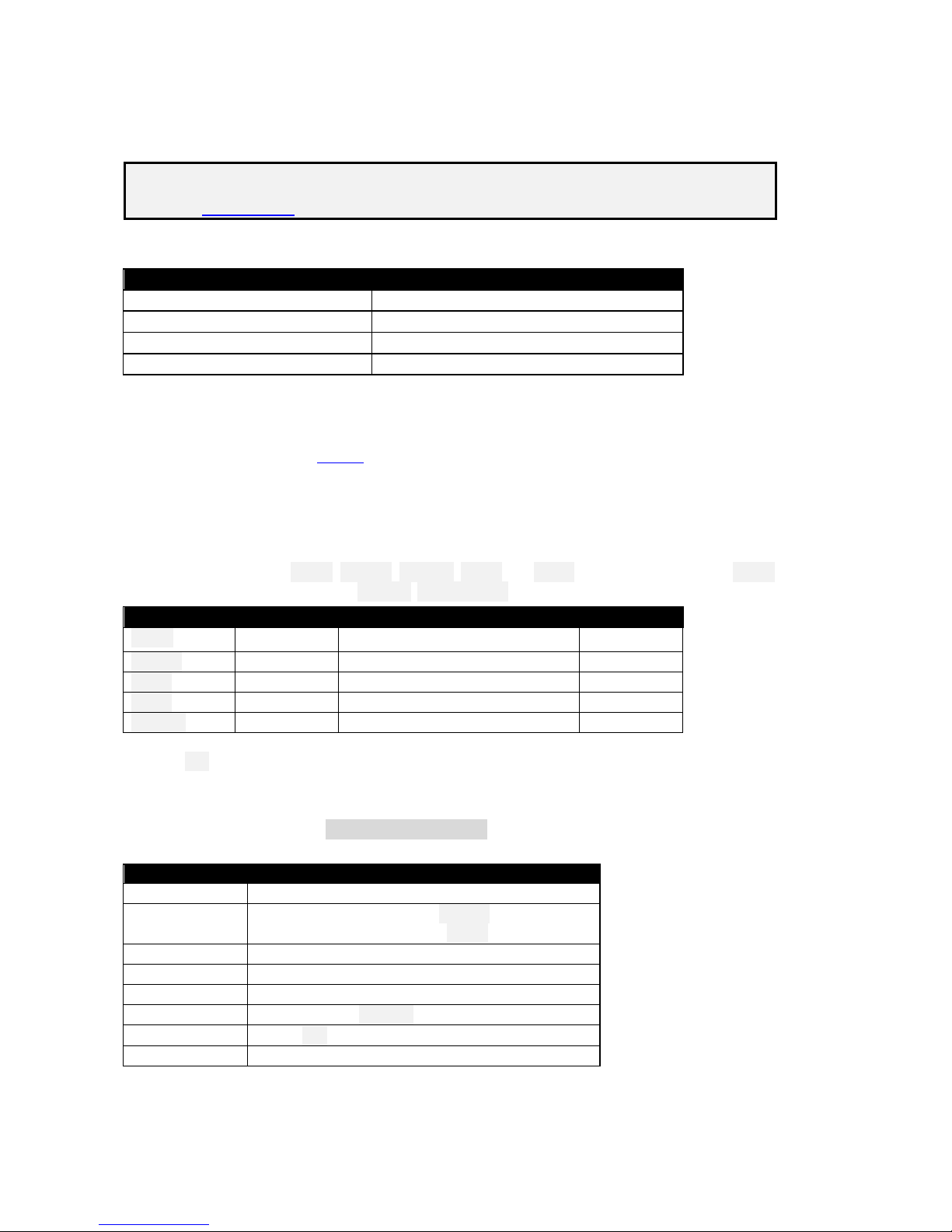
1.1 Package contents
Filename
Description
esoarplus_30_SetupGuide.pdf
Setup guide
esoarplus_30_SettingsRef.xls
Settings reference
esoarplus_30x.eepe
EEPROM images for V- and X/T- tail
esp***.wav
Sound files
1.2 Requirements
FrSky Taranis or Horus transmitter
OpenTx 2.2.1 or later (see change log for recommended versions)
OpenTx Companion software + USB cable.
Some familiarity with the OpenTx’s menus and data entry will be useful.
1.3 Flight modes
There are 5 flight modes: Power, Landing, Thermal, Cruise and Speed. In the event of a clash, Power has
highest priority, then Landing, then Thermal/ Cruise/Speed.
Flight Mode
OpenTx ID
Activated by
Priority
Power
FM2
LS↑ (if motor is armed)
High
Landing
FM3
Throttle stick ↓
Mid
Speed
FM5
SA ↑
Low
Cruise
FM4
SA ―
Low
Thermal
FM0
SA ↓
Low
A special CAL flight mode (FM1) is provided for calibrating the control surfaces.
1.4 Stick mode and assignments
This stick mode (1 – 4) is set in MODEL SETUP→STICK MODE.
Stick and switch assignments as follows:
Control
Function
Throttle stick
Crow
Throttle trim
Crow compensation adjust (Landing mode)
Motor compensation adjust (Power mode)
Rudder trim
Aileron diff adjust
SA
Flight mode selector
LS
Motor
RS
Camber adjust (Thermal mode)
SH
Cancel CAL mode, Motor arming options 1, 2
SF
Motor arming option 3
Page 4
Page 4 rev 3.0.03
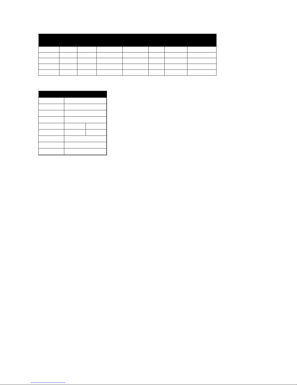
1.5 Mixers
The table below shows which mixers are active in each flight mode. Mix adjusters are in brackets.
Flight
mode
Ail→
Flap
Ail→
Rud
Motor
Comp
Crow
comp
Rev
diff
Camber
Diff
Power
Y Y Y(Thr trm)
Y(RudTrm)
Landing
Y Y
Y(Thr trm)
Y Y(RudTrm)
Cruise
Y Y Y(RudTrm)
Thermal
Y Y
Y (RS)
Y(RudTrm)
Speed
Y Y Y Y(RudTrm)
1.6 Channel assignments
Channel #
Function
1
Right aileron
2
Left aileron
3
Right flap
4
Left flap
5
Elevator
RtVee
6
Rudder
LtVee
7
Motor
8
[free]
9
[free]
2 Operational Overview
Flight trims
Aileron trim is shared across all flight modes
Elevator trim is independent for each flight mode
Rudder and throttle trims are repurposed for other functions (see below)
Camber mixes
Camber is adjustable in Thermal mode using slider RS.
Reflex (fixed) may be specified for Speed mode.
Crow compensation (crow to elevator)
Crow compensation is a variable mix which compensates for pitch changes as crow is deployed.
The amount of compensation can be adjusted during flight, via the Throttle trim.
Non-linear compensation may be applied by editing a curve
Motor compensation (motor to elevator)
Motor compensation is a variable mix which compensates for pitch changes as power is applied.
The amount of compensation can be adjusted via the Throttle trim.
Differential
Diff is applied to ailerons and flaps
Diff is adjustable via the Rudder trim.
Diff settings are stored per flight mode.
Roll rate enhancement
Aileron diff reduces to zero as crow is deployed. This helps with roll response under crow.
An adjustable ‘Reverse diff’ mix further improves roll response under braking.
Aileron to rudder (‘combi’)
Aileron to rudder mix can be applied individually for each flight mode.
Page 5

Page 5 rev 3.0.03
3 Motor operation
3.1 Arming the motor
The motor is disarmed at startup. To arm the motor:
1. Motor lever to idle (LS↓)
2. Apply full right-aileron and full up-elevator, and hold
3. Pull SH and hold for 1 second until the startup sound
4. Release SH
5. Release stick(s)
A warning beep sounds every 12 seconds to indicate that the motor is live
3.2 Running the motor
To run the motor:
1. Arm the motor
2. Push forward on LS↑
Power mode is activated automatically. Note: LS incorporates some deadband, to prevent accidental
operation of the motor.
3.3 Disarming the motor
To disarm the motor, pull SH for 1 second until the ‘motor disabled’ alert.
To minimise the risk window, arm just before launch, and disarm immediately after
landing.
The arming system does not protect against signal loss. Remember to set the failsafe, so
the motor is commanded to ‘off’ (-100) on loss of signal.
4 Flight timer
Timer1 is configured as an automatic flight timer. The timer is named ‘Flight’.
To reset: arm the motor.
To start: advance motor
To stop: disarm the motor.
5 CAL mode
CAL mode is a special flight mode for calibrating the servos. When CAL mode is active, all mixers and trims
are disabled. To enable CAL mode:
1. Apply full left aileron and full up elevator, and hold
2. Pull SH
3. Release SH
4. Release stick(s)
There are three CAL sub-modes selected via switch SA:
Mode 1 (SA↑): calibrate with reduced movement for ailerons
Mode 2 (SA―): calibrate end points and centres
Mode 3 (SA↓): calibrate flap neutral
In sub-mode 2 , the response of the throttle stick is stepped at 25% increments.
When CAL mode is enabled, a beep sounds every 3 secs and a voice alert every 9 secs.
To exit CAL mode, pull SH.
Page 6

Page 6 rev 3.0.03
6 Setting up your transmitter
Transmitter configuration is in three phases:
1. Preparation – copying files to the transmitter
2. Servo calibration – setting servo end points and centres
3. Mixer and travel adjustment
Follow the sequence exactly as shown, using tick boxes to record your progress.
Make sure that the motor is disconnected before proceeding.
6.1 Preparing the transmitter
6.1.1 Transfer template to transmitter
In this step you’ll transfer the template to your transmitter. The methods may differ slightly depending on
the model of transmitter.
Establish communication with your PC
□ Taranis: Switch on the transmitter whilst pressing horizontal trim levers towards the centre
Horus: Switch on the transmitter
□ Connect the tx to the computer via USB. The tx’s SD card should appear as an external drive.
Copy sound files
□ On your PC, extract all files from .ZIP package
□ Copy the sound files to the /SOUNDS/{language} folder on the SD card. For example, English folder
is “/SOUNDS/en”. Note: there are new sound files in version 3.
Transfer model to transmitter
□ Launch Companion
□ Open the esoarplus_30x.eepe file. Versions for X/T and V tails are displayed in a window.
□ From the File menu, choose READ MODELS AND SETTINGS FROM RADIO. The model list from the radio is
displayed in a second window.
□ Drag one of the ESOARP models into an empty slot in the model list.
□ Close the esoarplus_30x.eepe window.
□ In the model list, right-click on new model and choose “Use as Default”
□ From the File menu, choose WRITE MODELS AND SETTINGS TO RADIO.
□ Close OpenTx Companion
6.1.2 Hardware calibration
Important: The transmitter hardware must be properly calibrated. Failure to calibrate is one of the main
causes of problems, from jumping neutrals to flight modes which cannot be activated.
Enter RADIO SETUP and page to Hardware -> Calibration (Horus) or Calibration (Taranis)
Calibrate all sticks, knobs and sliders.
Page 7

Page 7 rev 3.0.03
6.1.3 Corrections for different transmitters
The template targets the X9D. If using a different transmitter, then CH18 and CH20 must be checked for the
correct source controls:
Channel
Mixer source
CH18:RawMot
LS
CH20:Camber
RS
To check the mixer sources:
Open the MIXERS menu
Scroll to required channel. Note the source. If incorrect, then:
□ Press {LONG ENTER} to open the mixer editor
□ Amend the source. Tip: You can use the dropdown menu, or simply move the control.
□ Press OK.
6.1.4 Familiarisation
Using the transmitter on its own, familiarise thoroughly with the following:
Arming and disarming the motor with motor disconnected (see Section 3)
Selecting Thermal, Cruise, Power, Speed and Landing modes (see Section 1.3)
Activating CAL mode and sub-modes (see Section 5)
Start/stop/reset integrated flight timer (see Section 4)
Verify that the sounds are working correctly. If not, check that the sound files are in the correct location.
6.2 Calibrating the servos
In this section you will calibrate the servos. The goals are:
Maximise travel
Achieve left/right symmetry
Linearise responses
All the adjustments in this section are made in CAL mode.
Correct calibration is essential for diff to work correctly, and for precise tracking of flaps with ailerons.
6.2.1 Set servo rotation
Switch on the transmitter (do not power up the receiver yet)
Crow stick to centre
Enter CAL mode, and set switch SA to middle.
Power up the receiver
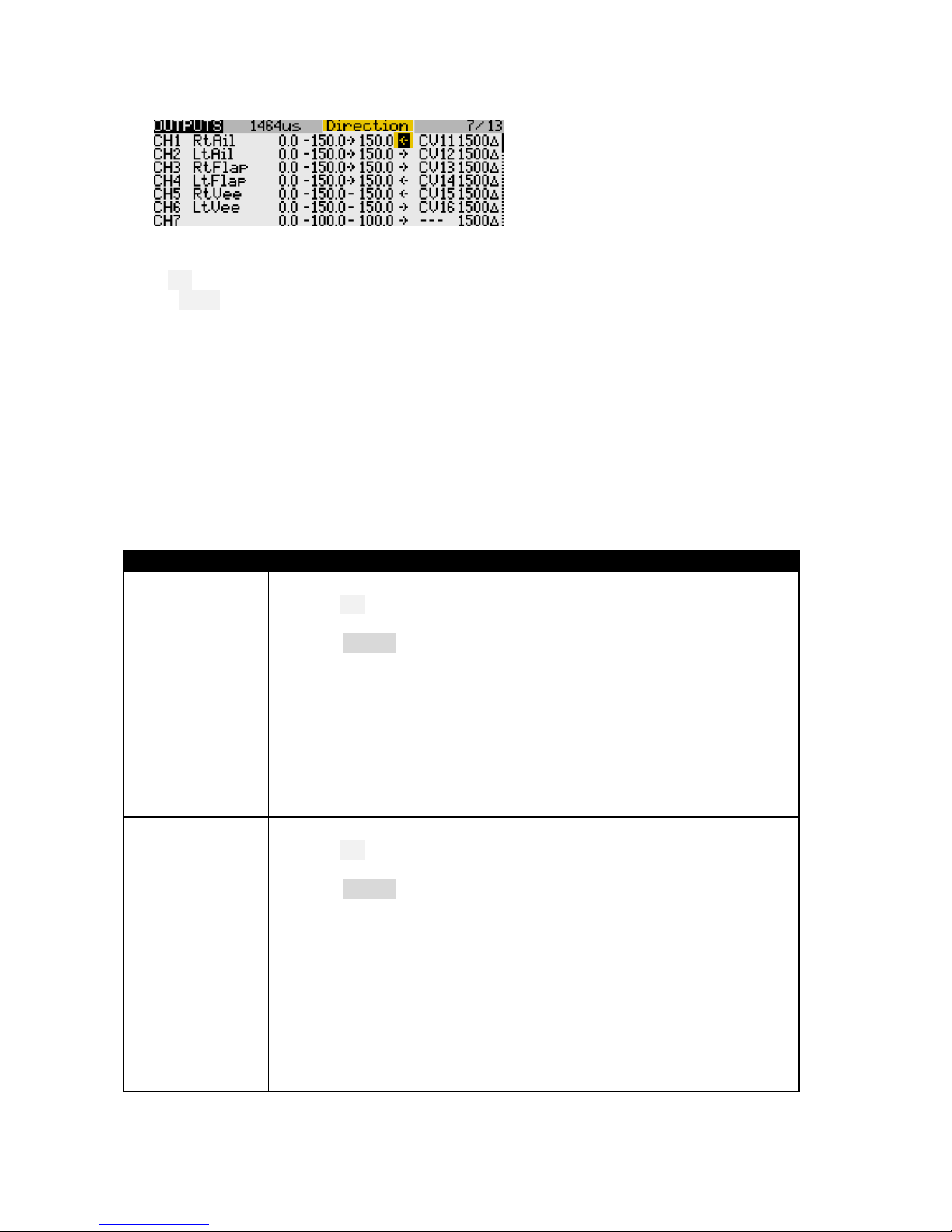
Open the OUTPUTS menu
Set the rotation of each servo according to table below:
Stick command
Control surface
Notes
Aileron stick right →
RtAil goes up ↑
LtAil goes up↑
In CAL mode, the ailerons move up
together
Thr stick forward ↑
RtFlap goes up↑
LtFlap goes up↑
V-TAIL only:
Ele stick forward ↑
RtVee goes up ↑
LtVee goes up ↑
In CAL mode, the elevator(s) operate in
reverse to normal.
X-TAIL only:
Ele stick forward ↑
Ele goes up ↑
X-TAIL only:
Rudder stick right →
Rud goes right
Page 8
Page 8 rev 3.0.03
To change the direction of an output:
1. Go to the Direction field
2. Press {ENTER}, and immediately {EXIT}
Finally, check operation as follows:
Exit CAL
Enter Cruise mode.
Check for correct direction of aileron, elevator and rudder. Note: The flaps cannot be checked yet.
6.2.2 Adjust end-points and centres
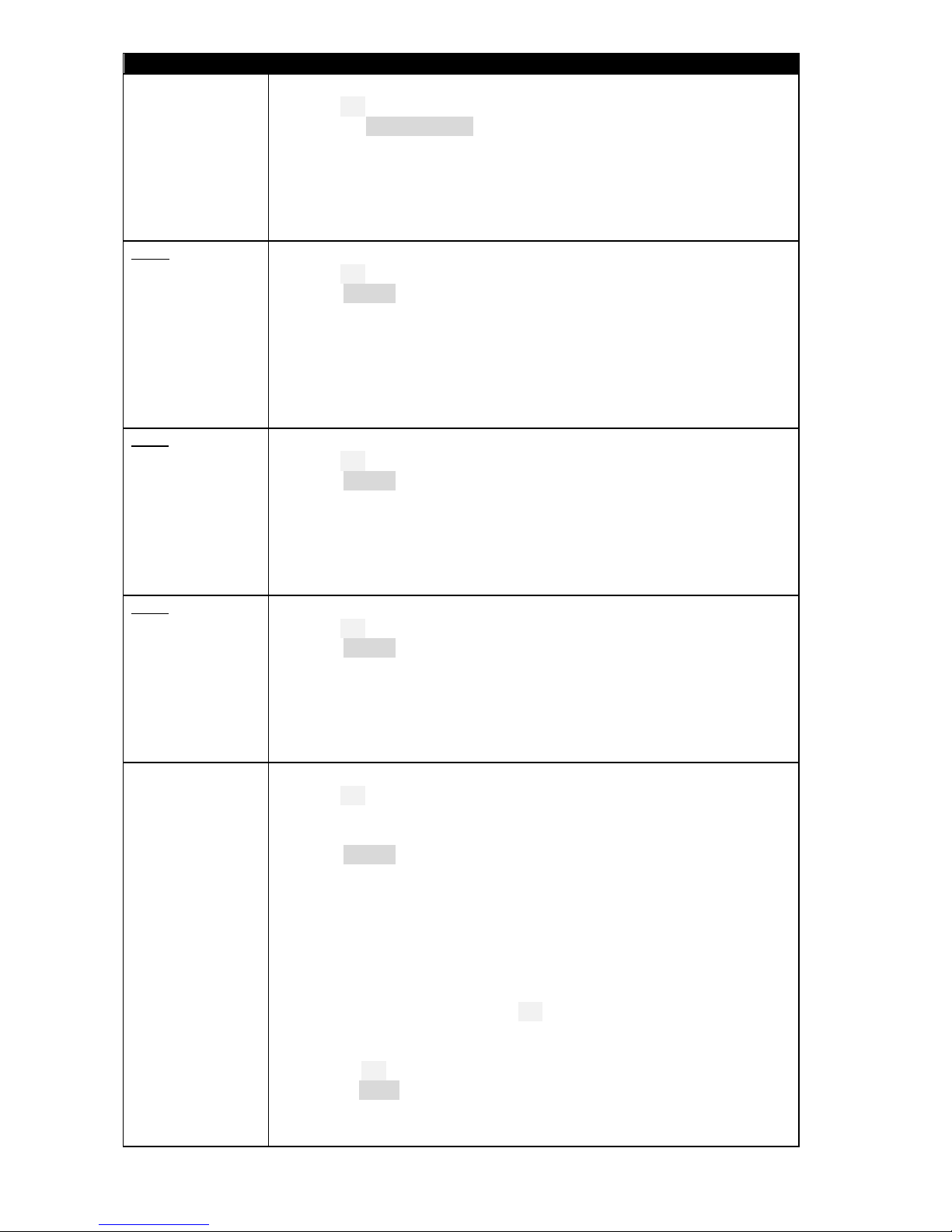
In this section you’ll adjust the servo absolute end points and centres. All adjustments are made using
curves. Do not alter min, max or subtrim.
When setting end-points, consider all the inputs. For example, when setting the flap end points, allow
sufficient travel for simultaneous crow and aileron inputs. Otherwise the flaps may stop before the
commanded position is reached, resulting in deadband at the stick (this may however be unavoidable).
If you don’t know the movements required for your model, then set servo end-points to maximum subject to
restrictions below.
Channel
Calibration procedure
CH 4 – Lt Flap
Start by calibrating the left flap.
1. Enter CAL mode
2. Switch SA to middle position
3. In the OUTPUTS menu, highlight CH4
4. Skip to curve field LtF, and press {long ENTER} to open curve editor
5. Throttle stick fully back (↓), adjust point 1 for lower end point. Allow for
both crow and aileron inputs.
6. Throttle stick fully forward (↑), adjust point 3 for upper end point. Allow
for any aileron-to-flap mixing.
7. Adjust point 2 so it lies on the straight line between points 1 and 3.
8. Move throttle stick from one end to the other, observing step intervals.
You can fine tune point 2 to equalise intervals for best linearity.
CH 3 – Rt Flap
Next, calibrate the right flap (CH3). The goal is to precisely match the left flap.
1. Enter CAL mode
2. SA to middle position
3. In the OUTPUTS menu, highlight CH3
4. Skip to curve field RtF, press {long ENTER} to open curve editor
Adjust points 1 – 5 to exactly match the left flap:
5. stick fully back, adjust point 1
6. stick ½-back, adjust point 2
7. stick to centre, adjust point 3
8. stick to ½-forward, adjust point 4
9. stick fully forward, adjust point 5
To match the end points on left and right sides, it may be necessary to reduce
one or other end points for the left flap.
Page 9
Page 9 rev 3.0.03
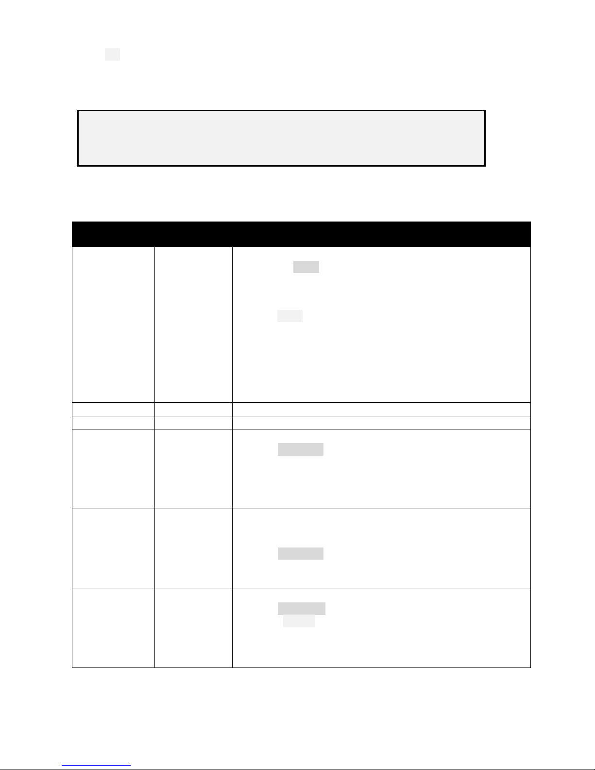
Channel
Calibration procedure
Flap offset
Next, adjust the flap offset:
1. Enter CAL mode, switch SA down.
2. Open the GLOBAL VARIABLES menu.
3. Go to FOf:FM0
4. Adjust offset so that flaps follow airfoil profile
Check that the flaps are in line with each other. If not, then redo the
calibration of the right flap (see previous step), paying particular attention to
the two points either side of the neutral position.
V-Tail
CH 5 – RtVee
CH 6 – LtVee
Calibrate V-tail surfaces:
1. Enter CAL mode
2. In the OUTPUTS menu, highlight CH5:RtVee
3. Skip to curve field ‘ERv’, press {long ENTER} to open curve editor
4. With Ele stick at centre, adjust point 2 for correct neutral
5. Ele stick forward (↑), set point 3 to upper limit
6. Ele stick back (↓), set point 1 to lower limit. Allow for crow compensation.
7. Repeat for CH6:LtVee, ensuring that movements match CH5:RtVee.
8. Check equal travel up/down; check left and right surfaces match
X-Tail
CH 5 – Ele
X-tail version only - Calibrate elevator
1. Enter CAL mode
2. In the OUTPUTS menu, highlight CH5
3. Skip to curve field ‘ERv’, press {long ENTER } to open curve editor
4. With Ele stick at centre, adjust point 2 for correct neutral
5. Move Ele stick forward (↑), then adjust point 3 for upper limit
6. Move Ele stick back (↓), then adjust point 1 for lower limit
7. Check elevator travel is equal up & down
X-Tail
CH 6 – Rudder
X- tail version only - Calibrate rudder
1. Enter CAL mode
2. In the OUTPUTS menu, highlight CH6
3. Skip to curve field ‘RLv’, press {long ENTER } to open curve editor
4. With stick in centre, adjust point 2 so rudder is central
5. Move Rudder stick right (→), then set point 3 for max right movement
6. Move Rudder stick left (←), then set point 1 for max left movement
7. Check equal travel left/right
CH 1 – Rt Ail
CH 2 – Lt Ail
Finally, calibrate ailerons:
1. Enter CAL mode
2. Set switch SA to down position. The flaps will go to their calibrated
neutrals.
3. In the OUTPUTS menu, highlight CH1:RtAil
4. Skip to curve field RtA, then press {long ENTER } to open curve editor
5. With Ail stick at centre, adjust point 2 for correct centre.
6. Move aileron stick right (), then set point 3 to desired upper limit. Allow
for both crow and aileron movement.
7. Move aileron stick left (), then set point 1 so that down-travel = up-
travel. If you cannot get sufficient down movement due to geometry, then
1. Move SA up (↑) – this reduces aileron movement by 50%. Note: this
reduced rate applies only in CAL mode!
2. Now try again: Move aileron stick left () and adjust point 1 so
down-travel = (reduced) up-travel. Full rate will be restored when you
exit CAL; don’t worry if down-travel is excessive – later adjustments in
the INPUTS menu, and to aileron diff, will reduce the movement.
8. Repeat all steps for CH2:LtAil.
9. Check: (a) equal up/down movement, (b) left and right ailerons match.
Page 10
Page 10 rev 3.0.03
Exit CAL mode
Move the sticks, checking that aileron, elevator and rudder control surfaces move in the correct sense.
Note: the flaps will cease to respond after exiting CAL mode. They will be configured in the next section.
Well done, calibration is complete! Make a backup copy of your work now.
Always do a servo CAL…
- at the start of a flying session
- after a hard landing
- after swapping out a faulty servo for a new one
7 Configuring inputs and mixers
In this last section, you’ll set the control movements and mixing.
Control / mix
Adjustment
point
Adjustment procedure
Aileron rate
INPUTSAil
Set aileron rate as follows
1. Open the INPUTS menu
2. Scroll down to [I]Ail
3. Press {long ENTER} and choose Edit
4. Skip to the weight field
5. Enter Cruise mode
6. Adjust weight for required up-aileron movement (down
movement is affected by diff setting)
7. If Expo is required, skip to Curve field, choose ‘Expo’ as the curve
type, and set required value in adjacent field.
Note: Aileron diff is set using the rudder trim; don’t use the Diff curve
type as it will result in asymmetric stick response.
Elevator rate
INPUTSEle
As above
Rudder rate
INPUTSRud
As above
Aileron→Flap
GVARS‘A2F’
Aileron to flap mixing is set per flight mode.
1. Open GLOBALVARS menu, select row ‘A2F’
2. Activate flight mode to be adjusted, the column is highlighted
3. Adjust value in highlighted column.
Note: the movement of down-going flap will be affected by diff
setting, adjusted using the rudder trim.
Ail→Rudder
GVARS‘A2R’
This mix can help smooth turns without the need to coordinate
rudder and aileron controls.
Adjust per flight mode as follows:
1. Open GLOBALVARS menu, select row ‘A2R’
2. Activate flight mode to be adjusted - the column is highlighted
3. Adjust value in highlighted column
CrowAil
GVARS‘CmA’
Sets the upward aileron movement due to crow.
1. Open GLOBALVARS menu
2. Enable Landing mode
3. Go to CmA:FM3
4. Move throttle stick back (full crow)
5. Adjust value for required up-aileron movement
Page 11
Page 11 rev 3.0.03
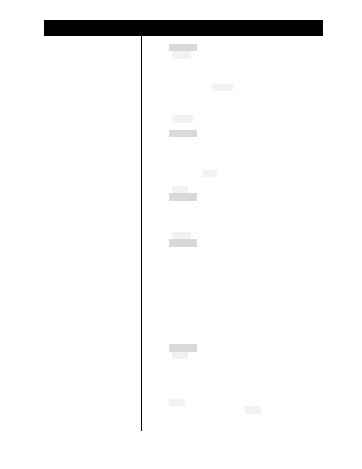
Control / mix
Adjustment
point
Adjustment procedure
CrowFlap
GVARS ‘CmF’
Sets the downward flap movement due to crow.
1. Open GLOBALVARS menu
2. Enable Landing mode
3. Go to CmF:FM3
4. Move throttle stick back (full crow)
5. Adjust value for required down-flap movement
CamberAil
CamberFlap
GVARS ‘CmA’
GVARS ‘CmF’
Camber can be adjusted in Thermal mode using lever RS. Adjustment
range = +/- 50%. For example if nominal camber is 4 degrees (RS at
centre), the range will be from 2 to 6 degrees.
In this step, you will set nominal camber. Start with flaps:
1. Enable Thermal mode
2. Move RS to centre position.
3. Open GLOBALVARS menu
4. Go to CmF:FM0
5. Adjust flap camber as required
For ailerons, repeat above using CmA:FM0
Check camber range by moving RS forward and back.
ReflexAil
ReflexFlap
GVARS’CmA’
GVARS’CmF’
Reflex can be preset in Speed mode (FM5).
Start with flaps:
1. Enable Speed mode
2. Open GLOBALVARS menu
3. Adjust reflex in CmF:FM5
Repeat for ailerons using CmA: FM5
Reverse diff
GVARS ‘RvD’
Reverse diff can improve roll response under braking, by increasing
movement of down-going aileron.
1. Enable Landing mode
2. Open GLOBALVARS menu
3. Go to RvD: FM3
4. Apply full crow and full aileron
5. Adjust value so that the down-going aileron is at the desired
position (normally a little below the neutral position)
Note: this measure for improving roll response is in addition to aileron
diff suppression, which is automatically applied.
MotorEle
compensation
GVARS ‘Cmp’
Motor compensation counteracts pitch changes due to motor thrust.
It is adjustable in flight via the thr trim:
Trim forward → pitch down
Trim centre → zero compensation
Trim back → pitch up
Make sure the motor is disconnected while configuring.
1. Open GLOBALVARS menu, highlight Cmp:FM2
2. Enable Power mode
3. Push LS fully forward (max motor)
4. Move throttle trim fully forward (max down comp)
5. Adjust Cmp:FM2 for required max down compensation
6. Move throttle trim to centre prior to flight tests
During test flights:
1. Enter Power mode.
2. Apply minimum power (while still in Power mode), and adjust
elevator trim for level flight.
3. Apply full power and adjust throttle trim for level flight.
Page 12
Page 12 rev 3.0.03
Control / mix
Adjustment
point
Adjustment procedure
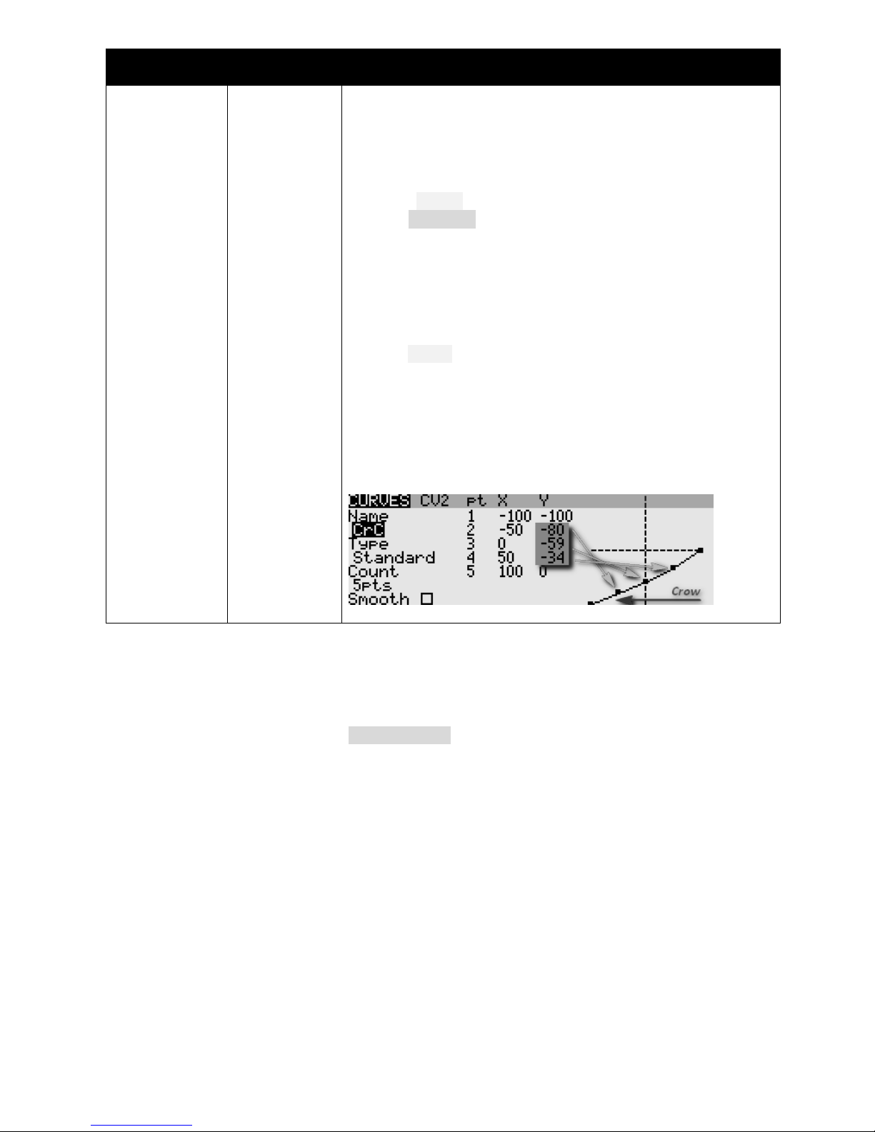
CrowEle
compensation
GVARS ‘Cmp’
Crow compensation is used to counteract pitch changes as crow is
applied. It can be fine tuned in flight using the throttle trim.
Trim fully back = zero compensation
Trim forward = down compensation
First, set the limit of adjustment:
1. Enable Landing mode.
2. Open GLOBALVARS menu, highlight Cmp:FM3
3. Apply maximum crow
4. Move throttle trim fully forward for max compensation
5. Adjust Cmp:FM3 to set limit of compensation.
6. Move throttle trim to recommended compensation. If not known,
set trim fully back (zero comp).
During flight tests, adjust pitch trim as follows:
1. Enter landing mode
2. Apply minimum crow, then adjust elevator trim.
3. Apply full crow, adjust throttle trim.
Note: After intial flight tests, you can fine-tune the response by editing
curve ‘CrC’. Alter points 2-4 only. Figure shows compensation rising
sharply on initial application of crow, then tailing off towards the
maximum (as defined by the throttle trim setting).
8 Motor safety check
One final safety check.
With the motor disconnected, Enter CHANNEL MONITOR menu:
Taranis: Opening screen, then press {PAGE}x3
Horus: Opening screen, press {MDL}x2
Check for correct behaviour of the motor channel (CH7:Motor). Practice arming, disarming and applying
throttle. Check motor-off = -100, full power = +100.
Congratulations, you’ve finished setting up your model! Just one last thing….
Back up your EEPROM now!
Page 13
Page 13 rev 3.0.03
9 Summary of in-flight adjusters
Target
Adjuster
Flight mode
Notes
Aileron Diff
Rudder trim
[Any]
Diff is stored per flight mode
Default range is 0 - 70%
Trim centre corresponds to 35% diff
CrowEle compensation
Throttle trim
Landing
Adjust compensation with full crow deployed
Trim fully back → zero comp
MotorEle compensation
Throttle trim
Power
Adjust compensation with motor at full power
Trim in centre → zero comp
Aileron Trim
Aileron trim
[All]
Aileron trim can be adjusted in any flight mode
but is global, i.e. the same trim value is shared
by all flight modes.
Elevator trim
Elevator trim
[Any]
Elevator trim is stored per flight mode
10 Pre-flight
Before using this setup for the first time, remember to:
Train your ESC to recognise the motor off/on commands – consult your ESC documentation.
Set the battery alarm threshold to suit your battery chemistry, for both the tx and rx.
Set the failsafe so that the motor channel (CH7:Motor) is -100 on loss of signal.
11 Customisations
This section describes various simple customisations. Apply these after the basic setup is complete and
backed up. Customisations will not affect mixer adjustments, so you can customise at any time without
breaking the setup.
11.1 Changing the assignments of Crow, Motor and Camber
Crow, motor and camber functions may be assigned to any suitable control. Recommended options for the
Taranis X9D are as follows:
Function
Assign to
Default
Menu point
Crow
Thr, LS, or RS
Thr
MixersCH17:RawCro
Motor
Thr, LS, RS, or 3p switch
LS
MixersCH18:RawMot
Camber
Thr, LS, RS, or 3p switch
RS
MixersCH20:Camber
11.2 Changing the flight mode switch
By default, the main flight mode switch is SA. You can specify another switch Sw instead, as follows:
1. Choose Sw from any 3-position switch (for X9D these are SA, SB, SC, SD, SE or SG).
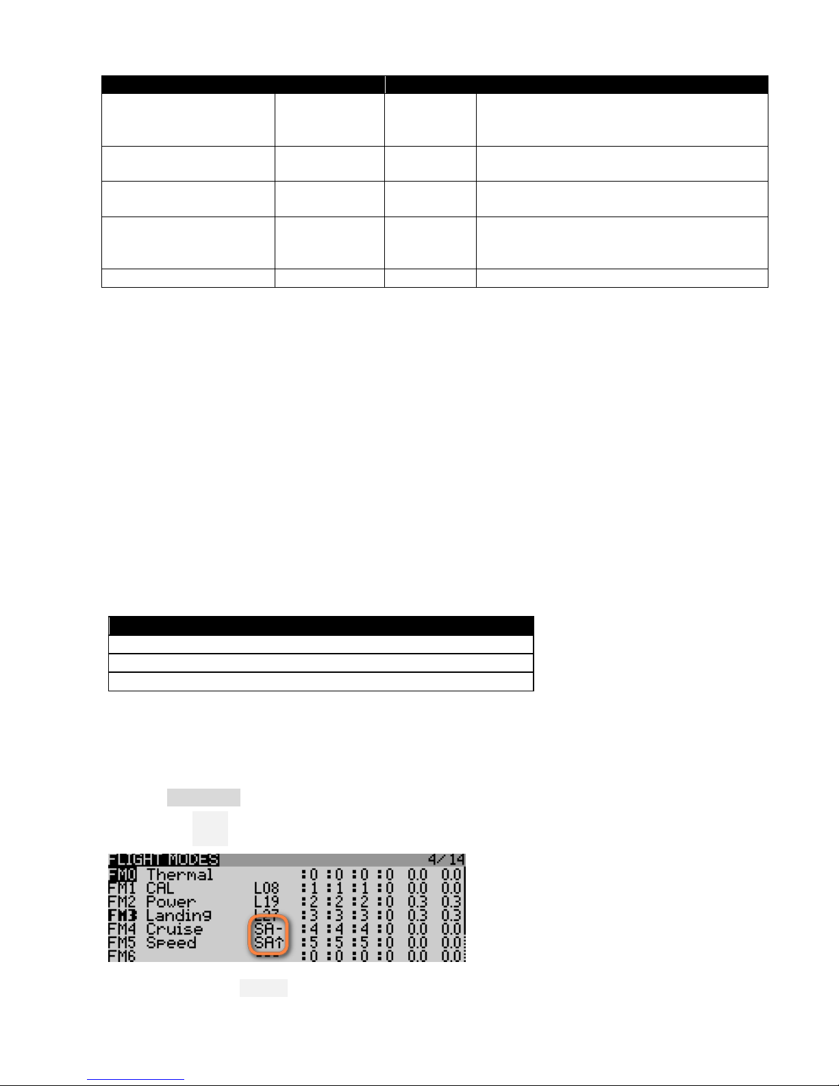
2. In the FLIGHT MODES menu, set the switches as follows:
FM4 (Cruise): Sw―
FM5 (Speed): Sw↑
Note: Sw↓ will select Thermal mode (you don’t set this explicitly).
Page 14
Page 14 rev 3.0.03
11.3 Reversing the crow stick
By default, zero crow corresponds to throttle stick fully-forward. To reverse the behaviour:
1. Open the MIXERS menu
2. Skip down to CH17:RawCro
3. Open the mixer editor
4. Change the curve from ‘CCt’ to ‘!CCt’ (note leading exclamation mark).
11.4 Reversing motor lever
By default, motor off (idle) corresponds to LS fully back. To alter so that motor off is with LS fully forward:
1. Open the MIXERS menu
2. Skip down to CH18:RawMot
3. Open the mixer editor
4. Change the curve from ‘MCt’ to ‘!MCt’ (note leading exclamation mark).
Note: this alters the direction of the motor lever only. The idle and full power commands sent to the motor
are unchanged.
11.5 Reversing camber lever
To reverse the direction of the camber laver
1. Open the MIXERS menu
2. Skip to CH20:Camber
3. Change weight from +25 to -25
11.6 Dual rates
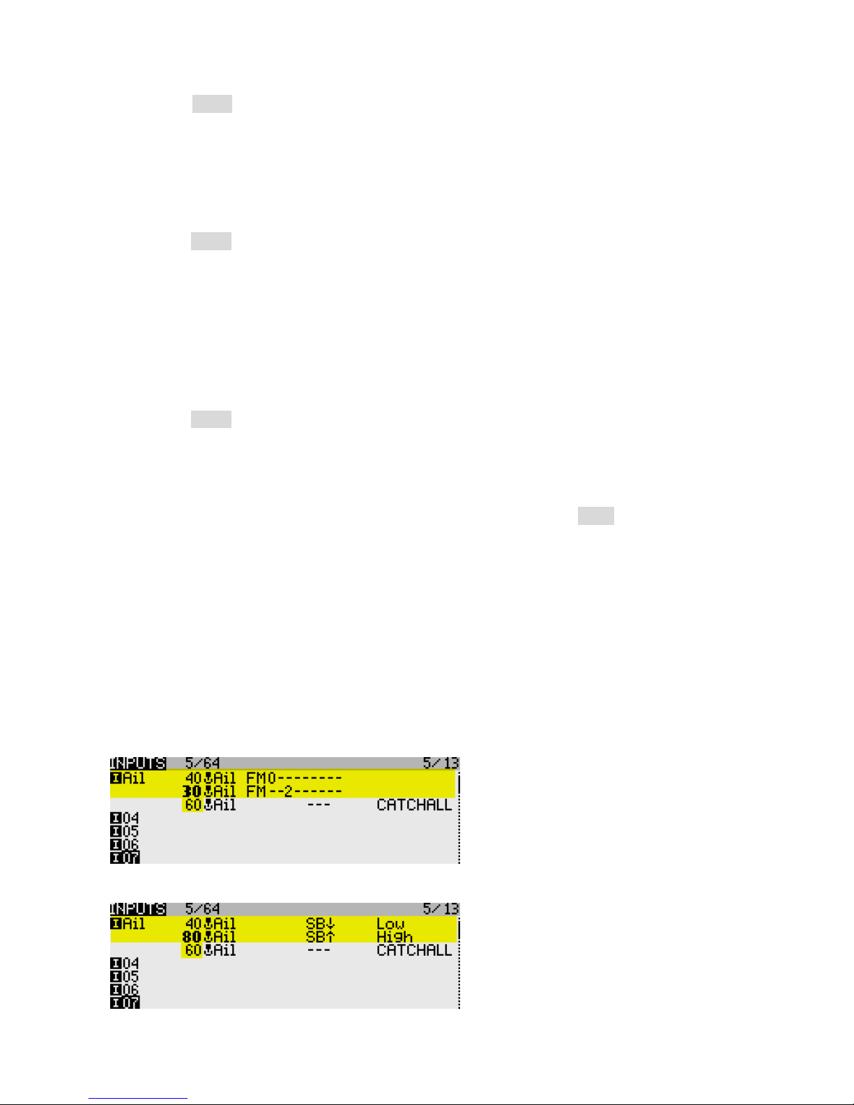
There is no dedicated rates menu in OpenTx. Instead, you add extra lines in the INPUTS menu.
For each new rate, create an input, and tick the applicable flight modes, alternatively you can specify a
switch. Flight mode numbers as follows:
0: Thermal
2: Power
3: Landing
4: Cruise
5: Speed
Safety note: The last input must be a ‘catchall’ with all flight modes enabled, and no switch. This ensures
that the control will be active even if no other line is selected.
Below are examples showing triple rates (a) linked to flight-modes and (b) selected by switch:
(a) Aileron rate by flightmode: Thermal (FM0) 40%; Power mode (FM2) 30%; all other flight modes: 60%
(b) Aileron rate by switch: SB↓ 40%; SB↑80%; default (SB― ): 60%
Page 15
Page 15 rev 3.0.03
How OpenTx handles inputs: Starting with the first Input line, OpenTx reads the flight mode and/or switch. If these
correspond to the actual FM and switch states, OpenTx uses the rate and expo values specified in that line.
If there is no match, OpenTx advances to the next line and repeats the test. The cycle is repeated until either a match
is found or the end of the input list is reached. If no match is found in any line, the control will be inoperative. As a
defence against this possibility, the last line must be a ‘CATCHALL’ with all flightmodes checked and no switch.
If both flightmode and switch are specified in the same line, both must match for the line to be active.
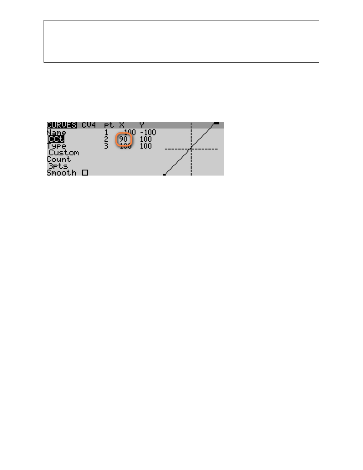
11.7 Adjusting crow stick deadband
The crow stick response incorporates some deadband at the idle end to help prevent accidental
deployment. The default value should be fine for most pilots; however it can be adjusted as follows:
1. Go to Curves menu
2. Open Curve4:CCt
3. Adjust pt2 -> X. Decrease value to increase the deadband. Default value is 90.
11.8 Selecting an alternative arming method
New in version 3 is the ability to select between three different arming/disarming methods. Selection is by
altering the first parameter of logical switches L4 and L5. You can also choose which switch to use. Safety
note: If you’re not 100% confident with data entry, then stick with the default setup.
11.8.1 Method 1(default): stick in corner, pull SH
To arm: motor lever off. Full back on elevator stick, full right aileron, pull SH and hold until confirmation
To disarm: pull SH until disarm confirmation
This method is the default, and it works like previous versions of ESP. It is the most secure method, and is
recommended for beginners and sport flyers.
Settings: L4: V1 = L30
L5: V1 = L31
L2: V1= spring switch↓. Safety note: use a spring switch only (not a regular 2- or 3-p switch).
11.8.2 Method 2: Pull SH
To arm: motor lever off. Pull SH until arming confirmation
To disarm: pull SH until disarming confirmation
This method is better suited if you need to disarm and re-arm in flight.
Settings: L4: V1 = L35
L5: V1 = L36
L2: V1= spring switch↓. Safety note: use a spring switch only (not a regular 2- or 3-p switch).
11.8.3 Method 3: Two-position switch
To arm: motor lever off, SF down.
To disarm: SF up
This method offers fast arming/disarming whether on the ground on in the air. At startup, the motor will be
disarmed irrespective of the position of SF, so switch checks are not required. This method is inherently
less secure than the first two, and is for experienced flyers only.
Settings: L4: V1 = L38
L5: V1 = L39
L3: V1= 2- or 3-pos switch. Default is SF↓
Page 16

Page 16 rev 3.0.03
12 Making your own mods
If you wish to make your own modifications, please study the Excel documentation carefully and make sure
you understand the implications of any changes. Recommended workflow as follows:
1. Setup your model as described in this manual
2. Backup your work
3. Apply your modifications incrementally, testing and backing up as you go along.
13 Disclaimer
Although this setup is tested, it’s up to the pilot to make sure that the controls respond correctly under all
conditions. The author will not be responsible for the consequences of any bugs in the setup or
documentation or as the result of changes in OpenTx.
Remember to test your setup thoroughly before the
first flight and after any modifications!
If in doubt, don’t fly!!
14 Contact
If you have any queries or suggestions, or if you find any errors in the documentation, or just want to say
hello, then please contact me at http://rc-soar.com/email.htm.
Safe flying!
Mike Shellim
 Loading...