

Tarana Wireless AA25G User Manual
leading
The
Manual
Quick-Start Guide
The essentials of getting a link up and running
Tarana Wireless, Inc. Proprietary, Confidential, and ©2016. All rights reserved. vAA2-2016-04 Quick Start — 1
Preparation
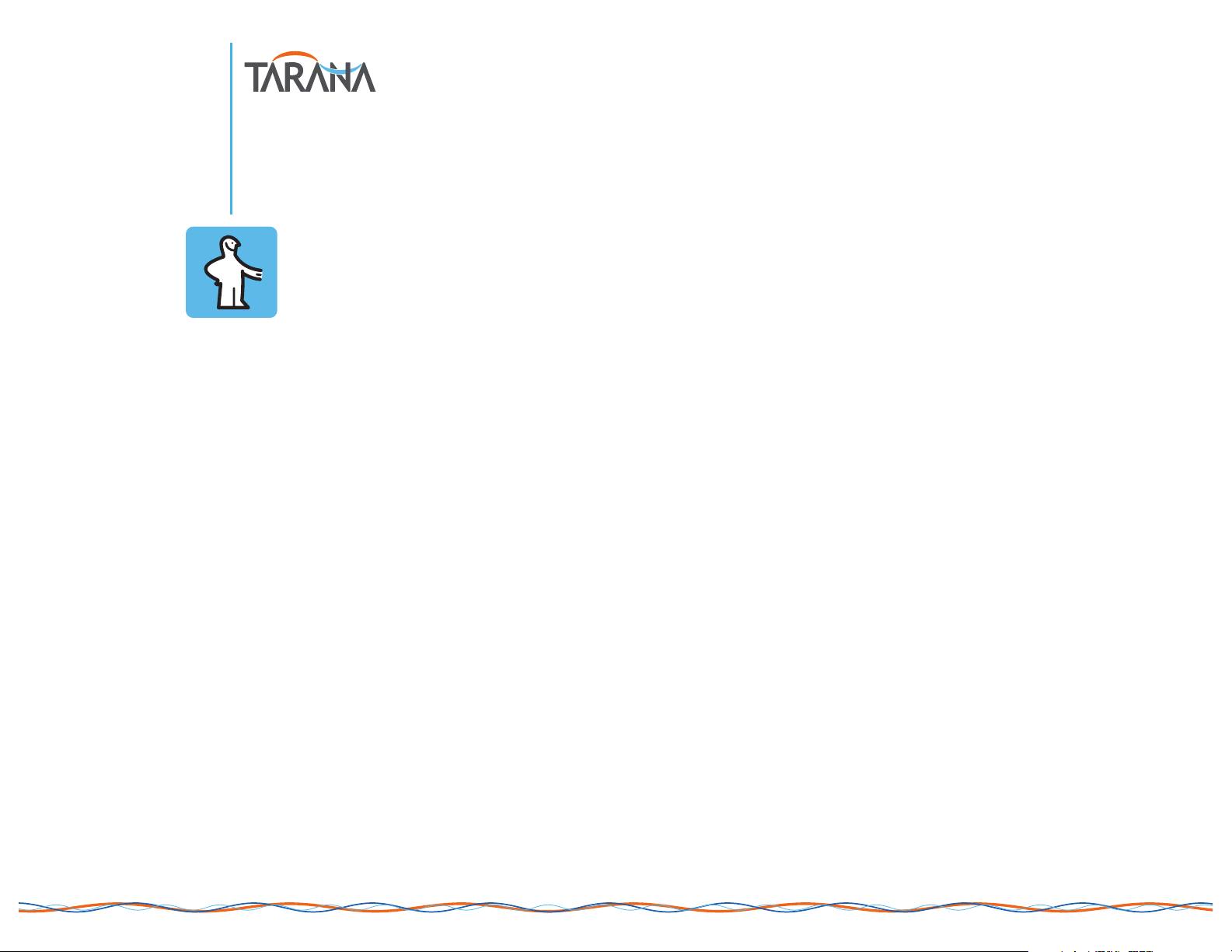
Setting up a Tarana Wireless® link requires gathering, at a minimum, the following:
Tools
13 mm combination or socket wrench
5 mm hex driver or wrench
T30 Torx driver
Wi-Fi USB dongle and short USB extension cable
mobile device for setup and alignment (smartphone, tablet, or laptop) with
terminal app and current browser
Hardware
1 CN and 1 EN radio unit
2 elevation-adjust mounting bracket kits
2 pole/wall mounting kits
2 power sources and cables
2 Ethernet cables (+ SFPs, if fiber)
2 target mounting locations (wall or pole)
Information
frequency of operation
Transmit (Tx) power limit
link code
2 IP addresses (if not DHCP)
Regulatory, Safety, and Best Practices
Tarana AbsoluteAir® equipment is designed for installation and use by trained
professionals and requires adherence to all relevant regulatory, safety, and telecom
industry best practice guidelines for outdoor radios. See our Safety, Warnings, and
Regulatory section for details.
Power and Connectivity Sources
CN or
EN Unit
Elevation-Adjust
Bracket Kit
Power and
Ethernet
Cable(s)
Wi-Fi
Dongle
Mobile Device for
Config, Alignment,
and Verification
Pole/Wall Mounting Kit
Essentials of a Tarana Link Installation
Tarana Wireless, Inc. Proprietary, Confidential, and ©2016. All rights reserved. vAA2-2016-04 Quick Start — 2
Sequence
For a single point-to-point link, the EN and CN can be installed in whichever order is most convenient. Otherwise, CNs should be installed before ENs, as the latter have more
alignment flexibility when multiple links are involved that can be leveraged to maximize link headroom and resilience.
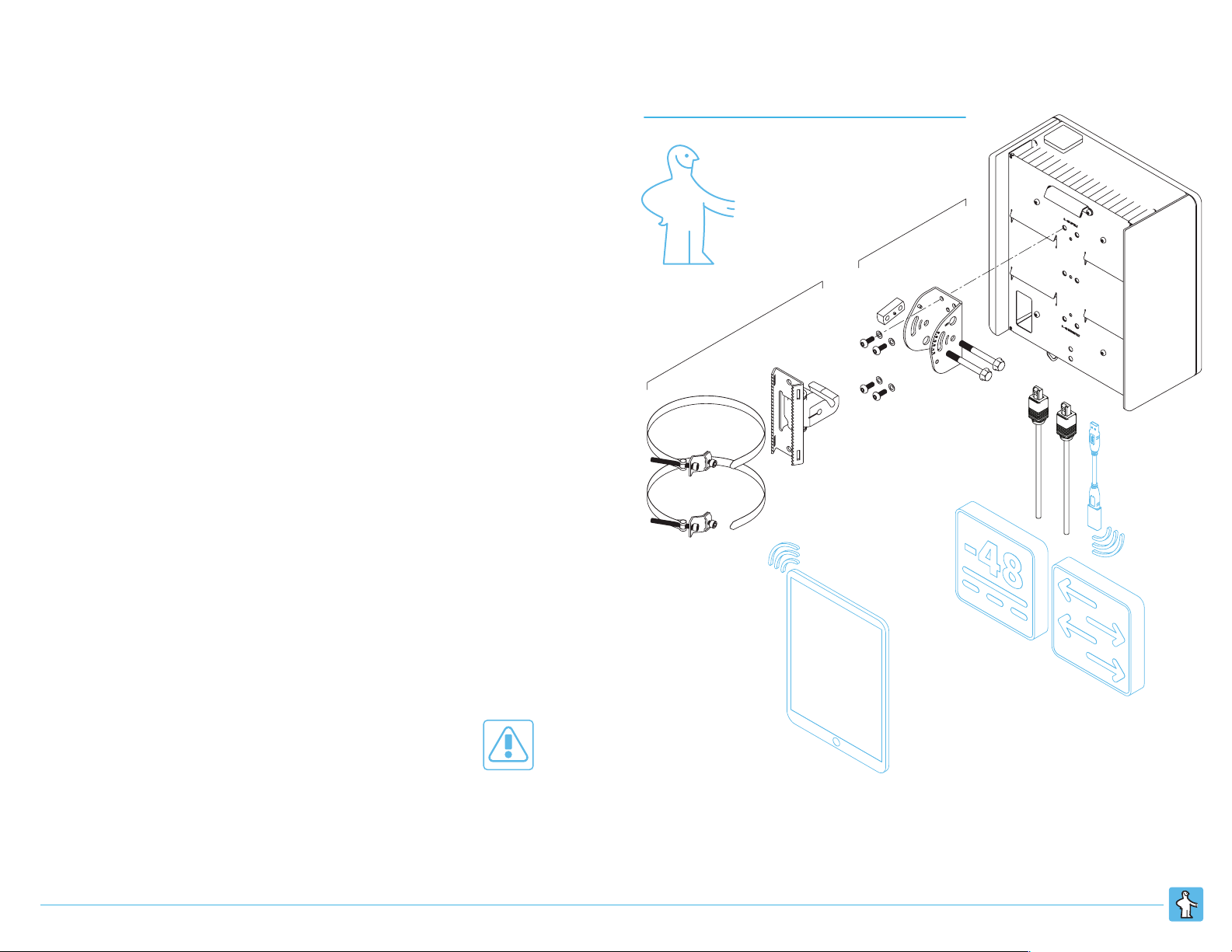
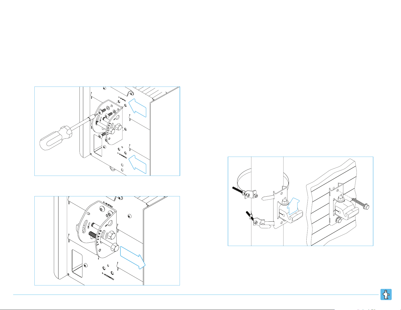
Physical Installation
Step 1. Attach elevation-adjust bracket to rear of unit. Torque these screws to 42-
60 in-lb (5-7 Nm). Note uptilt v. downtilt position options, used typically for
ENs and CNs, respectively.
Step 2. Remove outer M8x70 hex/flange bolt from elevation-adjust bracket.
Step 3. Attach assembled gimbal and mounting bracket with groove opening in
gimbal facing up. Do not torque the azimuth adjustment bolt at this time,
as you may want to adjust the angle as part of link alignment. After
alignment is complete, torque to 25 ft-lb (33 Nm).
For wall mounting, use fasteners appropriate to wall material. A load rating
of 220 lbs. is recommended per fastener.
For pole mounting, insert the band through the slot under the hex-head
locking bolt. Pull the band through the slot until nearly tight, then fold over
the band at the edge of the locking bolt/slot. Torque the locking bolt to 4244 in-lb (4.75-5 Nm). Clip off excess band if required. Partially tighten the
tension bolt to secure to the pole. Do not torque the bolt at this time, as
you may want to adjust the position as part of link alignment. After
alignment is complete, torque the tension bolt to 70-75 in-lb (8-8.5 Nm).
Up
Down
Remove
Up
Gimbal

Tarana Wireless, Inc. Proprietary, Confidential, and ©2016. All rights reserved. vAA2-2016-04 Quick Start — 3
Step 4. Hang unit on gimbal, hooking inner hex/flange bolt into groove.
Step 5. Return outer hex/flange bolt to bracket, orient unit, and tighten. Do not
torque the bolt at this time, as you may want to adjust the angle as part of
link alignment. After alignment is complete, torque to 25 ft-lb (33 Nm).

Tarana Wireless, Inc. Proprietary, Confidential, and ©2016. All rights reserved. vAA2-2016-04 Quick Start — 4
Ground
1 2 3 4 5 6
Ground
1 2 3 5 6
Power and Connectivity
Supply -48 VDC to the unit through either its power port (1) or PoE-in enabled
Ethernet port (2). Ethernet connectivity can be established for link and
management traffic in a variety of configurations using the three or four Ethernet
ports — see our Configuration section for more details. Absent other network
design constraints or goals, a single ETH<n> port can be used for both, separating
traffic with VLANs. In any configuration, all power and signal cables must be
terminated with Harting weatherproof connectors. Proper lightning or surge
suppression devices and associated grounding are required for all connections.
Grounding
Install the ground wire prior to hanging the unit on the gimbal, as the pole or wall
may block access to the ground port. Ground the unit by attaching the grounding
wire via a standard barrel copper lug (PN#48-0061-001). Use an M8-1 X 10MM panhead screw and appropriate locking hardware (lock washers or thread-locker
adhesive) to secure the lug to the unit. Ensure the grounding wire is attached to
earth ground in accordance with local electrical code requirements.
Interfaces
Port
Description
1
Dedicated -48 VDC input, from AC adapter or other site power source
2
1000BASE-T, RJ45, with PoE-in option for powering unit
3
1000BASE-T, RJ45
4
(CN only) 1000BASE-T, RJ45, dedicated management interface
5
SFP socket (1000BASE-X fiber or 1000BASE-T copper)
6
USB-A for direct management access during installation or
maintenance via Wi-Fi or Ethernet dongle
CN and EN Power, Data, and Management Interfaces
 Loading...