

Tappan TMV151FBA, TMV151FSA Installation Guide
Installation Instructions
Over the Range Microwave Oven
BEFORE YOU BEGIN
Read these instructions completely and carefully.
• IMPORTANT - Save these instructions for
local inspector's use.
• IMPORTANT-observe all governing codes
and ordinances.
• Note to Installer- Be sure to leave these
instructions with the Consumer.
• Note to Consumer- Keep these instructions for
future reference.
• Skill level - Installation of this appliance requires
basic mechanical and electrical skills.
• Proper installation is the responsibility of the
installer.
• Product failure due to improper installation is not
covered under the Warranty.
READ CAREFULLY. KEEP THESE INSTRUCTIONS.
CONTENTS
irlS[alla[iorl irlstrucuorl_5
General information
Important Safety Instructions ..................... 3
Electrical Requirements .............................. 3
Hood Exhaust ........................................... 4, 5
Damage - Shipment/Installation ................. 6
Parts Included ............................................... 6
Tools You Will Need ..................................... 7
Mounting Space ............................................ 7
Step-by-step installation guide
Placement of Mounting Plate ................ 8-10
Removing the Mounting Plate ................... 8
Finding the Wall Studs .............................. 8
Determining Wall Plate Location ............... 9
Aligning the Wall Plate ............................ 10
C
Outside Back Exhaust ............................. 18-21
Preparing Rear Wall ................................ 18
Attach Mounting Plate to Wall ........... 18, 19
Preparation of Top Cabinet ..................... 19
Adjust Blower .................................... 19, 20
Mount the Microwave Oven ............... 20, 21
Before You Use Your Microwave .............. 22
Installation Types ................................. 11-21
A Recirculating ........................................... 12-13
Attach Mounting Plate to Wall ................. 12
Preparation of Top Cabinet ..................... 12
Mount the Microwave Oven ..................... 13
B
Outside Top Exhaust .............................. 14-17
Attach Mounting Plate to Wall ................. 14
Preparation of Top Cabinet ..................... 15
Adjust Blower .................................... 15, 16
Check Damper Operation ........................ 16
Mount Microwave Oven ........................... 16
Adjust Exhaust Adaptor ........................... 17
Connecting Ductwork .............................. 17
irlS[alla[iorl irlstrucuorl_5
IMPORTANT SAFETY INSTRUCTIONS
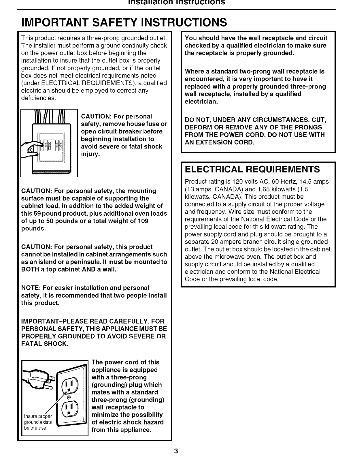
This product requires a three-prong grounded outlet.
The installer must perform a ground continuity check
on the power outlet box before beginning the
installation to insure that the outlet box is properly
grounded. If not properly grounded, or if the outlet
box does not meet electrical requirements noted
(under ELECTRICAL REQUIREMENTS), a qualified
electrician should be employed to correct any
deficiencies.
CAUTION: For personal
safety, remove house fuse or
open circuit breaker before
beginning installation to
avoid severe or fatal shock
injury.
CAUTION: For personal safety, the mounting
surface must be capable of supporting the
cabinet load, in addition to the added weight of
this 59 pound product, plus additional oven loads
of up to 50 pounds or a total weight of 109
pounds.
CAUTION: For personal safety, this product
cannot be installed in cabinet arrangements such
as an island ora peninsula. It must be mounted to
BOTH a top cabinet AND a wall.
NOTE: For easier installation and personal
safety, it is recommended that two people install
this product.
You should have the wall receptacle and circuit
checked by a qualified electrician to make sure
the receptacle is properly grounded.
Where a standard two-prong wall receptacle is
encountered, it is very important to have it
replaced with a properly grounded three-prong
wall receptacle, installed by a qualified
electrician.
DO NOT, UNDER ANY CIRCUMSTANCES, CUT,
DEFORM OR REMOVE ANY OF THE PRONGS
FROM THE POWER CORD. DO NOT USE WITH
AN EXTENSION CORD.
ELECTRICAL REQUIREMENTS
Product rating is 120 volts AC, 60 Hertz, 14.5 amps
(13 amps, CANADA) and 1.65 kilowatts (1.5
kilowatts, CANADA). This product must be
connected to a supply circuit of the proper voltage
and frequency. Wire size must conform to the
requirements of the National Electrical Code or the
prevailing local code for this kilowatt rating. The
power supply cord and plug should be brought to a
separate 20 ampere branch circuit single grounded
outlet. The outlet box should be located in the cabinet
above the microwave oven. The outlet box and
supply circuit should be installed by a qualified
electrician and conform to the National Electrical
Code or the prevailing local code.
IMPORTANT-PLEASE READ CAREFULLY. FOR
PERSONAL SAFETY, THIS APPLIANCE MUST BE
PROPERLY GROUNDED TO AVOID SEVERE OR
FATAL SHOCK.
The power cord of this
appliance is equipped
with a three-prong
(grounding) plug which
mates with a standard
three-prong (grounding)
wall receptacle to
Insure proper
ground exists
before use
minimize the possibility
of electric shock hazard
from this appliance.
irlS[alla[iorl irlstrucuorl_5
HOOD EXHAUST
NOTE: Read these next two pages only if you plan to vent your exhaust to the outside. If you plan to
recirculate the air back into the room, proceed to page 11.
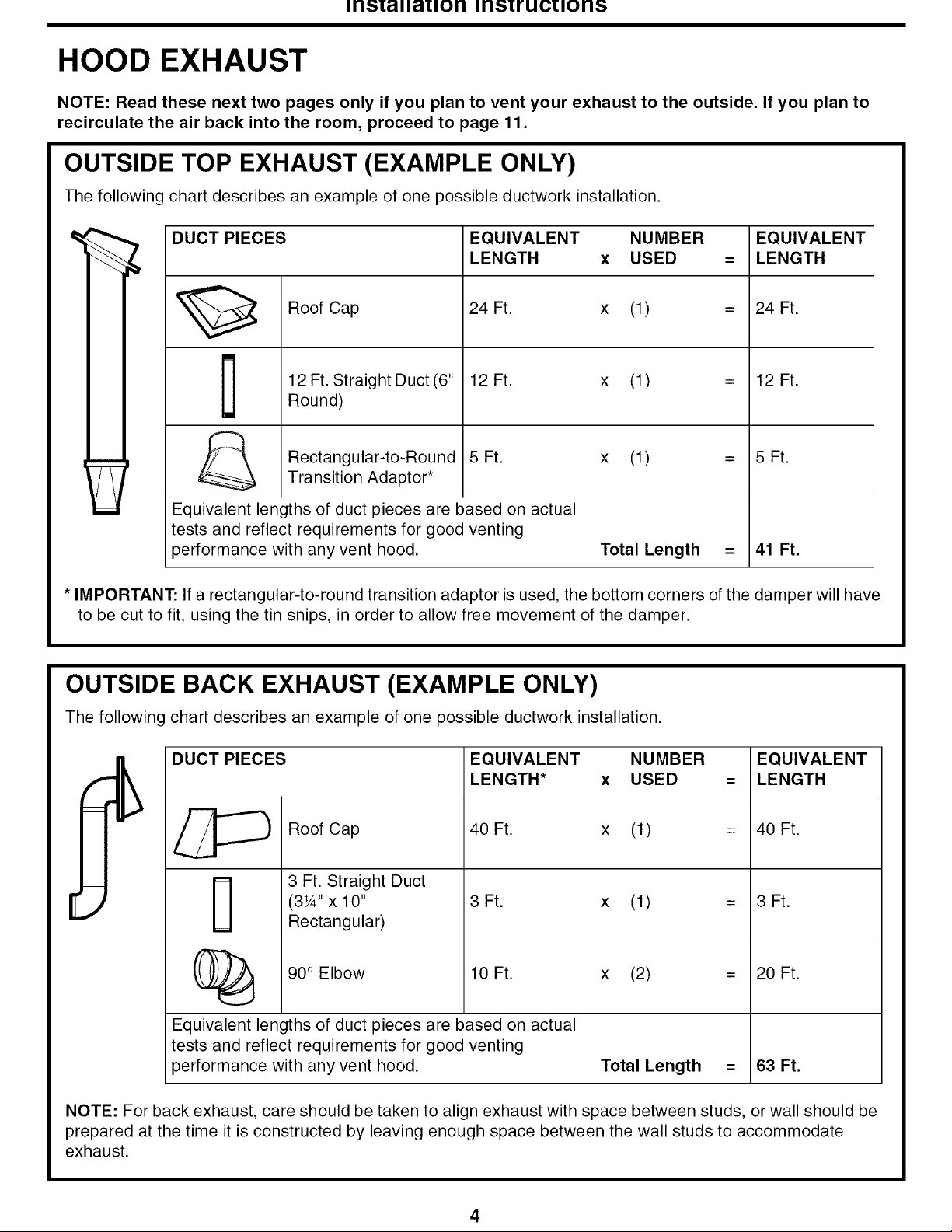
OUTSIDE TOP EXHAUST (EXAMPLE ONLY)
The following chart describes an example of one possible ductwork installation.
DUCT PIECES
Roof Cap
12 Ft. Straight Duct (6"
[]
Equivalent lengths of duct pieces are based on actual
tests and reflect requirements for good venting
performance with any vent hood.
* IMPORTANT: If a rectangular-to-round transition adaptor is used, the bottom corners of the damper will have
to be cut to fit, using the tin snips, in order to allow free movement of the damper.
Round)
Rectangular-to-Round 5 Ft.
Transition Adaptor*
EQUIVALENT NUMBER
LENGTH x USED
24 Ft. x (1)
12 Ft. x (1)
x (1)
Total Length
EQUIVALENT
= LENGTH
= 24 Ft.
= 12 Ft.
= 5 Ft.
= 41 Ft.
OUTSIDE BACK EXHAUST (EXAMPLE ONLY)
The following chart describes an example of one possible ductwork installation.
DUCT PIECES
Roof Cap
3 Ft. Straight Duct
(3¼"x 10"
Rectangular)
(_ 90 ° Elbow 10 Ft.
Equivalent lengths of duct pieces are based on actual
tests and reflect requirements for good venting
performance with any vent hood.
NOTE: For back exhaust, care should be taken to align exhaust with space between studs, or wall should be
prepared at the time it is constructed by leaving enough space between the wall studs to accommodate
exhaust.
EQUIVALENT NUMBER
LENGTH* x USED
40 Ft. x (1)
3Ft. x (1)
x (2)
Total Length
EQUIVALENT
= LENGTH
= 4O Ft.
= 3 Ft.
= 2O Ft.
= 63 Ft.
irlS[alla[iorl irlstrucuorl_5
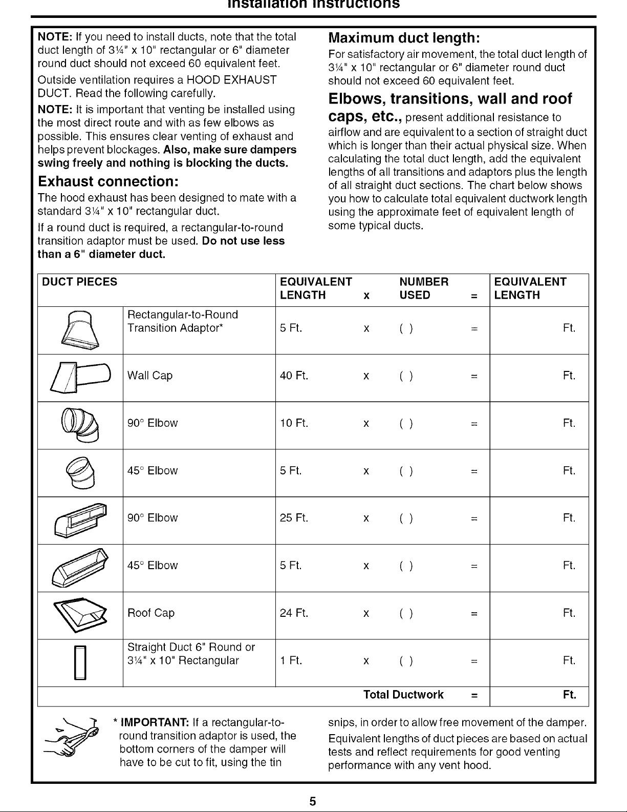
NOTE: If you need to install ducts, note that the total
duct length of 3¼" x 10" rectangular or 6" diameter
round duct should not exceed 60 equivalent feet.
Outside ventilation requires a HOOD EXHAUST
DUCT. Read the following carefully.
NOTE: It is important that venting be installed using
the most direct route and with as few elbows as
)ossible. This ensures clear venting of exhaust and
helps prevent blockages. Also, make sure dampers
swing freely and nothing is blocking the ducts.
Exhaust connection:
The hood exhaust has been designed to mate with a
standard 3¼"x 10" rectangular duct.
If a round duct is required, a rectangular-to-round
transition adaptor must be used. Do not use less
than a 6" diameter duct.
DUCT PIECES EQUIVALENT NUMBER EQUIVALENT
LENGTH x USED = LENGTH
Transition Adaptor* 5 Ft. x ( ) = Ft.
Rectangular-to-Round
Maximum duct length"
For satisfactory air movement, the total duct length of
3¼" x 10" rectangular or 6" diameter round duct
should not exceed 60 equivalent feet.
Elbows, transitions, wall and roof
caps, etc., present additional resistance to
airflow and are equivalent to a section of straight duct
which is longer than their actual physical size. When
calculating the total duct length, add the equivalent
lengths of all transitions and adaptors plus the length
of all straight duct sections. The chart below shows
you how to calculate total equivalent ductwork length
using the approximate feet of equivalent length of
some typical ducts.
_ Wall Cap 40 Ft. x ( ) = Ft.
(_ 90° Elbow 10 Ft. x ( ) = Ft.
(_ 45 ° Elbow 5 Ft. x ( ) = Ft.
90 ° Elbow 25 Ft. x ( ) = Ft.
45 ° Elbow 5 Ft. x ( ) = Ft.
Roof Cap 24 Ft. x ( ) = Ft.
-- Straight Duct 6" Round or
3¼"x 10" Rectangular 1 Ft. x ( ) = Ft.
* IMPORTANT: If a rectangular-to-
round transition adaptor is used, the
bottom corners of the damper will
have to be cut to fit, using the tin
Total Ductwork = Ft.
snips, in order to allow free movement of the damper.
Equivalent lengths of duct pieces are based on actual
tests and reflect requirements for good venting
performance with any vent hood.
irlS[alla[iorl irlstrucuorl_5
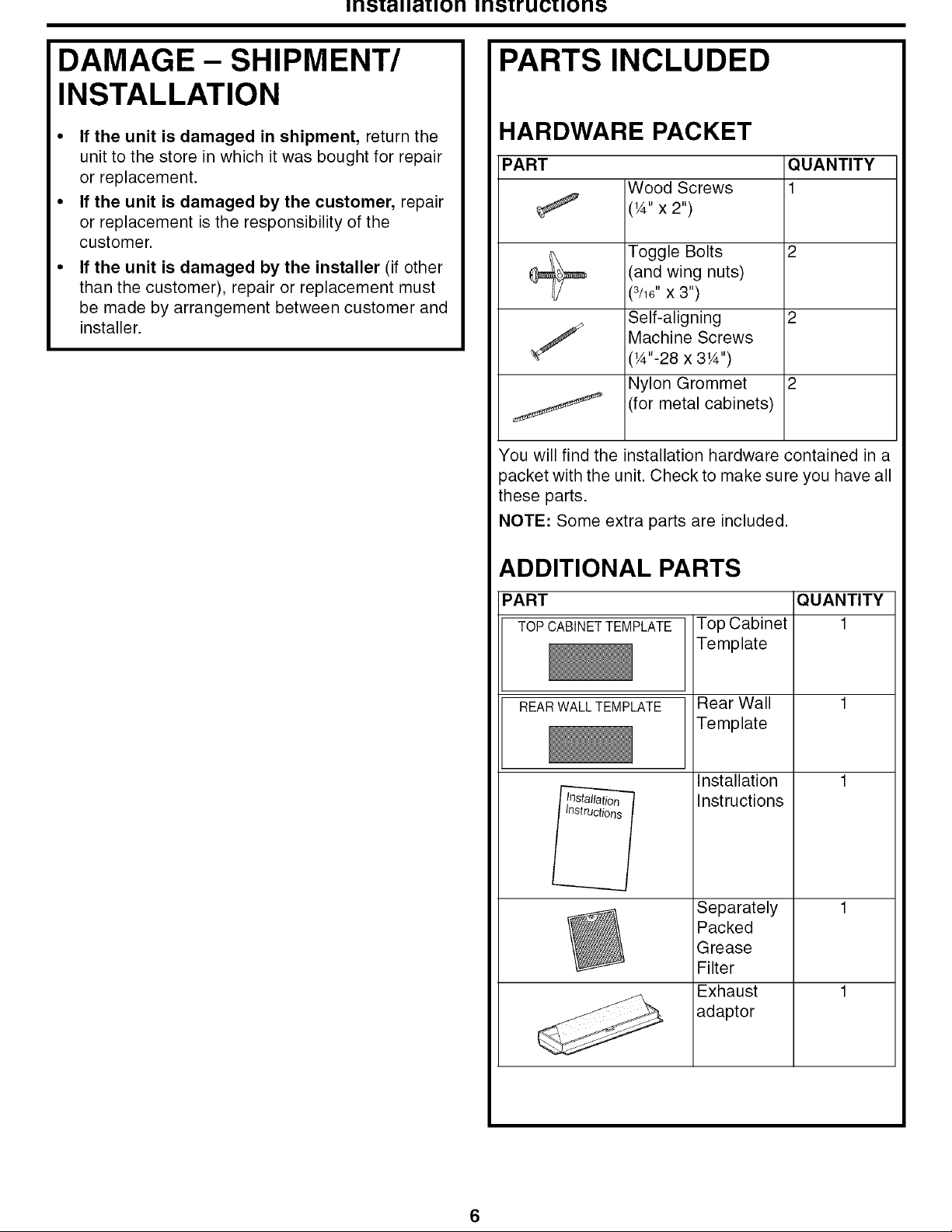
DAMAGE- SHIPMENT/
INSTALLATION
• If the unit is damaged in shipment, return the
unit to the store in which it was bought for repair
or replacement.
• If the unit is damaged by the customer, repair
or replacement is the responsibility of the
customer.
• If the unit is damaged by the installer (if other
than the customer), repair or replacement must
be made by arrangement between customer and
installer.
PARTS INCLUDED
HARDWARE PACKET
PART QUANTITY
Wood Screws 1
(W'x 2")
Toggle Bolts 2
(and wing nuts)
(3/16"x 3")
Self-aligning 2
Machine Screws
('A"-28 x 3'A")
Nylon Grommet 2
(for metal cabinets)
You will find the installation hardware contained in a
3acket with the unit. Check to make sure you have all
these parts.
NOTE: Some extra parts are included.
ADDITIONAL PARTS
PART
TOP CABINET TEMPLATE
REAR WALL TEMPLATE
Top Cabinet
Template
Rear Wall
Template
Installation
Instructions
Separately
Packed
Grease
Filter
Exhaust
adaptor
QUANTITY
1
irlS[alla[iorl irlstrucuorl_5
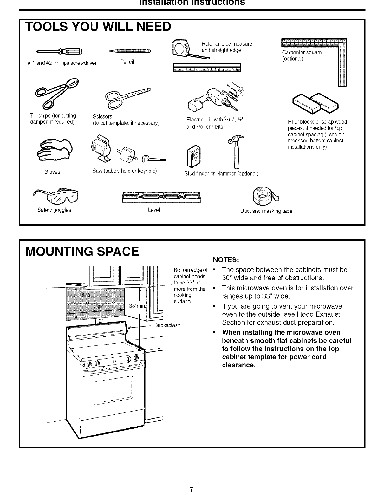
TOOLS YOU WILL NEED
# 1 and #2 Phillips screwdriver Pencil
Ruler or tape measure
straight edge
Carpentersquare
(optional)
Tin snips (for cutting
damper, if required)
Gloves
Safetygoggles
Scissors
(to cut template, if necessary)
Saw (saber, hole or keyhole)
MOUNTING SPACE
Level
Backsplash
Electric drillwith 3/16", 1/2"
and S/s"drill bits
Studfinder or Hammer (optional)
NOTES:
Bottomedge of "
cabinet needs
to be 33" or
more from the "
cooking
surface
The space between the cabinets must be
30" wide and free of obstructions.
This microwave oven is for installation over
ranges up to 33" wide.
Q
If you are going to vent your microwave
oven to the outside, see Hood Exhaust
Section for exhaust duct preparation.
When installing the microwave oven
beneath smooth flat cabinets be careful
to follow the instructions on the top
cabinet template for power cord
clearance.
Fillerblocks or scrap wood
pieces, if needed for top
cabinet spacing (used on
recessed bottomcabinet
installations only)
Duct and masking tape
irlS[alla[iorl irlstrucuorl_5
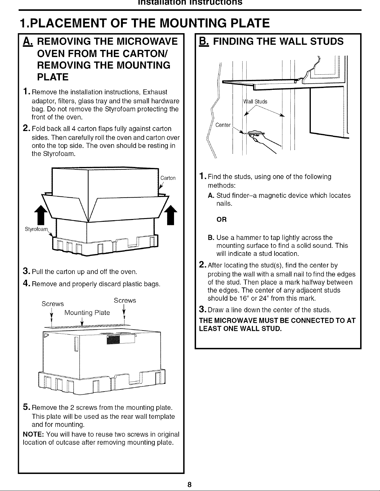
1.PLACEMENT OF THE MOUNTING PLATE
A. REMOVING THE MICROWAVE
OVEN FROM THE CARTON/
REMOVING THE MOUNTING
PLATE
1, Remove the installation instructions, Exhaust
adaptor, filters, glass tray and the small hardware
bag. Do not remove the Styrofoam protecting the
front of the oven.
2. Fold back all 4 carton flaps fully against carton
sides. Then carefully roll the oven and carton over
onto the top side. The oven should be resting in
the Styrofoam.
B. FINDING THE WALL STUDS
,j
L -
i II
i ,
Center
1. Find the studs, using one of the following
methods:
A. Stud finder-a magnetic device which locates
nails.
OR
H
3. Pull the carton up and off the oven.
4. Remove and properly discard plastic bags.
Screws
Mounting Plate _
5, Remove the 2 screws from the mounting plate.
This plate will be used as the rear wall template
and for mounting.
NOTE: You will have to reuse two screws in original
location of outcase after removing mounting plate.
Screws
!
B. Use a hammer to tap lightly across the
mounting surface to find a solid sound. This
will indicate a stud location.
2. After locating the stud(s), find the center by
probing the wall with a small nail to find the edges
of the stud. Then place a mark halfway between
the edges. The center of any adjacent studs
should be 16" or 24" from this mark.
3. Draw a line down the center of the studs.
THE MICROWAVE MUST BE CONNECTED TO AT
LEAST ONE WALL STUD.
 Loading...