

Tappan TGF657BFB9, TGF605WFW9, TGF605WFW6, TGF605WFW8, TGF657BFW9 Installation Guide
...
INSTALLATION AND SERVICE MUST BE PERFORMED BY
A QUAUHED INSTALLER.
IMPORTANT: SAVE FOR LOCAL ELECTRICAL INSPECTOR'S USE.
READ AND SAVE THESE INSTRUCTIONS FOR FUTURE REFERENCE,
If the information in this manua[ is not fommowed exactmy, a fire or expmosion may resumt [
causing property damage, personal injury or death.
FOR YOUR SAFETY:
-- Do not store or use gasoline or other flammable vapors and liquids in the vicinity of this or any other
J WHAT TO DO IF YOU SMELL GAS:
Do not try to mightany appmiance.
® Do not touch any electrical switch; do not use any phone in your buiMing.
mmmediatemy call your gas supplier from a neighbor's phone. Follow the gas suppmier's instructions.
® ff you cannot reach your gas suppmier,cammthe fire department.
i Installation and service must be performed by a quamified installer, sewice agency or the gas suppmier.
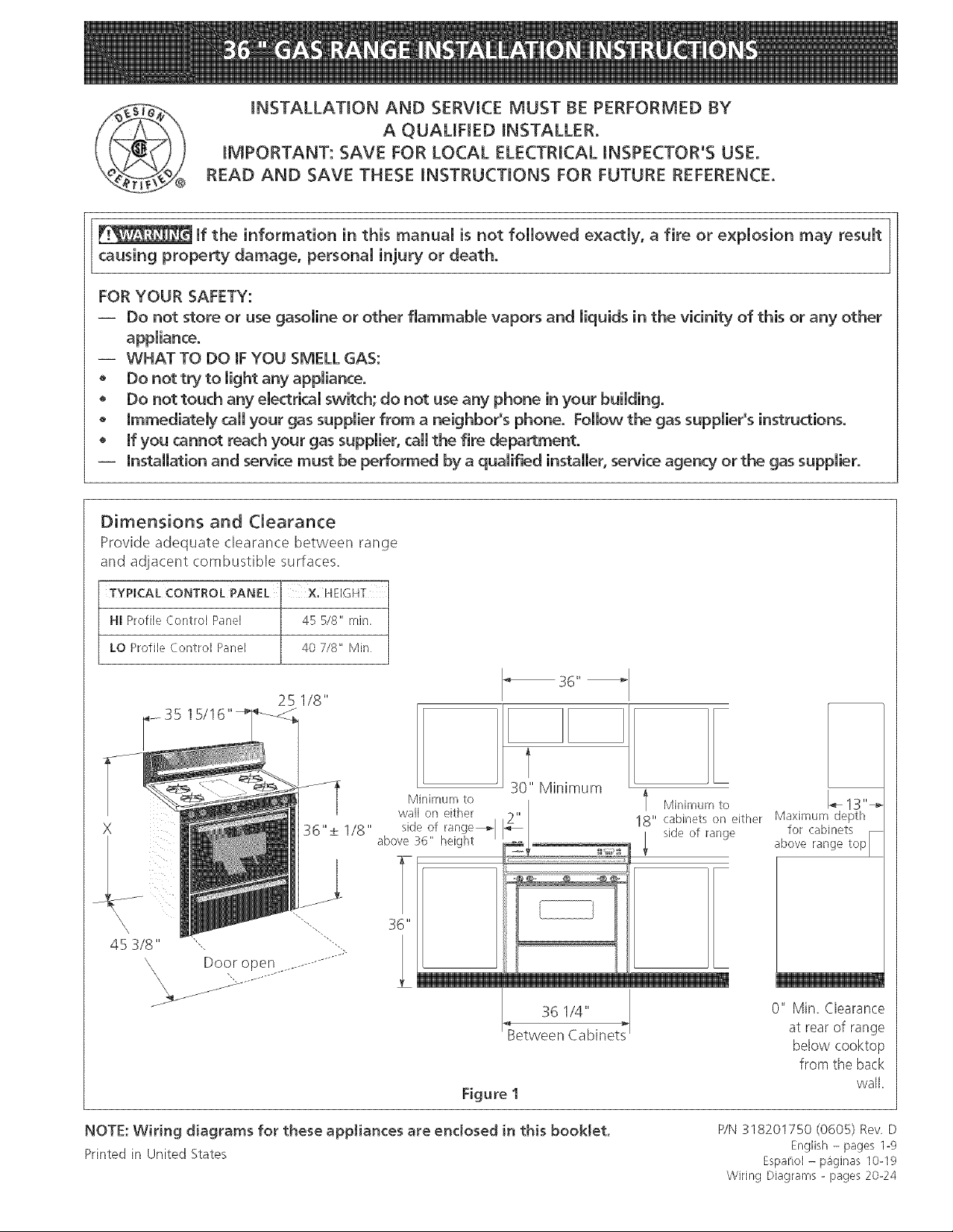
Dimensions and Clearance
Provide adequate clearance between range
and adjacent combustible surfaces.
q
TYPICAL CONTROL PANEL
HI Profile Control Panel 45 5/8" mJn,
LO Profile Control Panel 40 7/8" Min
25 118"
35
x
45 3/8"
\\
\
Door open ..........
j_
Minimum to
wall on either
36"
30" Minimum
_Between Cabinets
Figure I
36 114"
l Minimum to 1_13"--_
18" cabinets on either Maximum depth
side of range
0" Min, Clearance
at rear of range
below cooktop
from the back
wall,
NOTE: Wiring diagrams for these appliances are enclosed in this booklet,
Printed in United States
P/N 318201750 (0605) Rev, D
English - pages 1-9
Espaflol - p_ginas 10-19
Wiring Diagrams - pages 20-24
Important Notes to the Installer
1. Readall instructions contained in these installation
instructions before installing the range.
2. Remove all packing material before connecting the
electrical supply to the appliance.
3. Observe all governing codes and ordinances.
4. Besure to leave these instructions with the consumer.
Important Note to the Consumer
Keep these instructions with your Useand Care Guide for
future reference.
IMPORTANT SAFETY
INSTRU S
Installation of this range must conform with local codes,
or in the absence of local codes, with the National Fuel
Gas Code ANSI Z223. l--latest edition.
This range has been design certified by American Gas
Association (A.G.A.). As with any appliance using gas
and generating heat, there are certain safety precautions
you should follow. You will find them in the Use and
Care Guide read it carefully.
• Be sure your range is installed and grounded
properly by a qualified installer or service
technician.
• This range must be electrically grounded in
accordance with local codes, or in their absence,
with the National Electrical Code ANSI/NFPA No.
70--Jatest edition.
• Tile installation of appliances designed for
manufactures (mobile) home installation must conform
with Manufactured Home Construction and Safety
Standard, title 24CFR, part 3280 [Formerly tile Federal
Standard for Mobile Home Construction and Safety,
title 24, HUD (part 280)] or when such standard is not
applicable, the Standard for Manufactured Home
Installation 1982 (Manufactured Home Sites,
Communities and Set ups), ANS! Z225.1 latest edition,
or local codes.
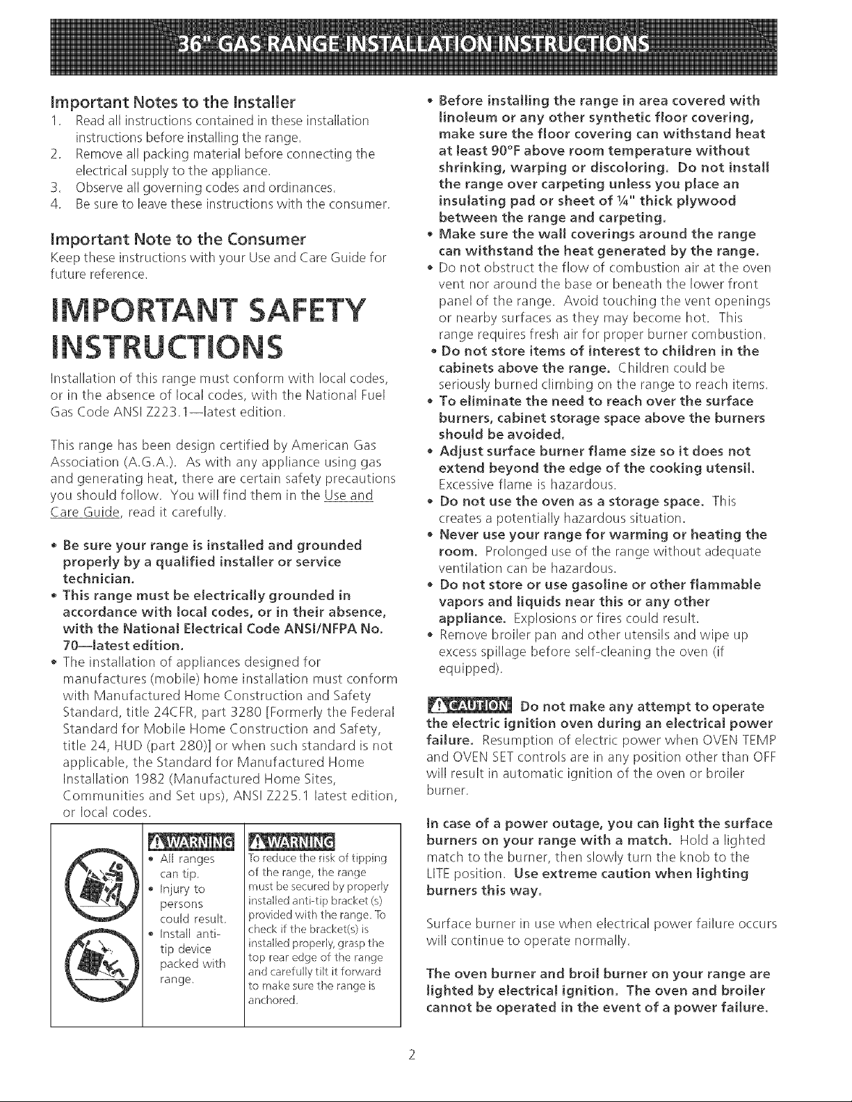
All ranges
can tip
• Injuryto
persons
could result.
Install anti-
tip device
packed with
range.
lb reduce the risk of tipping
of the range, the range
must be secured by properly
installed anti-tip bracket (s)
installed properly, grasp the
top rear edge ol tile range
and carefully tilt it forward
to make sure tile range is
anchored
• Before installing the range in area covered with
linoleum or any other synthetic floor covering,
make sure the floor covering can withstand heat
at least 9B°F above room temperature without
shrinking, warping or discoloring. Do not instatt
the range over carpeting unless you place an
insulating pad or sheet of 1/4"thick ptywood
between the range and carpeting.
• Make sure the wall coverings around the range
can withstand the heat generated by the range.
• Do not obstruct the flow of combustion air at the oven
vent nor around the base or beneath the lower front
panel of the range. Avoid touching the vent openings
or nearby surfaces as they may be(ome hot. This
range requires fresh air for proper burner combustion.
• Do not store items of interest to children in the
cabinets above the range. Children could be
seriously burned climbing on the range to reach items.
• To eliminate the need to reach over the surface
burners, cabinet storage space above the burners
should be avoided.
• Adjust surface burner flame size so it does not
extend beyond the edge of the cooking utensil.
Excessive flame is hazardous.
• Do not use the oven as a storage space. This
creates a potentially hazardous situation.
• Never use your range for warming or heating the
room. Prolonged use of the range without adequate
ventilation (an be hazardous.
• Do not store or use gasoline or other flammable
vapors and tiquids near this or any other
appliance. Explosions or fires could result.
• Remove broiler pan and other utensils and wipe up
excess spillage before self-cleaning the oven (if
equipped).
Do not make any attempt to operate
the electric ignition oven during an electrical power
failure. Resumption of electric power when OVEN TEMP
and OVEN SETcontrols are in any position other than OFF
will result in automatic ignition of the oven or broiler
burner.
tn case of a power outage, you can light the surface
burners on your range with a match. Hold a lighted
match to the burner, then slowly turn the knob to the
LITEposition. Use extreme caution when tighting
burners this way.
Surface burner in use when electrical power failure occurs
will continue to operate normally.
The oven burner and broil burner on your range are
tighted by eJectrical ignition. The oven and broiter
cannot be operated in the event of a power failure.

1, Before Installing the Range
Remove shipping material
Remove all tape, shipping and packaging materials and
the oven rack packaging. Lift up cooktop and remove
the two shipping screws from the cooktop burners (see
figure 2). Screws
/d
i
B. Install Y2" flare union adaptor supplied with the
connector, to the Y2" NPT internal thread on pressure
regulator.
Gas Connection for Electric Ignition Models
FlareUnion Adaptor
Figure 2
2. Provide an Adequate Gas SuppNy
This range is designed to operate on natural gas at 4" of
manifold pressure or on LPgas at !0" of manifold
pressure. It is shipped from the factory set for natural
gas. If it isto be used with LPgas, adjustments must be
made.
A convertible pressure regulator is connected in series
with tile manifold of the range and must remain in series
with the supply line regardless of whether natural or LP
gas is being used.
For proper operation, the maximum inlet pressure to
the regulator must be no more than 14" of water column
(W.C.) pressure.
For checking the regulator, the inlet pressure must be at
least 1" water column pressure greater than the
regulator manifold outlet setting. If tile regulator is set
for 4" of manifold pressure, the inlet pressure must be at
least5". If the regulator isset for l0", the inlet pressure
must be at least 11 ".
Flexible Appliance
Connector
C. Because solid pipe restricts moving the range we
recommended use of A.G.A. design certified flexible
metal appliance connector. Connect flexible
appliance to flare union.
D. Move range into approximate position and connect
flexible appliance connector to gas supply line with
proper flare union adaptor. The adaptor supplied with
the flexible connector must be used.
E. Check for leaks. Turn the gas supply on tile range
and use a liquid leak detector at all joints and
connections to check for leaks in tile system.
3-Wire Polarized
120V.Outlet
32 7Is" -+Y4' Supply
Pressure
Regulator
Figure 3
Pipe
The gas supply line into the range should be Y2" or %"
I.D. flexible metal appliance connector five feet in
length.
3. Seal the Openings
Seal any openings in tile wall behind the range and in
the floor under tile range when hookups are completed.
4. Connect the Range to Gas
Refer to figure 4 to 7 for recommended connections.
A. tnstall a manual shut-off valve in the gas line in an
easily accessible location outside of the range. Be
sure you know how and where to shut-off tile gas
supply to tile range.
20" 6%"
or Lower l
'
..'" 361/4"
Recommended locations for installing the electrical
outlet and pipe opening may be adjusted to meet
specific requirements.
Figure 4
Donotuseaflameto checkforleaks
fromgasconnections,Checkingforleakswithaflame
mayresultinafireorexplosion.
Disconnectthisrangeandits individualshutoff
valvefromthegassupplypipingsystemduringany
pressuretestingofthatsystemattestpressuresgreater
than14"ofwatercolumnpressure(approx.Y2" psig).
Isolate the range from the gas supply piping system
by (:losing its individual manual shutoff valve during any
pressure testing of tile gas supply piping system at test
pressures equal to or lessthan 14" of water column
(approx. Y2" psig).
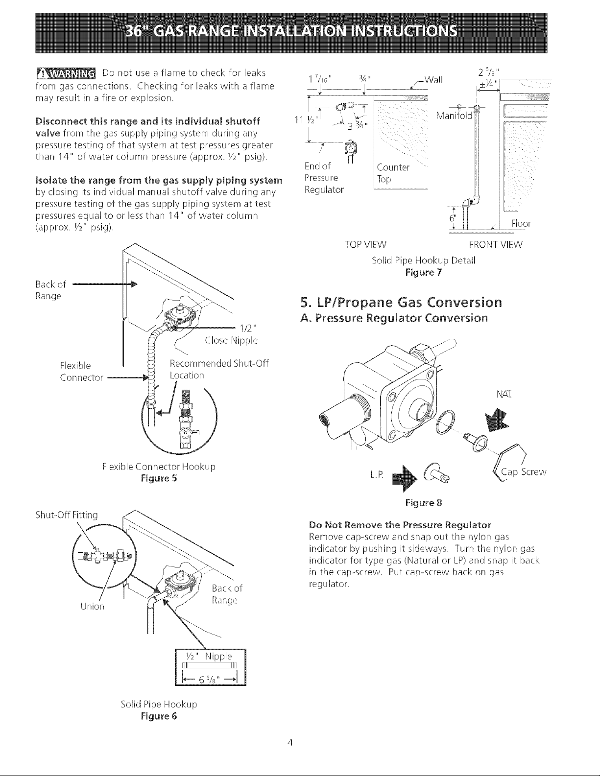
Back of
Range
1/2"
Close Nipple
17/16" 3A"
/ Wall
¸¸¸¸¸¸i!¸¸ii!¸_¸¸ii¸¸!¸i_¸¸¸¸¸¸¸¸¸¸¸i¸!¸_¸!¸!i¸¸i¸i¸i¸!I
Counter
Top
Regulator
TOPVIEW FRONTVIEW
Solid Pipe Hookup Detail
Figure 7
5. LP/Propane Gas Conversion
A. Pressure Regulator Conversion
2 5/8 "
T
O
iii ii_
i I
Floor
/
Flexible
Connector
Shut-Off Fitting
Union
Recommended Shut-Off
jocation
Flexible Connector Hookup
Figure 5
Back of
Range
NAT.
L.R _ (_ Cap Screw
Figure 8
Do Not Remove the Pressure Regulator
Remove cap-screw and snap out tile nylon gas
indicator by pushing it sideways. Turn the nylon gas
indicator for type gas (Natural or LP)and snap it back
in tile cap-screw. Put cap-screw back on gas
regulator.
Solid Pipe Hookup
Figure 6
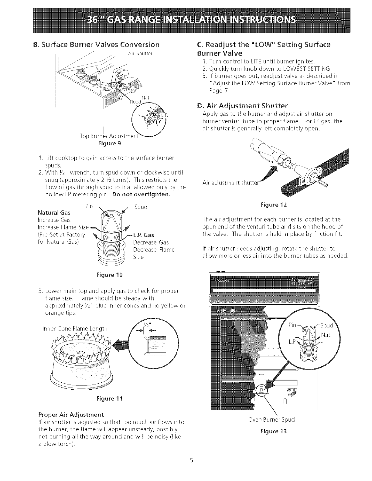
B. Surface Burner Valves Conversion
Air Shutter
Nat.
Top Burne J
1. Lift cooktop to gain access to the surface burner
spuds.
2. With V2" wrench, turn spud down or clockwise until
snug (approximately 2 V2turns). This restricts the
flow of gas through spud to that allowed only by the
hollow LP metering pin. Do not overtighten.
[[rAd
Figure 9
C. Readjust the "LOW" Setting Surface
Burner Valve
1. Turn control to LITEuntil burner ignites.
2. Quickly turn knob down to LOWEST SETTING.
3. If burner goes out, readjust valve as described in
"Adjust the LOW Setting Surface Burner Valve" from
Page 7.
D. Air Adjustment Shutter
Apply gas to the burner and adjust air shutter on
burner venturi tube to proper flame. ForLPgas, the
air shutter is generally left completely open.
Air adjustment shutter_
Pin
Natural Gas X
Spud
Increase Gas
Increase Flame Size-_,_
(Pre-Set at Factory
for Natural Gas)
.4
/_L.R Gas
Decrease Gas
Decrease Flame
Size
Figure 10
3. Lower main top and apply gas to check for proper
flame size. Flame should be steady with
approximately Y2" blue inner cones and no yellow or
orange tips.
Figure 12
The air adjustment for each burner is located at tile
open end of the venturi tube and sits on the hood of
the valve. The shutter is held in place by friction fit.
If air shutter needs adjusting, rotate the shutter to
allow more or less air into the burner tubes as needed.
Figure 11
Proper Air Adjustment
If air shutter is adjusted so that too much air flows into
the burner, the flame will appear unsteady, possibly
not burning all the way around and will be noisy (like
a blow torch).
Oven Burner Spud
Figure 13
E. Convert Oven Burner Orifice
1. Remove storage drawer if equipped or lower panel
to gain access to oven burner spuds.
2. Remove oven bottom and oven burner baffle
located on top of burner. To remove oven bottom,
pull up at rear, disengaged front of bottom from
oven front frame, and pull the oven bottom straight
out of tile oven. Remove burner baffle so that the
burner flame (:an be observed.
3. Using V2" wrench, turn down the adjustable spud
which injects gas into the oven burner, until snug
against the LP metering pin. This will be
approximately 2 Y2turns. Do Not Overtighten.
4. Push tile BAKE TEMP button, then SETthe
temperature to 300°F. Wait until burner starts to
cycle. To determine if the oven burner flame is
proper, observe the flame. It should be steady with
approximately 1" blue cones and no _ellow or
orange flame tips.
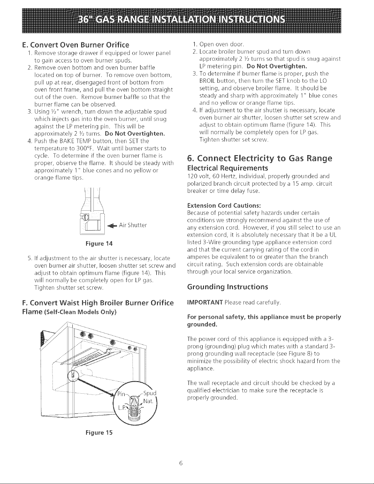
f _ Air Shutter
Figure 14
5. If adjustment to the air shutter is necessary, locate
oven burner air shutter, loosen shutter set screw and
adjust to obtain optimum flame (figure 14). This
will normally' be completely' open for LP gas.
Tighten shutter set screw.
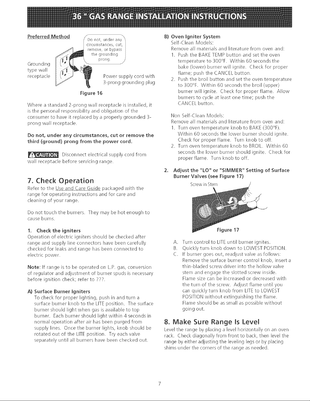
1. Open oven door.
2. Locate broiler burner spud and turn down
approximately 2 V2turns so that spud is snug against
LPmetering pin. Do NotOvertighten.
3. To determine if burner flame is proper, push the
BROILbutton, then turn the SETknob to the LO
setting, and observe broiler flame. It should be
steady and sharp with approximately 1" blue (.ones
and no yellow or orange flame tips.
4. If adjustment to the air shutter is necessary, locate
oven burner air shutter, loosen shutter set screw and
adjust to obtain optimum flame (figure 14). This
will normally be completely open for LPgas.
Tighten shutter set screw.
5. Connect Electricity to Gas Range
Electrical Requirements
120 volt, 60 Hertz, individual, properly grounded and
polarized branch circuit protected by a 15 amp. circuit
breaker or time delay fuse.
Extension Cord Cautions:
Because of potential safety hazards under certain
conditions we strongly recommend against the use of
any extension cord. However, if you still select to use an
extension cord, it is absolutely necessary that it be a UL
listed 3-Wire grounding type appliance extension cord
and that the current carrying rating of the cord in
amperes be equivalent to or greater than the branch
circuit rating. Such extension cords are obtainable
through your local service organization.
Grounding Instructions
F. Convert Waist High Broiler Burner Orifice
Flame (Self-Clean Models Only)
Figure 15
IMPORTANT Please read carefully.
For personal safety, this appliance must be properly
grounded.
The power cord of this appliance is equipped with a B-
prong (grounding) plug which mates with astandard 3-
prong grounding wall receptacle (see Figure 8) to
minimize the possibility of electric shock hazard from tile
appliance.
The wall receptacle and circuit should be checked by a
qualified electrician to make sure tile receptacle is
properly grounded.
Preferred Method
Do not, under any
circumstances, cut,
remove, or bypass
the grounding
prong,
Grounding
type wall
receptacle
Power supply cord with
3-prong grounding plug
Figure 16
Where a standard 2-prong wall receptacle is installed, it
isthe personal responsibility and obligation of the
consumer to have it replaced by a properly grounded 3-
prong wall receptacle.
Do not, under any circumstances, cut or remove the
third (ground} prong from the power cord.
Disconnect electrical supply cord from
wall receptacle before servicing range.
7. Check Operation
Refer to the Use and Care Guide packaged with the
range for operating instructions and for care and
cleaning of your range.
B) Oven Igniter System
Self-Clean Models:
Remove all materials and literature from oven and:
1. Push the BAKE TEMP button and set the oven
temperature to 300°F. Within 60 seconds the
bake (lower) burner will ignite. Check for proper
flame; push the CANCEL button.
2. Push the broil button and set the oven temperature
to 300°F. Within 60 seconds the broil (upper)
burner will ignite. Check for proper flame. Allow
burners to cycle at least one time; push tile
CANCEL button.
Non Self-Clean Models:
Remove all materials and literature from oven and:
1. Turn oven temperature knob to BAKE(300°F).
Within 60 seconds the lower burner should ignite.
Check for proper flame. Turn knob to off.
2. Turn oven temperature knob to BROIL. Within 60
seconds the lower burner should ignite. Check for
proper flame. Turn knob to off.
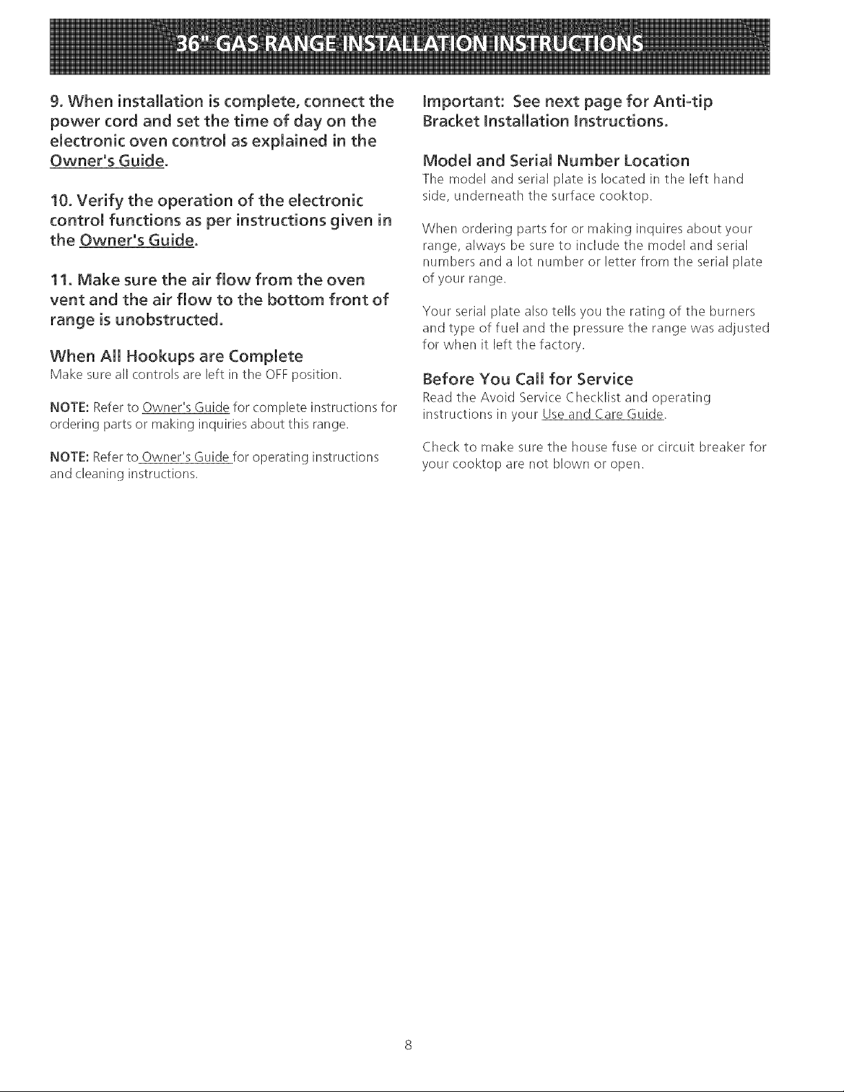
2. Adjust the "LO" or "SIMMER" Setting of Surface
Burner Valves (see Figure 17)
Screwin Stem
Do not touch tile burners. They may be hot enough to
cause burns.
1. Check the igniters
Operation of electric igniters should be checked after
range and supply line connectors have been (arefull\
checked for leaks and range has been connected to
electric power.
Note: If range is to be operated on LP. gas, conversion
of regulator and adjustment of burner spuds is necessary
before ignition check; refer to ???.
A} Surface Burner Igniters
To check for proper lighting, push in and turn a
surface burner knob to the LITEposition. The surface
burner should light when gas is available to top
burner. Each burner should light within 4 seconds in
normal operation after air has been purged from
supply lines. Once the burner lights, knob should be
rotated out of theLITE position. Try each valve
separately until all burners have been checked out.
Figure 17
A.
Turn control to LITEuntil burner ignites.
B.
Quickly turn knob down to LOWESTPOSITION.
C.
If burner goes out, readjust valve asfollows:
Remove the surface burner control knob, insert a
thin-bladed screw driver into the hollow valve
stem and engage tile slotted screw inside.
Flame size can be increased or decreased with
the turn of the screw. Adjust flame until you
can quickly turn knob from LITEto LOWEST
POSITIONwithout extinguishing tile flame.
Flame should be as small as possible without
going out.
8. Make Sure Range Is Level
Level the range by placing a level horizontally on an oven
rack. Check diagonally from front to back, then level the
range by either adjusting the leveling legs or by placing
shims under the corners of the range as needed.
9. When installation is complete, connect the
power cord and set the time of day on the
electronic oven control as explained in the
Owner's Guide.
10. Verify the operation of the electronic
control functions as per instructions given in
the Owner's Guide,
11. Make sure the air flow from the oven
vent and the air flow to the bottom front of
range is unobstructed,
When All Hookups are Complete
Make sure all controls are left in the OFFposition.
NOTE: Refer to Owner's Guide for complete instructions for
ordering parts or making inquiries about this range.
NOTE: Refer to Owner's Guide for operating instructions
and cleaning instructions.
important: See next page for Antiotip
Bracket installation instructions.
Model and Serial Number Location
Tile model and serial plate is located in tile left hand
side, underneath tile surface cooktop.
When ordering parts for or making inquires about your
range, always be sure to include the model and serial
numbers and a lot number or letter frora the serial plate
of your range.
Your serial plate also tells you the rating of the burners
and type of fuel and the pressure the range was adjusted
for when it left the factory.
Before You Call for Service
Read the Avoid Service Checklist and operating
instructions in your Use and Care Guide.
Check to make sure the house fuse or circuit breaker for
your cooktop are not blown or open.
 Loading...