

Page 1
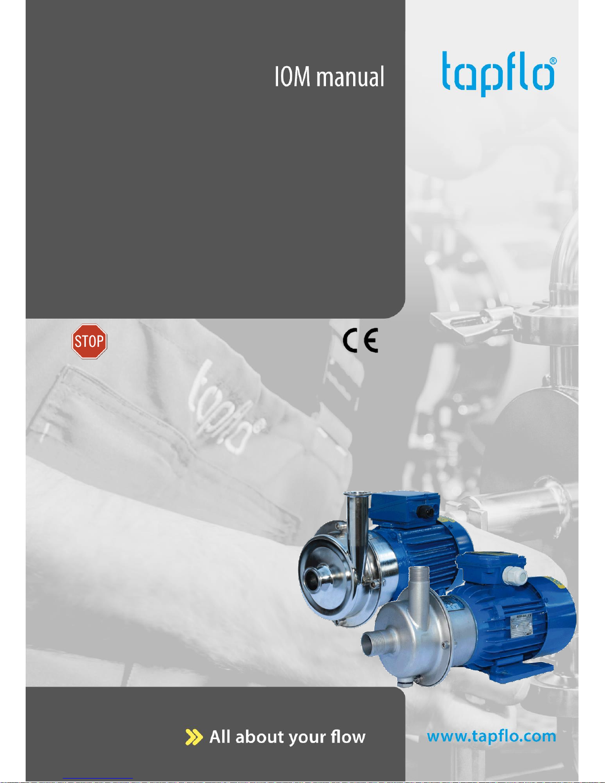
CTI
CTH
CTI
CTH
With 2900 rpm motor:
With 2900 rpm motor:
With 1450 rpm motor:
With 1450 rpm motor:
CTI AA-03
CTH AA-03
CTI AA-024
CTH AA-024
CTI AA-05
CTH AA-05
CTI BB-054
CTH BB-054
CTI BB-07
CTH BB-07
CTI CC-114
CTH CC-114
CTI CC-15
CTH CC-15
CTI CE-114
CTH CE-114
CTI CC-22
CTH CC-22
CTI DD-224
CTH DD-224
CTI CE-15
CTH CE-15
CTI DF-224
CTH DF-224
CTI CE-22
CTH CE-22
CTI DG-224
CTH DG-224
CTI DD-40
CTH DD-40
CTI DF-40
CTH DF-40
CTI DG-40
CTH DG-40
CTI DF-60
CTH DF-60
CTI DG-60
CTH DG-60
CTI EF-55
CTH EF-55
CTI EG-55
CTH EG-55
CTI EF-75
CTH EF-75
CTI EG-75
CTH EG-75
CTI EG-110B
CTH EG-110B
CTI & CTH
Centrifugal Pumps
edition 2018 rev 2
Original instruction
Read this instruction manual carefully,
before you install and operate the pump.
Page 2

CONTENTS
IOM manual CTI & CTH centrifugal pumps 2
0. GENERAL ..................................................................................................................................... 6
0.1. Introduction................................................................................................................................ 6
0.2. Warning symbols ....................................................................................................................... 6
0.3. Qualification and training of personnel ................................................................................... 6
1. INSTALLATION ................................................................................................................................... 7
1.1. Operation principle .................................................................................................................... 7
1.2. Receiving inspection .................................................................................................................. 7
1.3. Storage ........................................................................................................................................ 7
1.4. Foundation ................................................................................................................................. 7
1.5. Environment ............................................................................................................................... 8
1.6. Suction and discharge piping ................................................................................................... 8
1.6.1. Connection of discharge pipe ........................................................................................... 8
1.6.2. Connection of suction pipe ............................................................................................... 8
1.7. Health and safety ....................................................................................................................... 9
1.7.1. Protection ........................................................................................................................... 9
1.7.2. Electrical safety .................................................................................................................. 9
1.7.3. Chemical hazard ................................................................................................................. 9
1.7.4. Dry running ........................................................................................................................ 9
1.7.5. Noise level .......................................................................................................................... 9
1.7.6. Temperature hazards ......................................................................................................... 9
1.7.7. Rotating parts................................................................................................................... 10
1.7.8. Cleaning and disinfection ................................................................................................ 10
1.8. Example of installation ............................................................................................................ 10
1.9. Instruments............................................................................................................................... 11
1.9.1. Electric power ................................................................................................................... 11
1.9.2. Optional instruments ....................................................................................................... 11
1.9.3. Thermometer .................................................................................................................... 11
1.10. Motor connection .................................................................................................................... 11
1.11. Motor standard ........................................................................................................................ 12
2. OPERATION ...................................................................................................................................... 13
2.1. Start-up ..................................................................................................................................... 13
2.1.1. Starting the pump ............................................................................................................ 13
2.1.2. Restarting after power shut-off ...................................................................................... 13
2.2. Stopping the pump .................................................................................................................. 14
2.3. Cleaning and disinfection ........................................................................................................ 14
Page 3

CONTENTS
IOM manual CTI & CTH centrifugal pumps 3
2.3.1. Cleaning procedure .......................................................................................................... 14
2.4. Residual risks ............................................................................................................................ 15
2.5. Disposal after expiration of the expected lifetime ............................................................... 15
2.6. Waste of electrical and electronic equipment (WEEE) directive .......................................... 15
2.7. Actions in emergency .............................................................................................................. 15
3. MAINTENANCE ................................................................................................................................ 16
3.1. Inspections ................................................................................................................................ 16
3.2. Location of faults ..................................................................................................................... 16
3.3. Disassembly of the pump ........................................................................................................ 17
3.3.1. Disassembly procedure .................................................................................................... 17
3.4. Assembly of the pump ............................................................................................................. 19
3.4.1. Test run ............................................................................................................................. 23
3.5. Disassembly – 4FZ option ........................................................................................................ 23
3.6. Assembly – 4FZ option ............................................................................................................ 26
3.6.1. Test run ............................................................................................................................. 26
4. OPTIONS ................................................................................................................................... 27
4.1. Lubricated seal – 4Z ................................................................................................................. 27
4.2. Flushed seal – 4F (API Plan 11) ............................................................................................... 29
4.3. Heating / cooling jacket – 4J................................................................................................... 30
4.4. Hygienic shroud – M ................................................................................................................ 30
4.5. Pump drain – 4K ....................................................................................................................... 31
4.6. Long coupled execution – B .................................................................................................... 31
4.7. Semi-open impeller – 4H; Reinforced impeller – 4W ............................................................ 32
4.8. Reinforced pump casing – 4B ................................................................................................. 33
4.9. Increased number of mounting holes – 4O ........................................................................... 33
4.10. External quench – 4Q ............................................................................................................... 34
4.11. Mechanical seal options .......................................................................................................... 34
5. SPARE PARTS .................................................................................................................................... 35
5.1. Spare parts drawing ................................................................................................................. 35
5.2. Spare parts list .......................................................................................................................... 35
5.3. Spare parts drawing - options ................................................................................................ 36
5.4. Spare parts list - options ......................................................................................................... 37
5.5. Spare parts – long coupled execution .................................................................................... 38
5.6. Spare parts list – long coupled execution .............................................................................. 38
5.7. Recommended spare parts ...................................................................................................... 39
5.8. How to order parts................................................................................................................... 39
Page 4

CONTENTS
IOM manual CTI & CTH centrifugal pumps 4
6. DATA ................................................................................................................................................. 40
6.1. Pump code ................................................................................................................................ 40
6.2. Dimensions - CTI ...................................................................................................................... 41
6.3. Dimensions - CTH..................................................................................................................... 42
6.4. Dimensions – CTI long coupled pump ................................................................................... 43
6.5. Materials, data and limits ........................................................................................................ 44
6.6. Mounting torques and dimensions of screws/nuts .............................................................. 44
6.7. Performance curves ................................................................................................................. 45
6.8. Permitted loads on inlet and outlet ....................................................................................... 46
7. WARRANTY ...................................................................................................................................... 47
7.1. Returning parts ........................................................................................................................ 47
7.2. Warranty ................................................................................................................................... 47
7.3. Warranty form .......................................................................................................................... 49
Page 5

www.tapflo.com
EC DECLARATION OF CONFORMITY 01/EC/CT/2016
Series:
CTI / CTH …
Serial numbers:
2016 - … (from 1604 - …)
Manufactured by:
Tapflo AB
Filaregatan 4
442 34 Kungälv, Sweden
This declaration of conformity is issued under the sole responsibility of the manufacturer.
Object of declaration: SINGLE STAGE VERTICAL CENTRIFUGAL PUMPS
The object of the declaration described above is in conformity with the relevant Union
harmonization legislation:
Directive 2006/42/EC of European Parliament and of the Council of 17 May 2006 on machinery,
amending Directive 95/16/EC;
Directive 2014/35/UE of the European Parliament and of the Council of 14 February 2014 on
harmonization of the laws of Member States relating to electrical equipment designed for use
within certain voltage limits;
Mr Michał Śmigiel is authorized to compile the technical file.
Tapflo Sp. z o.o.
ul. Czatkowska 4b
83-110 Tczew
Signed for and on behalf of Tapflo AB:
Håkan Ekstrand
Managing director
Tapflo AB, 16.04.2016
Page 6
0. GENERAL
IOM manual CTI & CTH centrifugal pumps 6
0. GENERAL
0.1. Introduction
The CT pumps are open or semi open single stage centrifugal pumps. They are
manufactured in high finish and mechanical strong material stainless steel AISI 316L. The
pump range meets the demands from a variety of today’s industries.
The industrial series CTI is designed with glass blasted pump casing. A variety of connection
types, mechanical seal options and other executions are available to satisfy most type of
industrial duties.
The hygienic series CTH is supplied with electro polished pump casing and internals. This
series is specially dedicated for hygienic duties in food, beverage and pharmaceutical
industries, where clean- and drain-ability are important factors.
With proper attention to maintenance, CT pumps will give efficient and trouble free
operation. This instruction manual will familiarise operators with detailed information about
installing, operating and maintaining the pump.
0.2. Warning symbols
The following warning symbols are present in this instruction manual. This is what they say:
This symbol stands next to all safety instructions in this instruction manual
where danger to life and limb may occur. Observe these instructions and
proceed with utmost caution in these situations. Inform also other users of all
safety instructions. In addition to the instructions in this instruction manual, the
general safety and accident prevention regulations must be observed.
This signal stands at points in this instruction manual of particular importance
for compliance with regulations and directives, for correct work flow and for the
prevention of damage to and destruction of the pump.
This symbol signals possible danger caused by the presence of electric fields or
live wires.
0.3. Qualification and training of personnel
The personnel in charge of installation, operation and maintenance of the pumps we
produce must be qualified to carry out the operations described in this manual. Tapflo shall
not be held responsible for the training level of personnel and for the fact that they are not
fully aware of the contents of this manual.
Page 7
1. INSTALLATION
IOM manual CTI & CTH centrifugal pumps 7
1. INSTALLATION
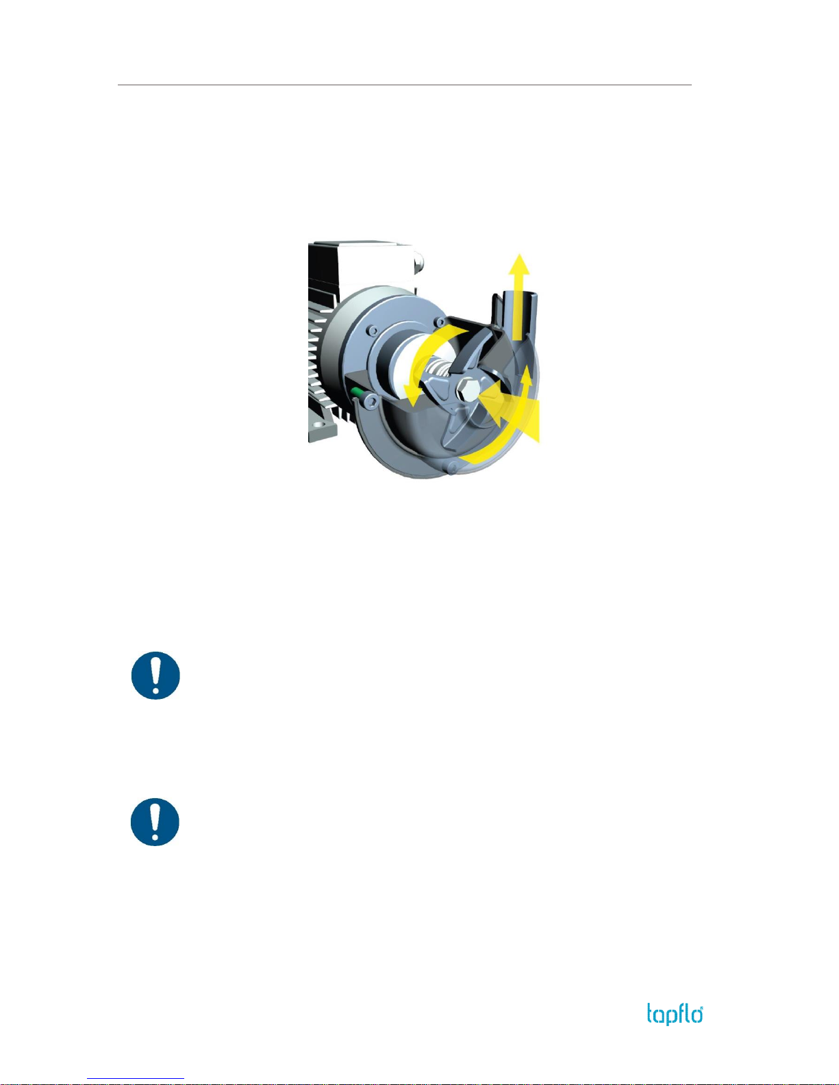
1.1. Operation principle
In order to operate the pump, the casing has to be filled with liquid before start-up. The
liquid enters the pump casing axially to the shaft. The rotating impeller generates a
centrifugal force accelerating the liquid through the pump casing and into the discharge
piping.
1.2. Receiving inspection
Although precaution is taken by us when packing and shipping, we urge you to carefully
check the shipment on receipt. Make sure that all parts and accessories listed on the packing
list are accounted for. Immediately report any damage or shortage to the transport company
and to us.
1.3. Storage
If the equipment is to be stored prior to installation, place it in a clean location. Do not
remove the protective covers from the suction and discharge which have been fastened to
keep pump internals free of debris. Clean the pump thoroughly before installation.
When in storage, turn the shaft by hand at least twice per week. The pump-motor unit should
always be stored indoor in dry, vibration and dust free conditions.
1.4. Foundation
The pump-motor unit must stand on and be fixed to a sufficiently rigid structure that can
support the entire perimeter on which the unit stands. The foundation on a firm bottom is
the most satisfactory. Once the pump is in position, adjust level with metal shims between
the feet and the surface on which it stands. Check that the feet of the pump motor unit stand
well on each of them. The surface on which the foundation stands must be flat and
horizontal. If the unit is fitted on a steel structure, make sure that it is supported so that the
feet do not warp. In any case, it is advisable to fit some anti-vibration rubber pieces between
the pump and the brickwork. The motor needs an additional stand as its level is higher than
that of the pump casing. As an option the pump can be ordered with feet for the motor. For
close-coupled type, pump motor alignment is not required.
Page 8

1. INSTALLATION
IOM manual CTI & CTH centrifugal pumps 8
1.5. Environment
There should be enough space in the vicinity of the pump in order to operate, maintain
and repair it.
The area in which the pump is operated, must be sufficiently ventilated. Excessive
temperature, humidity or dirt may affect the pump operation.
Behind the cooling fan of the motor there must be sufficient room for the hot air to
escape the motor.
1.6. Suction and discharge piping
A pump is generally part of a piping system that can include a number of components such
as valves, fittings, filters, expansion joints, instruments, etc. The way the piping is arranged
and the positioning of the components has a great influence on the operation and the
lifetime of the pump. The pump cannot be used as a support for the components connected
to it.
The flow of liquid from the pump must be as even as possible. It is advisable to avoid any
tight bends or drastic reductions of diameters that may cause flow resistance in the
installation. In case of diameter reduction, it is advisable to use appropriate conical
reductions (possibly eccentric on suction side and concentric on discharge side) at changes
of diameter and at a minimum distance from pump connections of five diameters.
1.6.1. Connection of discharge pipe
A check-valve and a shut-off/regulation valve are normally fitted on the discharge side.
The check-valve protects the pump from any backflow. The shut-off/regulation valve cuts off
the pump from the line and adjusts the output. Never adjust flow rate using the valve on the
suction pipe.
1.6.2. Connection of suction pipe
The suction piping is very important for the correct operation of the pump assembly. It must
be as short and as direct as possible. If a longer suction line is unavoidable, the diameter
should be large enough, i.e. at least as the inlet connection on the pump, to ensure less flow
resistance. In any case, suction must be carried out properly avoiding any air locks.
The CT pumps are single-stage centrifugal pumps, thus not self-priming. It will therefore
always be necessary to install a bottom valve in all cases when the static height of the liquid
is lower than the suction height of the pump. It is also crucial that the whole suction line is
filled with liquid prior to starting the pump. The suction piping must be air tight. Critical
points in these terms are also the seals between flanges and the seals of the valve stems.
Even some small air let into the suction line cause serious operating problems that can make
the pump stop. It is recommended to use check-valve in the suction line to avoid siphoning
when the pump stops.
Page 9
1. INSTALLATION
IOM manual CTI & CTH centrifugal pumps 9
1.7. Health and safety
The pump must be installed according to local and national safety rules.
The pumps are constructed for particular applications. Do not use the pump on
applications different from that for which it was sold without consulting us to ascertain
its suitability.
1.7.1. Protection
In the interest of health and safety it is essential to wear protective clothing and safety
goggles when operating, and/or working in the vicinity of Tapflo pumps.
1.7.2. Electrical safety
Do not carry out any maintenance or/and operation on the pump while it is running or before
it has been disconnected from the power supply. Avoid any danger caused by electric power
(for details see current regulations in force). Check that electrical specifications on the data
plate are equivalent to the power supply to which it will be connected.
1.7.3. Chemical hazard
Whenever the pump is to be used for pumping a different liquid, it is essential to clean the
pump beforehand in order to avoid any possible reaction between the two products.
1.7.4. Dry running
Do not start nor carry out running tests before filling the pump with liquid. Always avoid dry
operation of the pump. Start the pump when it is completely filled and with the valve on the
discharge side almost completely closed.
1.7.5. Noise level
CT pumps, including the motor, in normal operating conditions produce a sound level below
80 dB(A). The major sources of noise are: liquid turbulence in the installation, cavitation or
any other abnormal operation that is independent from the pump construction nor the
pump manufacturer. The user must provide suitable protective means if the sources of noise
could produce a harmful noise level for operators and for the environment (in compliance
with current local regulations).
1.7.6. Temperature hazards
Raised temperature can cause damage on the pump and/or piping and may also be
hazardous for personnel in the vicinity of the pump/piping. The hot or cold parts of the
machine must be protected to avoid accidental contacts
Page 10
1. INSTALLATION
IOM manual CTI & CTH centrifugal pumps 10
1.7.7. Rotating parts
Do not tamper with the protection of the rotating parts, do not touch or approach rotating
parts in movement.
1.7.8. Cleaning and disinfection
Cleaning and disinfection of the pump system is of greatest importance when the pump is
used in a food process installation. Use of a pump system that is NOT cleaned or disinfected
can cause contamination of the product.
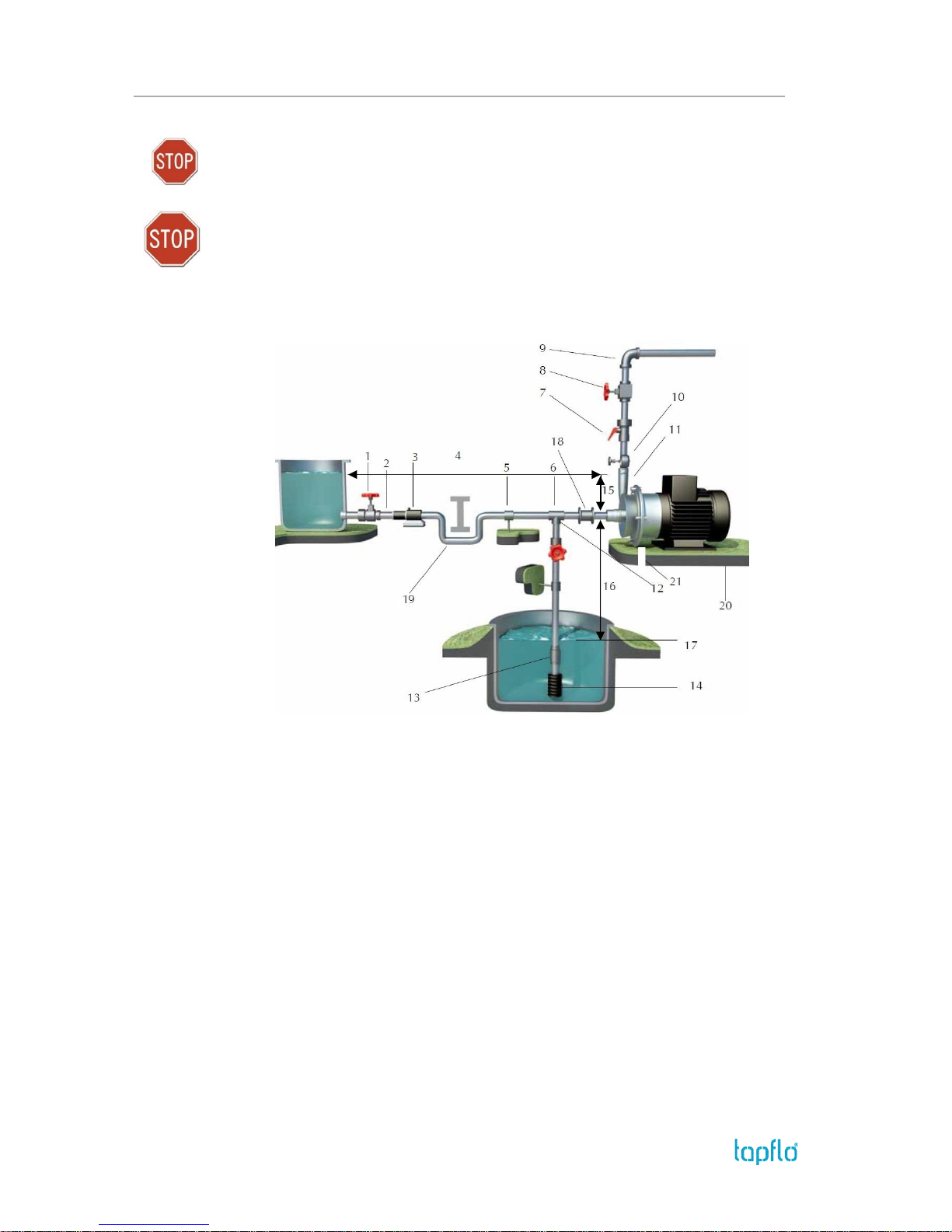
1.8. Example of installation
1) YES: Gate valve (may also be near pump in case of long piping)
2) With positive head: tilt of piping towards pump
3) YES: line strainer if particles are present
4) NO: air pockets – the circuit must be short and straight
5) YES: pipe fastening
6) Suction line as short and direct as possible
7) YES: attachment for gauge or safety pressure switch
8) YES: adjusting gate valve on outlet
9) Bends placed after valves and instruments not closer to the pump inlet than five times the piping diameter
10) YES: attachment for gauge or safety pressure switch
11) NO: elbow joints (and other parts) on the pump (discharge and suction lines)
12) With negative suction lift: tilt of piping towards suction tank
13) YES: check valve (with negative suction lift)
14) YES: strainer if particles are present
15) Suction head varies according to flow in order to prevent windage
16) Suction head
17) Immersion depth
18) YES: expansion joint (indispensable with long pipes or hot liquids) and/or anti-vibration facility during
discharge and suction; anchored near to pump
19) YES: overcoming obstacles at lower depths
20) Fix the pump by the fixing holes provided: the supports must be level
21) YES: drainage channel around base
Page 11
1. INSTALLATION
IOM manual CTI & CTH centrifugal pumps 11
1.9. Instruments
In order to ensure a proper control of the performance and the conditions of the installed
pump, we recommend using the following instruments:
- a pressure-vacuum gauge on the suction piping;
- a pressure gauge on the discharge piping.
The pressure intakes must be made of straight pieces of piping at a distance of minimum
five diameters from the pump inlets. The pressure gauge on discharge must always be fitted
between the pump and the shut-off / regulation valve. The output can be read on the
pressure gauge, transformed into meters and then compared with the typical curves.
1.9.1. Electric power
The electric power absorbed by the motor can be measured by means of a wattmeter or an
amp gauge.
1.9.2. Optional instruments
The optional instruments can indicate if pump is working in an abnormal way. The abnormal
conditions can be caused by: accidentally closed valves, lack of pumped liquid, overloads,
etc.
1.9.3. Thermometer
If the temperature of the pumped liquid is a critical parameter, provide the installation with
a thermometer (preferably on the suction side).
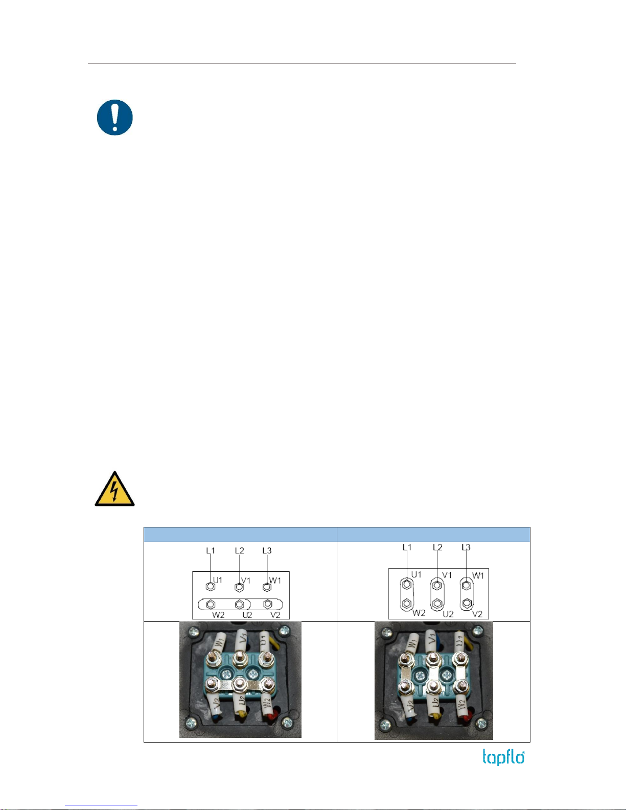
1.10. Motor connection
An expert electrician must always carry out the electrical connection. Compare the power
supply with the data plate specifications and then choose a suitable connection. The type of
connection is stated on the motor data plate and can be Y (star) or D (Delta), according to
the power supply of the motor (see figure below).
STAR
DELTA
Page 12

1. INSTALLATION
IOM manual CTI & CTH centrifugal pumps 12
Follow the connection standard used in the plant. In no case connect the electrical motor
directly to supply network but use a suitable electric switchboard equipped with a knife
switch and suitable safety devices (e.g. motor breaker switches) in the power circuit. Safety
devices against overloads must also protect the motors. Make sure that the motor has
suitable grounding and that it has been connected properly.
1.11. Motor standard
As a standard Tapflo CT pump are equipped with motors of the following parameters:
International Mounting Arrangement – B34
Number of poles / Rotation speed [rpm] – 2
Non ATEX
Protection grade – IP55
Voltage – 3 phase
Motor power
RPM
Voltage
Frequency
0,37 kW
2900
Δ230 / Υ400
50 Hz
3500
Δ265 / Υ460
60 Hz
0,55 kW
2900
Δ230 / Υ400
50 Hz
3500
Δ265 / Υ460
60 Hz
0,75 kW
2900
Δ230 / Υ400
50 Hz
3500
Υ460
60 Hz
1,5 kW
2900
Δ230 / Υ400
50 Hz
3500
Δ265 / Υ460
60 Hz
2,2 kW
2900
Δ230 / Υ400
50 Hz
3500
Δ265 / Υ460
60 Hz
4,0 kW
2900
Δ400 / Υ690
50 Hz
3500
Δ460
60 Hz
5,5 kW
2900
Δ400 / Υ690
50 Hz
3500
Δ460
60 Hz
6,0 kW
2900
Δ400 / Υ690
50 Hz
7,5 kW
2900
Δ400 / Υ690
50 Hz
11 kW
2900
Δ400 / Υ690
50 Hz
Page 13
2. OPERATION
IOM manual CTI & CTH centrifugal pumps 13
2. OPERATION
2.1. Start-up
Check manually that the motor is free to turn, moving the motor cooling fan.
Make sure that the piping is not clogged and is free from residues or foreign objects.
Make sure that the liquid flows regularly into the pump.
The pump and piping connected to it, at least the suction pipe, must be full of liquid.
Any air or gas must be carefully released. In case of suction with negative head, fill the
suction piping and check how the bottom valve works. It must guarantee that the liquid
must not flow back, emptying therefore the suction pipe with consequent disconnection
of the pump.
The suction shut-off valve (if any) must be completely open.
The shut-off / regulation valve on the discharge side must be completely closed.
The motor must turn in the same direction as the arrow shown on the pump. The
direction of rotation is always clockwise looking at the pump from the motor side; check
by starting briefly, then looking at the direction of rotation of the motor fan through the
fan lid. If it is wrong, the motor must be stopped immediately. Change the connection
to the terminals of the electric motor (chapter 1.10 “Motor connection”) and repeat the
procedure described above.
Any auxiliary connections must all be connected.
If the pump is equipped with an oil reservoir, make sure to fill it before start-up.
2.1.1. Starting the pump
Start the electric motor and open the discharge shut-off / regulation valve gradually until the
desired output has been reached. The pump must not run two or three minutes with closed
discharge. Longer operation in these conditions can seriously damage the pump.
If the pressure shown on the pressure gauge on the discharge piping does not increase, turn
off the pump immediately and release pressure carefully. Repeat the connection procedure.
If there are changes of flow rate, head, density, temperature or viscosity of the liquid, stop
the pump and get in touch with our technical service.
2.1.2. Restarting after power shut-off
In case of accidental stopping, make sure that the non-return valve has prevented backflow
and check that the motor cooling fan has stopped. Start the pump again following the
instructions of chapter 2.1.1 ”Starting the pump”.
If the pump intakes from a lower level than it is positioned, it can un-prime during the
standstill and therefore you must check again before starting that the pump and the suction
piping are full of liquid.
Page 14
2. OPERATION
IOM manual CTI & CTH centrifugal pumps 14
2.2. Stopping the pump
It is advisable to close the discharge shut-off / regulation valve gradually and stop the motor
immediately after. The reverse sequence is not recommendable, especially with larger pumps
or longer delivery piping. That is to avoid any problems due to water hammering. If a suction
shutoff valve has been installed, it is advisable to close it completely after pump is fully
stopped.
2.3. Cleaning and disinfection
Cleaning and disinfection of the pump system is of greatest importance when the pump is
used in a food processing installation. Use of a pump system that is NOT cleaned or
disinfected can cause contamination of the product. The cleaning cycles as well as chemicals
to use for the cleaning vary depending on the pumped product and the process. The user is
responsible to establish a suitable cleaning and / or disinfection program according to local
and public health and safety regulations.
2.3.1. Cleaning procedure
The pump may be cleaned in two different ways:
CIP (Cleaning In Place)
without dismantling the pump, using steam, water or cleaning chemicals. Follow these safety
instructions during the CIP procedure:
Make sure that all cleaning line connections are properly tightened to avoid splashing
of hot water or cleaning chemicals.
When using an automatic process, a safety device should be installed to avoid
unintentional automatic start-up of the pump.
Before any disassembly of the pump, fittings or pipes, make sure that the cleaning cycle
is finished.
Manual cleaning
by simply dismantling the pump casing, impeller and mechanical seal. Always follow these
safety instructions:
Switch off the electric power to the motor and disconnect the motor starting system if
installed.
The cleaning personnel shall wear suitable protective clothing, footwear and goggles.
Use a suitable non-toxic and non-flammable cleaning solution.
Always keep the area around the pump clean and dry.
Never clean the pump by hand with pump running.
Page 15

2. OPERATION
IOM manual CTI & CTH centrifugal pumps 15
2.4. Residual risks
Even with proper application and observance of all points listed in this operating manual,
there is still an estimable and unexpected residual risk when using the pumps. It may leak,
fail due to wear, application-related causes or system-related circumstances.
2.5. Disposal after expiration of the expected lifetime
The metallic components like aluminium, stainless steel and carbon steel can be recycled.
Plastic parts are not recyclable and must be disposed of as residual waste. The pump must
be disposed of properly, according to local regulations. It should be noted that potentially
dangerous fluid residues may remain in the pump and can create a hazard to the operator
or the environment, therefore the pump has to thoroughly cleaned before disposal.
2.6. Waste of electrical and electronic equipment (WEEE) directive
Users of electrical and electronic equipment (EEE) with the WEEE
marking per Annex IV of the WEEE Directive must not dispose of end of
life EEE as unsorted municipal waste, but use the collection framework
available to them for the return, recycle, recovery of WEEE and minimize
any potential effects of EEE on the environment and human health due
to the presence of hazardous substances. The WEEE marking applies
only to countries within the European Union (EU) and Norway. Appliances are labelled in
accordance with European Directive 2002/96/EC. Contact your local waste recovery agency
for a designated collection facility in your area.
2.7. Actions in emergency
In case of a leakage of an unknown fluid, respiratory protection should be worn and contact
with the fluid avoided. During firefighting, no special hazards are to be expected from the
pump itself. In addition, the currently handled fluid and the corresponding safety data sheet
must be taken into account.
In the event of personal injury, the appropriate emergency number or 112 must be chosen.
Page 16
3. MAINTENANCE
IOM manual CTI & CTH centrifugal pumps 16
3. MAINTENANCE
Maintenance work on electrical installations must be performed by qualified
personnel and only when the power supply has been shutoff. Follow the local
and national safety regulations.
3.1. Inspections
Periodically check suction and discharge pressures.
Inspect the motor according to the instructions from the motor manufacturer.
In general, a mechanical seal does not require maintenance, but the pump should never
run when empty (dry). If a leakage occurs, replace the mechanical seal.
3.2. Location of faults
Overheating of motor Insufficient flow rate or pressure in pump No pressure on the discharge side
Irregular discharge flow / pressure Noise and vibrations The pump gets
clogged
Overheating of the pump Abnormal wear Leak in mechanical seal
Possible reason
Solution
X X
Wrong direction of rotation
Invert the direction of rotation
X X X X
Insufficient suction head (NPSH)
Increase available NPSH:
X
Pump is clogged
Clean the pump
X X X X
Cavitation
Increase suction pressure
X X X X
The pump sucks air
Make sure all connections are tight
X X X
Suction pipe is blocked
Check pipes / valves and filters on the suction line
X X
Discharge pressure too high
Reduce the head by increasing pipe diameter and/or
reduce number of valves and bends
X X X
Flow rate too high
Reduce the flow:
X X X X X
Liquid temperature too high
Cool the liquid
X
Broken or worn mechanical seal
Replace the seal
X
Wrong material of O-rings for the liquid
Mount O-rings in other material (contact us)
X X X X
The impeller scratches
Reduce the temperature and / or suction pressure.
Adjust clearance between housing and impeller
X X
Loads on the pipes
Connect the pipes independent of the pump
X X X X
Foreign objects in the liquid
Use a filter on the suction side
X
Spring tension too low on mechanical seal
Adjust as mentioned in this manual
X
Shut-off valve closed on suction side
Check and open the valve
X
Discharge pressure too low
Increase the pressure – install an impeller with a bigger
diameter (contact us)
X X
Pump is not filled with liquid
Fill pump with liquid
X X X
Liquid parameters different than calculated
Check pumped liquid parameters
Page 17
3. MAINTENANCE
IOM manual CTI & CTH centrifugal pumps 17
3.3. Disassembly of the pump
The disassembly should be performed only by qualified personnel.
Each operation to be fulfilled with the machine must always be carried out once all the
electrical contacts have been disconnected. The pump-motor unit must be placed in a
position where it cannot be started unintentionally.
Before servicing in any way the parts that come in contact with the pumped liquid, make
sure that the pump has been fully emptied and washed. When draining the liquid, make
sure that there is no danger for people or the environment.
The numbers put in brackets, refer to the part numbers in the spare part drawings and spare
part lists in chapter 4 “Spare parts”.
3.3.1. Disassembly procedure
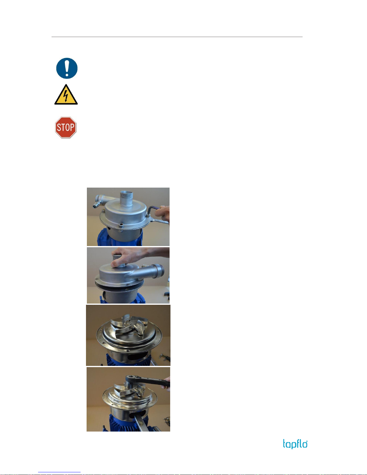
Fig. 3.3.1
Unscrew the casing mounting screws [141] and
remove them with the nuts [143] and washers [142].
Fig. 3.3.2
Take off the pump casing [13].
Fig. 3.3.3
Remove the O-ring [18].
NOTE! After every disassembly the O-ring [18] has
to be replaced by a new one.
Fig. 3.3.4
Remove the impeller mounting screw [191] and the
washer [192], use a spanner key in the opening of the
pump back cover [11] to hold the shaft [16] during
assembly and disassembly of the impeller. Remove
the impeller.
Page 18
3. MAINTENANCE
IOM manual CTI & CTH centrifugal pumps 18
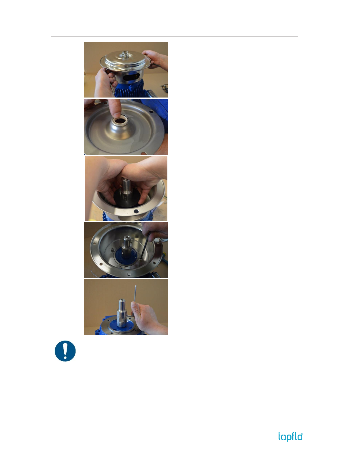
Fig 3.3.5
Carefully remove the back casing [12]. The static part
[15B] of the mechanical seal will remain in the back
casing.
Fig 3.3.6
If necessary, push out the static part [15B] of the
mechanical seal.
NOTE! Apply some alcohol or water before pushing
out of the mechanical seal.
Fig 3.3.7
Remove the deflector [17].
Fig 3.3.8
Remove the screws [121] and washers [122]
fastening the back cover [11] to the motor [10].
Fig 3.3.9
Loosen the lock screws [161] and remove the shaft
extension [16].
The pump is now completely disassembled. Check all components, especially the mechanical
seal, for wear or damage and replace if necessary. The casing O-ring should be replaced
after every pump disassembly!
Page 19
3. MAINTENANCE
IOM manual CTI & CTH centrifugal pumps 19
3.4. Assembly of the pump
The assembly procedure is done in the reverse order to the disassembly.
Nevertheless there are a few things that you have to remember in order to assemble the
pump correctly.
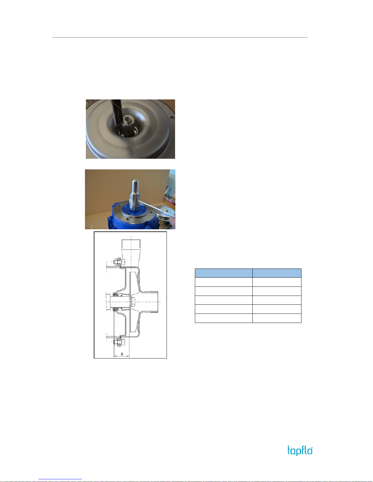
Fig. 3.4.1
Before inserting the static part [15B] of the
mechanical seal, fit the back casing [12] onto the
back cover [11] and check the seal fitting dimension
according to the table below. This ensures that
correct pressure is applied on the mechanical seal by
the impeller.
NOTE! This is a very important procedure when you
have taken off the shaft extension.
Fig. 3.4.2
Using a calliper, adjust the “S” dimension.
It is achievable by loosening the lock screws [161]
and moving the shaft extension [16] up or down.
Pump type
S [mm]
CT A
33
CT B
33
CT C
35.5
CT D
35.5
CT E
35.5
Page 20
3. MAINTENANCE
IOM manual CTI & CTH centrifugal pumps 20
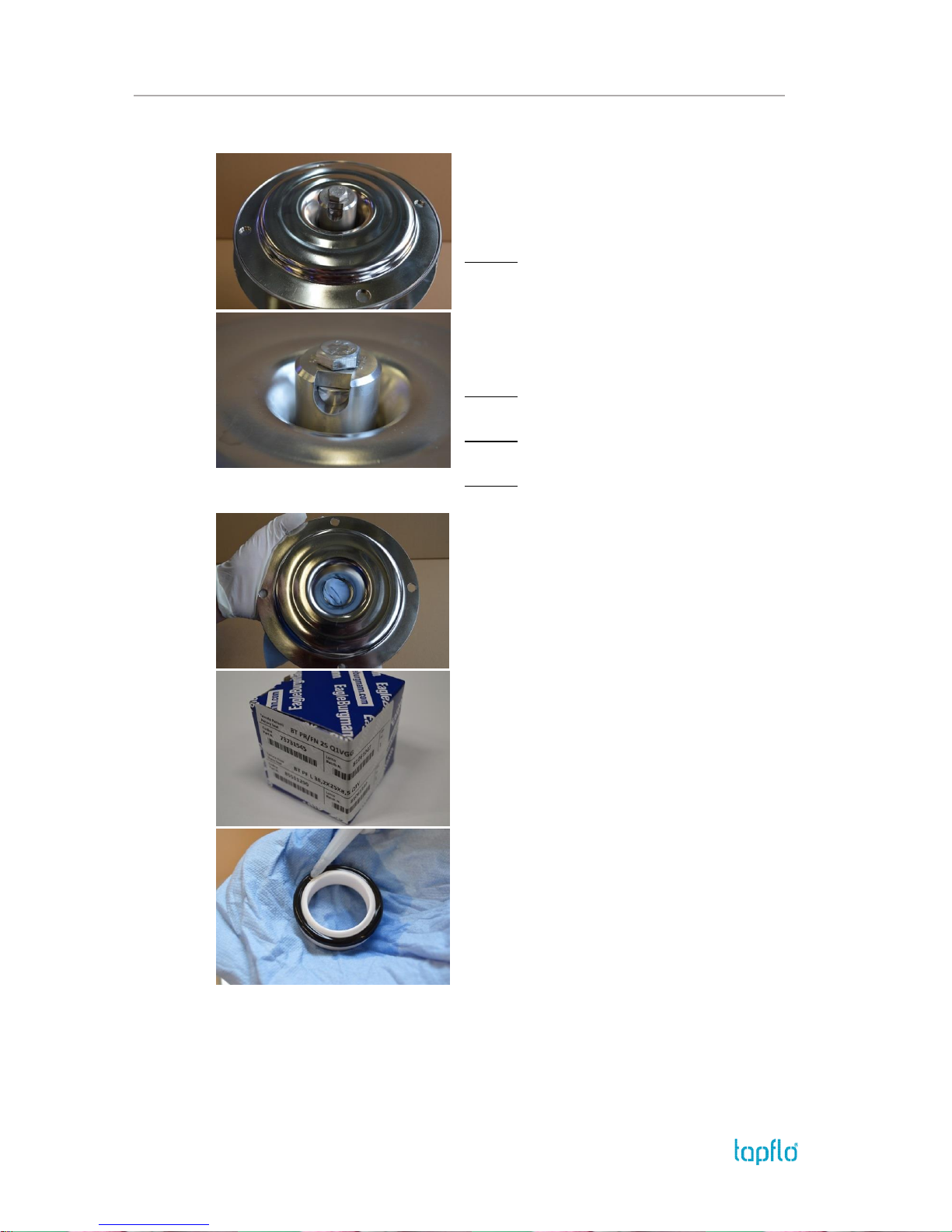
Fig. 3.4.3 – alternative way of assembly
„S” dimension can also be set by special Tapflo tool
[T]. Put the tool [T] onto the shaft extension [16] and
fix it with the screw [191], then lean the tool [T]
against internal rim of the back casing [12]. Using an
allen key fix the shaft [16] by tightening screws [161].
NOTE1! Pay attention to the application of the tool
[T]. There are 3 types of tools matching the following
pump sizes:
CT A, CT B
CT C, CT D, CT E
CT C, CT D, CT E with reinforced shaft
NOTE2! The inspection hole allows you to check
whether the face of the shaft [16] touches the tool.
NOTE3! After tightening screw [161] remember to
take off the mounting tool [T].
NOTE4! The set of special tools can be purchased
under Tapflo code 5-355-16MTS
Fig. 3.4.4
Precisely clean and degrease with alcohol the
internal rim of back casing [12]. Check if the rim
surface is smooth. If not it may be cause of
mechanical seal leakage.
NOTE! For cleaning use dust-free material e.g. blue
towel TORK 1230081.
Fig. 3.4.5
While unpacking pay attention to the application
(industrial / hygienic) of the mechanical seal [15].
Fig. 3.4.6
Lubricate the static part [15B] of mechanical seal to
provide more accurate assembly as well as prevent
the O-ring from blocking before reaching the surface
of the internal rim.
Page 21
3. MAINTENANCE
IOM manual CTI & CTH centrifugal pumps 21
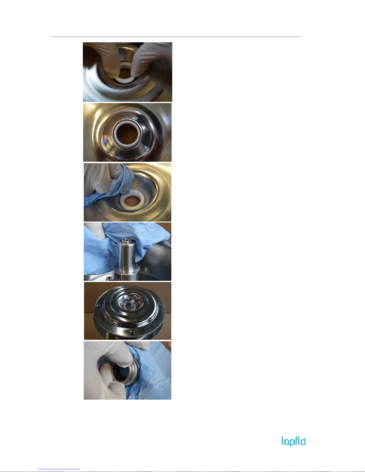
Fig. 3.4.7
Simultaneously with both hands push the static part
[15B] of mechanical seal until the end.
Fig. 3.4.8
Ensure that the static par of mechanical seal is evenly
spaced around the circumference.
NOTE! Check if O-ring does not springs back. It may
springs back when O-ring does not reach the surface
of the internal rim.
Fig. 3.4.9
Once again degrease surface of the recess and the
sliding face of the static part of mechanical seal.
Fig. 3.4.10
Clean and degrease the shaft extension [16].
Fig. 3.4.11
Fit the back casing [12] onto the back cover [11].
Fig. 3.4.12
Precisely clean and degrease the sealing face of the
dynamic part of the mechanical seal [15A].
Page 22
3. MAINTENANCE
IOM manual CTI & CTH centrifugal pumps 22
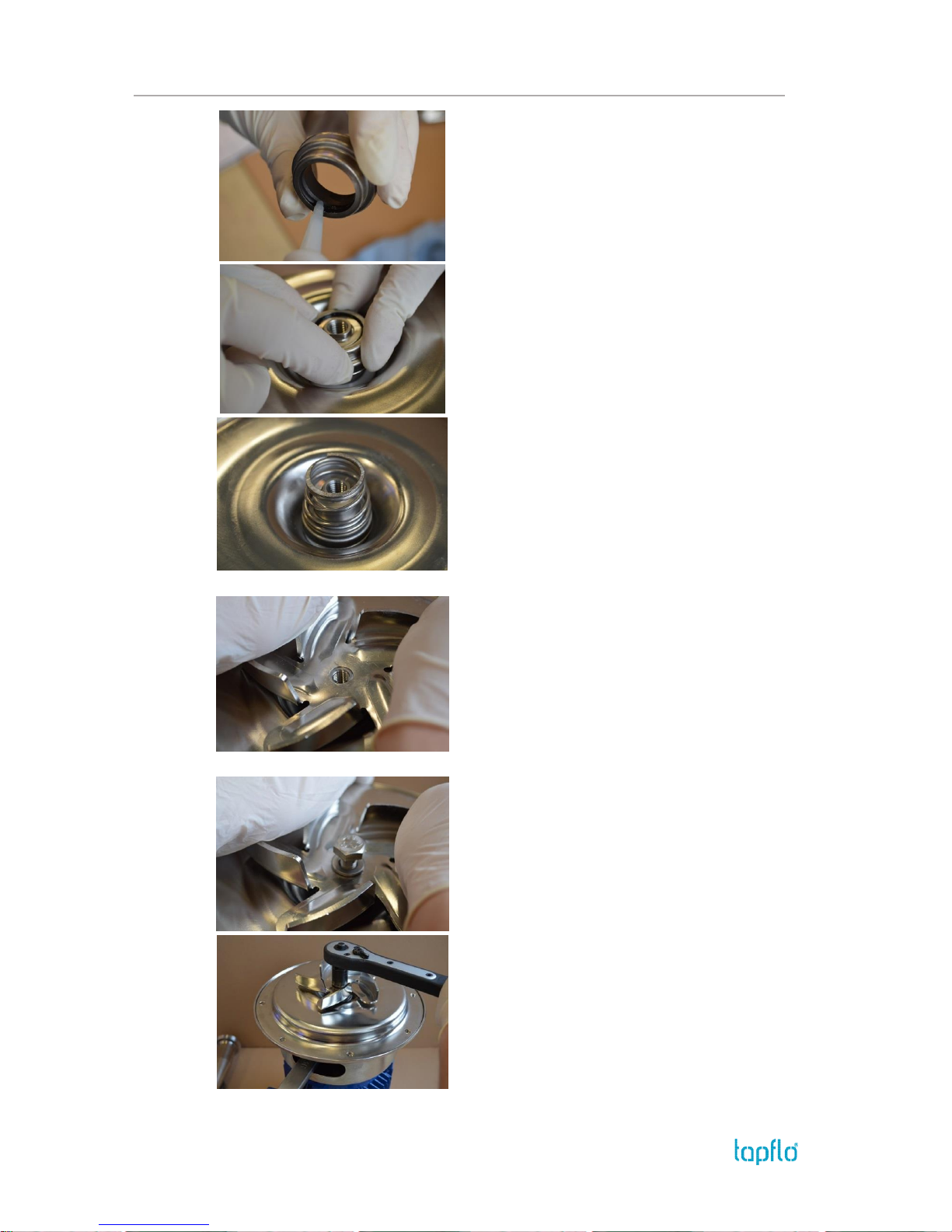
Fig. 3.4.13
Put a few drops of alcohol on the dynamic part Oring before mounting on shaft extension [16].
Fig. 3.4.14
Evenly pressing, place the dynamic part of the
mechanical seal [15A] onto the shaft extension [16].
Fig. 3.4.15
Assembly the spring of the mechanical seal.
Fig. 3.4.16
Evenly with both hands press the impeller [9…] onto
the shaft extension [16].
When mounting the impeller [9…] on the shaft
extension [16] make sure that it is locked in the
proper position before tightening the mounting
screw [191] with its washer [192].
NOTE! Take care not to damage the head surface of
the shaft extension.
Fig. 3.4.17
When assembling the washer [192] remember to
face the flat surface towards the impeller [9…]. Fit the
mounting screw [191] into the shaft extension [16].
Fig. 3.4.18
For tightening the mounting screw [191], use a
spanner key in the opening of the pump back cover
[11] to hold the shaft [16].
Page 23
3. MAINTENANCE
IOM manual CTI & CTH centrifugal pumps 23
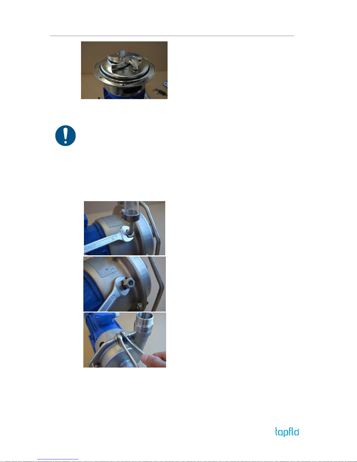
Fig. 3.4.19
When assembling the casing, make sure that the Oring sealing surfaces on the casing [13] and the back
casing [12] are clean.
3.4.1. Test run
We recommend you to conduct a test run of the pump before installing it in the system, so
no liquid gets wasted if the pump leaks or perhaps does not start accordingly to wrong
assembly of the pump.
After a few weeks of operation retighten the screws with appropriate torque.
3.5. Disassembly – 4FZ option
Please follow below instructions in order to perform the disassembly of the lubricated and
flushed seal option in our CT pumps.
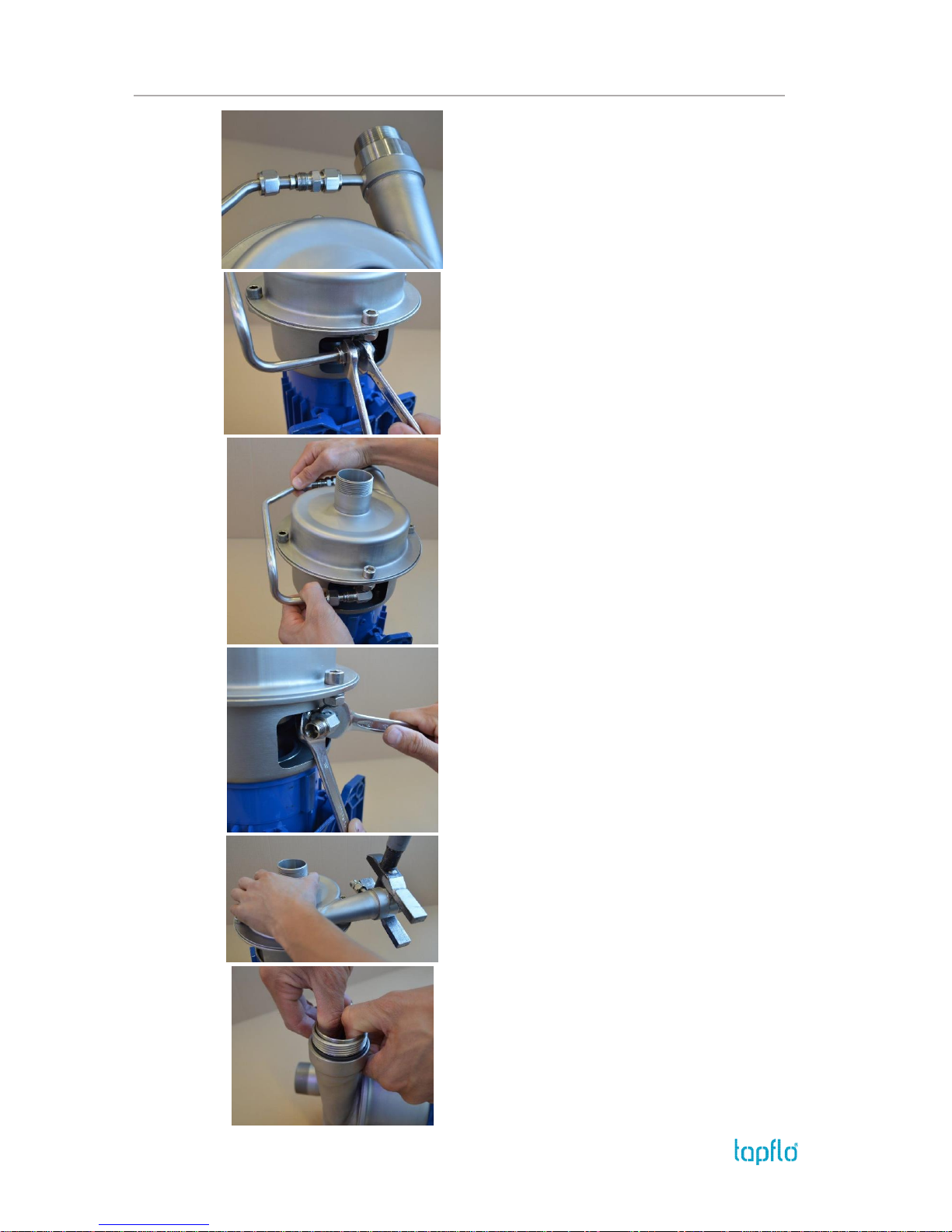
Fig. 3.5.1
Loosen the screw holding the oil reservoir [62] and
remove it.
Fig. 3.5.2
Unscrew the straight union form the back casing
[126].
Fig. 3.5.3
Loosen the screw on the straight union [1366].
Page 24
3. MAINTENANCE
IOM manual CTI & CTH centrifugal pumps 24
Fig. 3.5.4
Release the metal pipe [1363].
Fig. 3.5.5
Loosen the screw on the elbow union [1367].
Fig. 3.5.6
Remove the metal pipe [1363].
Fig. 3.5.7
Unscrew and remove the elbow union [1367].
Fig. 3.5.8
Unscrew the connection adaptor [1364].
Fig. 3.5.9
Take out the strainer [1361] and the O-ring [1365].
Page 25
3. MAINTENANCE
IOM manual CTI & CTH centrifugal pumps 25
Fig. 3.5.10
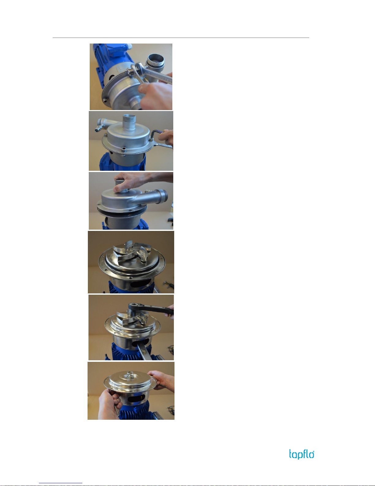
Unscrew the straight union [1366].
Fig. 3.5.11
Unscrew the casing mounting screws [141] and
remove them with the nuts [143] and washers [142].
Fig. 3.5.12
Take off the pump casing [136].
Fig. 3.5.13
Remove the O-ring [18].
NOTE! After every disassembly the O-ring [18] has
to be replaced by a new one.
Fig. 3.5.14
Remove the impeller mounting screw [191] and the
washer [192], use a spanner key in the opening of the
pump back cover [1146] to hold the shaft [16Z]
during assembly and disassembly of the impeller.
Remove the impeller.
Fig 3.5.15
Carefully remove the back casing [126]. The static
part [15B] of the mechanical seal will remain in the
back casing.
Page 26
3. MAINTENANCE
IOM manual CTI & CTH centrifugal pumps 26
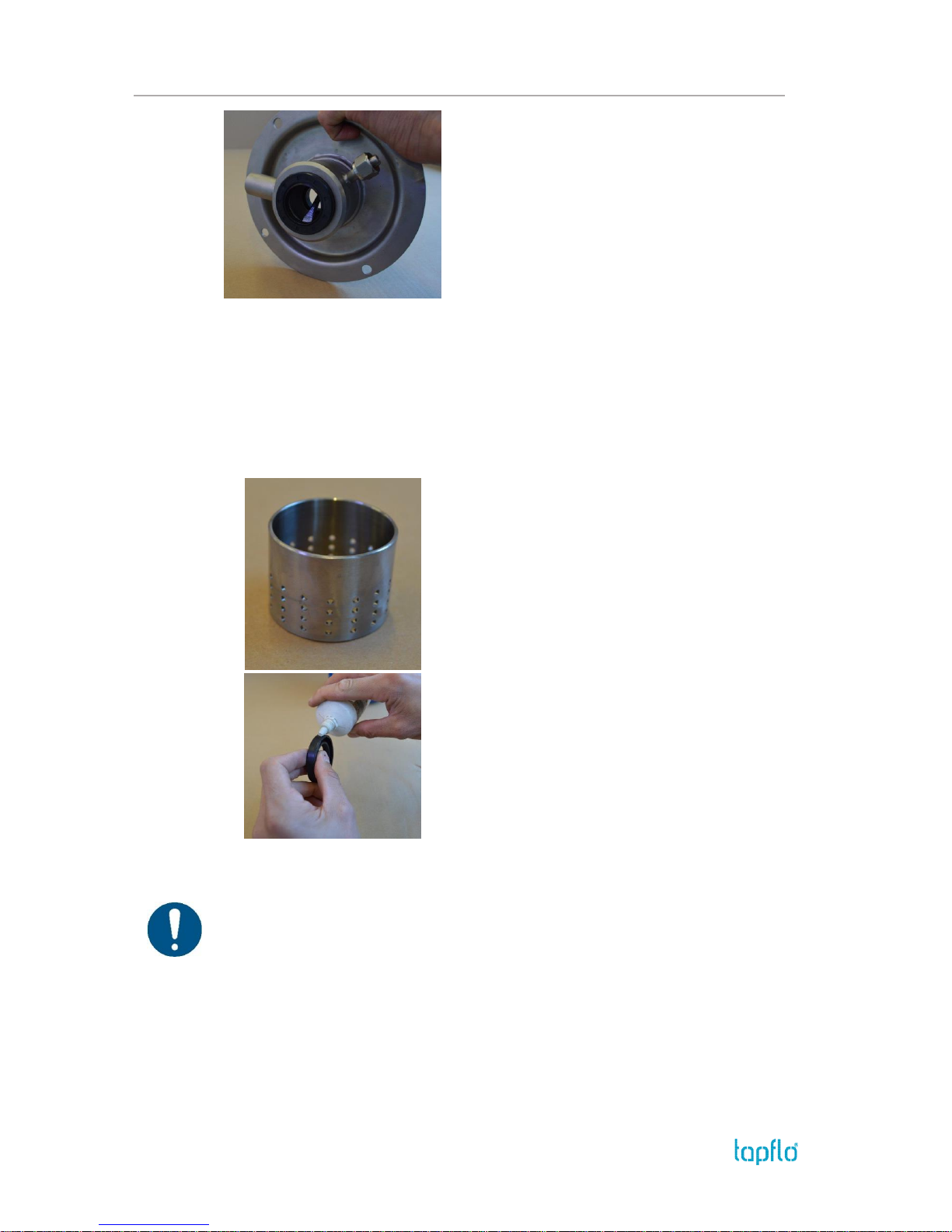
Lubricated seal (4Z) only!
Fig. 3.5.16
If necessary remove the lip seal [159].
3.6. Assembly – 4FZ option
The assembly procedure is done in the reverse order to the disassembly.
Nevertheless there are a few things that you have to remember in order to assemble the
pump correctly.
Fig. 3.6.1
Check if the strainer [1361] is not clogged and clean
if necessary.
Fig. 3.6.2
Before inserting the lip seal [159] into the back casing
[126] wet it with alcohol. Use a pressing device to
insert the lip seal.
3.6.1. Test run
We recommend you to conduct a test run of the pump before installing it in the system, so
no liquid gets wasted if the pump leaks or perhaps does not start accordingly to wrong
assembly of the pump.
After a few weeks of operation retighten the screws with appropriate torque.
Page 27
4. OPTIONS
IOM manual CTI & CTH centrifugal pumps 27
4. OPTIONS
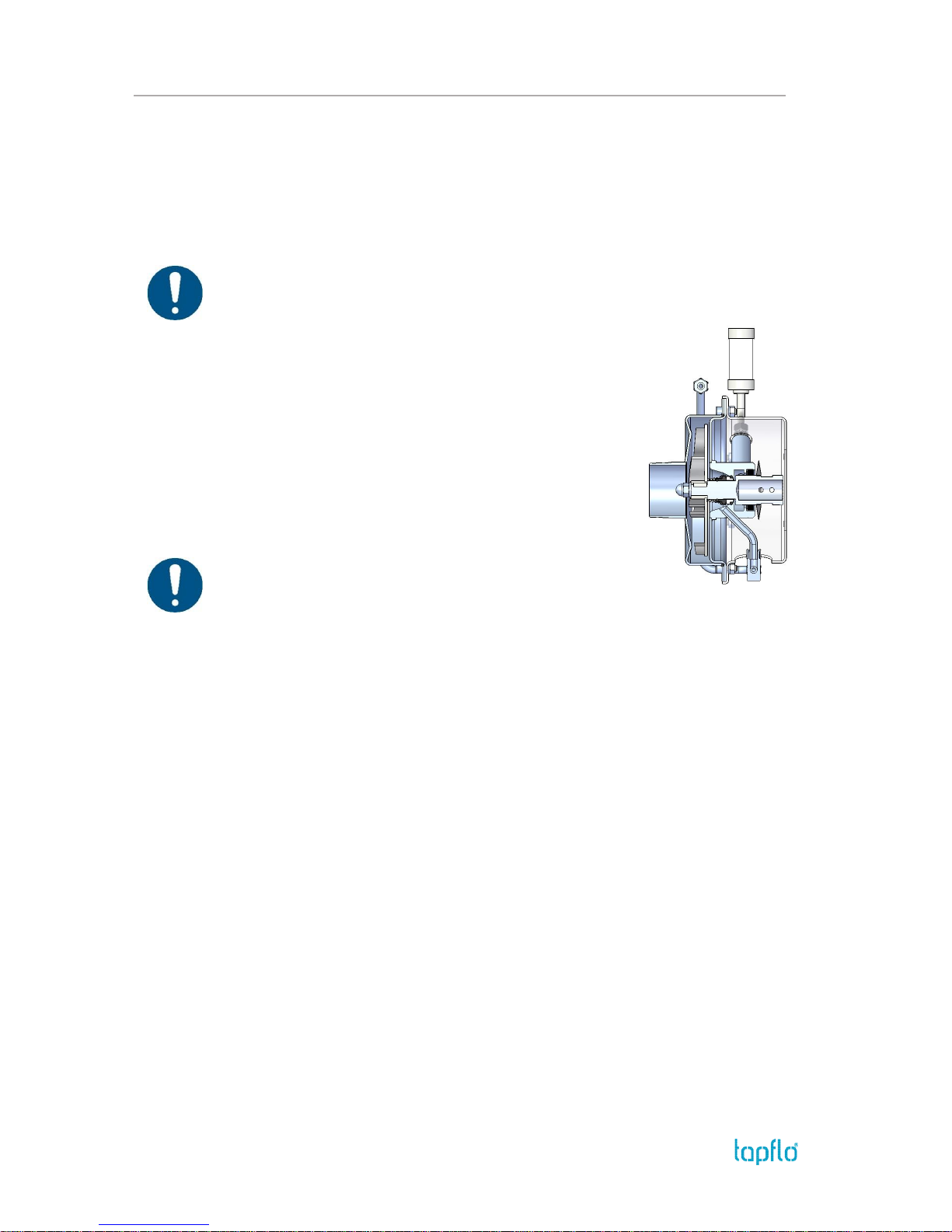
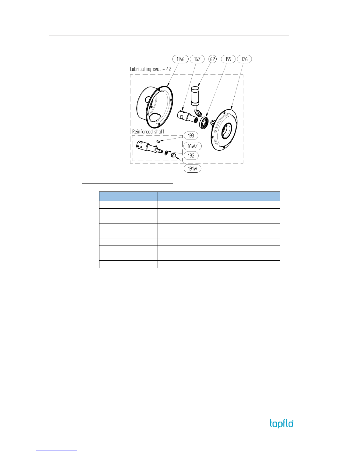
4.1. Lubricated seal – 4Z
A great option when there is a potential risk of dry running, or where the product tends to
solidify or crystallize. An oil reservoir is connected to the mechanical seal chamber.
The pump is delivered without lube medium in oil reservoir!
Before the first start fill up the oil reservoir with a proper
medium (i.e. SAE 20 oil). In case if the pumped medium
cannot be contaminated by oil, you should use a
lubricating medium compatible with the pumped medium;
Medium in the oil reservoir should be also compatible with
materials that the pump is made of (when using oil as
buffering liquid you should not use EPDM O-rings in
mechanical seal);
As a standard, an NBR lip seal is used (other materials are
available upon request);
Oil reservoir should be filled up to ¾ of cup height;
You should change liquid after 2000 hours of operation or
once a year.
For food applications it is recommended to use FDA approved liquid.
Important!
If mechanical seal damage will occur, fluid level in the chamber will increase and then it
will spill out of the oil reservoir. You must stop the pump immediately to replace
mechanical seal!
If liquid level in oil reservoir will start decreasing in short period of time, probably the
lip seal is damaged. You should stop the pump and replace damaged lip seal.
Page 28
4. OPTIONS
IOM manual CTI & CTH centrifugal pumps 28
Additional / different parts:
Available for pump sizes: C, D and E
Art. no
Q-ty
Description
5-xxx-1146
1
Pump back cover for lubricated seal
5-xxx-126
1
Pump back casing with welded seal chamber
5-xxx-159
1
Lip seal
5-xxx-16Z
1
Shaft for pump with lubricated seal
5-xxx-16WZ*
1
Shaft – reinforced version
5-xxx-62
1
Oil reservoir
5-xxx-191W*
1
Domed nut for reinforced shaft
5-xxx-192*
1
Washer for reinforced shaft
5-xxx-193*
1
Key for reinforced shaft
* Option
Page 29
4. OPTIONS
IOM manual CTI & CTH centrifugal pumps 29
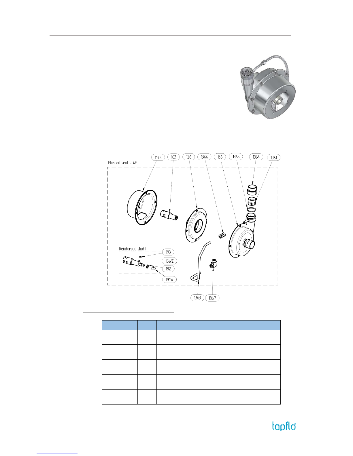
4.2. Flushed seal – 4F (API Plan 11)
When abrasive or sticky particles are present, it’s
recommended to use a flushed seal system. A small amount of
the pumped product is recirculated from the discharge side to
the seal chamber to flush solids cumulated in it. It helps to save
mechanical seal (15) and back casing (12) from being worn. In
addition a self-cleaning filter is used at the discharge.
Flushed seal pipe work is fully demountable. To disassemble
self-cleaning filter for removal of collected “big” particles or
routine inspections, remove upper flange and then disassemble the filter. To provide easy
disassembly the flushing steel pipe line is fixed with gas fittings.
Additional / different parts:
Available for pump sizes: C, D and E
Art. no
Q-ty
Description
5-xxx-1146
1
Pump back cover for flushed seal
5-xxx-126
1
Pump back casing with welded seal chamber
5-xxx-136
1
Pump cover for flushed seal
5-xxx-1361
1
Strainer
5-xxx-1363
1
Metal pipe
5-xxx-1364
1
Connection adaptor
5-xxx-1365
1
Adaptor O-ring
5-xxx-1366
1
Straight union
5-xxx-1367
1
Elbow union
5-xxx-16Z
1
Shaft
Page 30
4. OPTIONS
IOM manual CTI & CTH centrifugal pumps 30
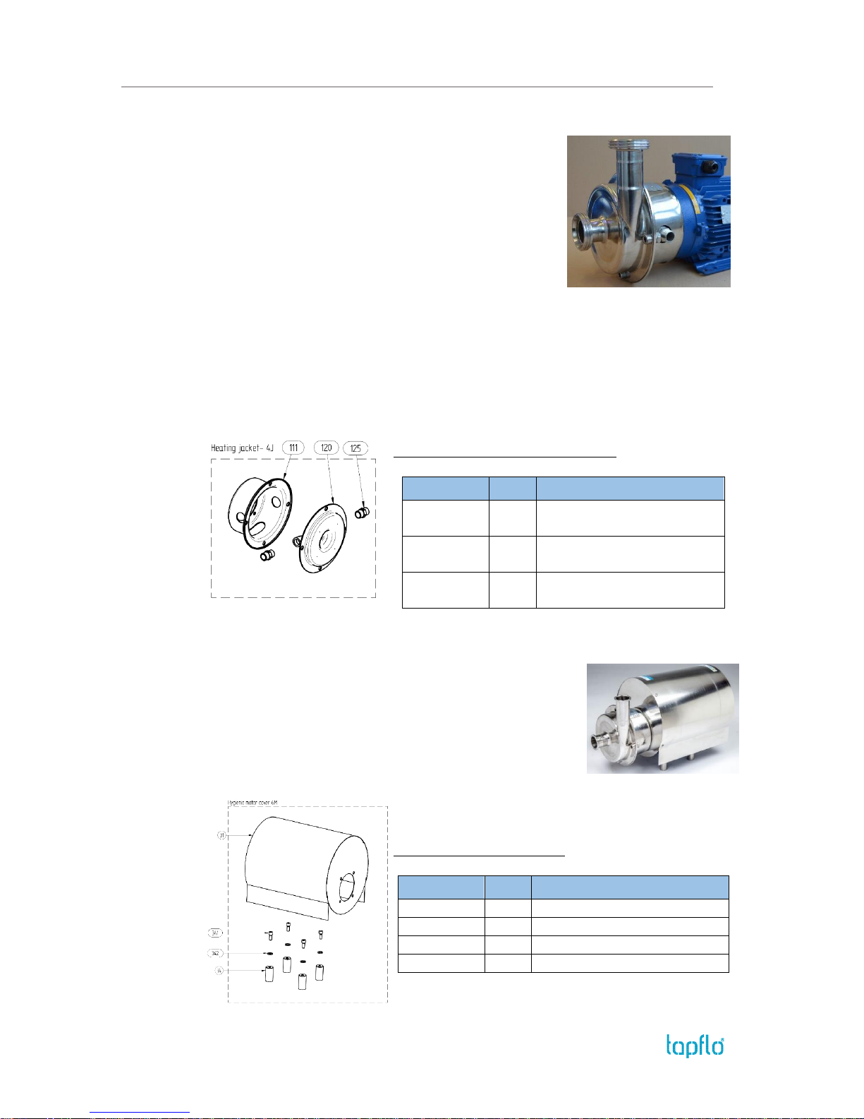
4.3. Heating / cooling jacket – 4J
Great protection for the mechanical seal in cases where there
is a risk of solidification of the product. The heating jacket is
also used when the pumped product has to maintain a
specific temperature, high or low. A heating or cooling
medium is continuously circulated in the jacket.
Heating / cooling is operated by a jacket welded into the
pump back casing (12). The jacket has two G ½” connections.
To connect the jacket use flexible hoses to prevent any undue
stress and strain on the heating jacket connectors.
For heating / cooling process use medium that is fully compatible with materials the pump
is made of. Maximum temperature for heating medium is 60°C, maximum pressure is 2 bar.
It’s crucial to avoid sudden temperature changes that could cause excessive strain.
The pump can also be equipped with optional connections on the heating jacket (e.g.
flanges).
Additional / different parts:
Available for pump sizes: C, D and E
Art. no
Q-ty
Description
5-xxx-111
1
Pump back cover for heating
jacket
5-xxx-120
1
Pump back casing with
heating jacket
5-xxx-125
2
Joint for pump with heating
jacket
4.4. Hygienic shroud – M
An optional motor shroud is available. It is made of stainless
steel and provides easy cleaning and splash protection for the
electrical motor. As a standard, the pump is equipped with feet.
Additional / different parts:
Available for all pump sizes
Art. no
Q-ty
Description
5-xxx-31
1
Hygienic pump shroud
5-xxx-34
4
Shroud foot
5-xxx-341
4
Shroud foot screw
5-xxx-342
4
Shroud foot screw washer
Page 31
4. OPTIONS
IOM manual CTI & CTH centrifugal pumps 31
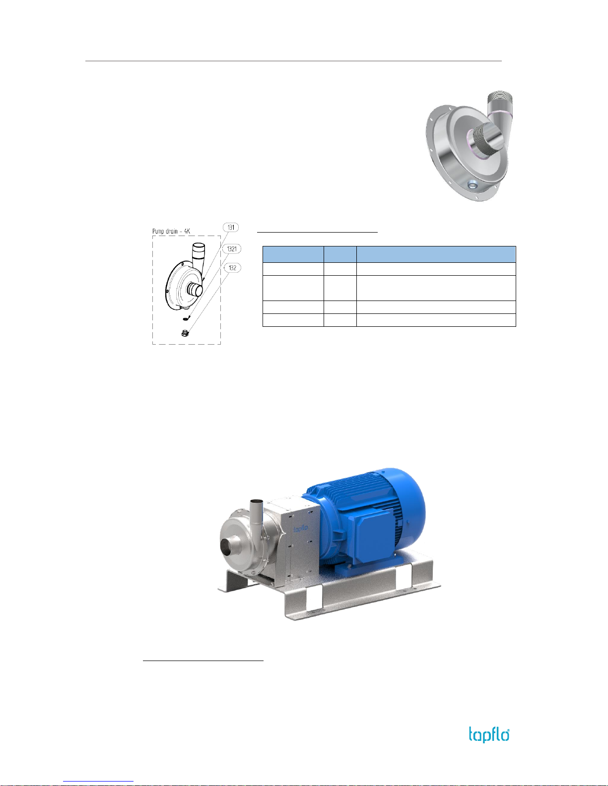
4.5. Pump drain – 4K
To allow easy draining, the pump casing can be designed with a
drain and drain plug. To empty the pump just remove the plug and
the casing will drain automatically.
As a standard, the drain has a G 3/8” threaded connection. Optional
connections like Tri-clamp or hygienic thread can be fitted instead.
Additional / different parts:
Available for all pump sizes
Art. no
Q-ty
Description
5-xxx-131
1
Pump casing with drain
5-xxx-131(x)
1
Pump casing with drain;
x – nonstandard drain plug and size
5-xxx-132
1
Drain plug
5-xxx-1321
1
Drain plug O-ring
4.6. Long coupled execution – B
Long coupled execution is a perfect solution when pumping hot products like oil at
temperatures up to 180°C.
Complete pump unit is mounted on baseplate, with coupling, bearing and guard. Usage of
additional bearing also provides more stable work for the pump unit.
Available for all pump sizes
For spare parts drawing and list please refer to chapter
5.5. Spare parts – long coupled execution
Page 32
4. OPTIONS
IOM manual CTI & CTH centrifugal pumps 32
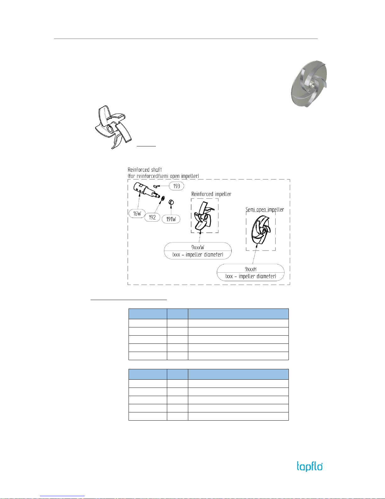
4.7. Semi-open impeller – 4H; Reinforced impeller – 4W
Tapflo CT pumps can be fitted with a semi-open impeller in comparison to
its standard open impeller. This option ensures more stable operation, lower
noise, lower vibrations and more robust construction. It is recommended to
use the semi-open impeller when hard solids can be present in the pumped
liquid. This impeller is always in reinforced execution.
The reinforced impeller is a great option when pumping high viscous
liquids or ones containing solid particles. This design is much more robust
and can withstand more tensions transferred from the liquid.
NOTE! The D, F and G size impellers are reinforced as standard.
Additional / different parts:
Available for all pump sizes
Art. no
Q-ty
Description
5-xxx-9xxxH
1
Semi-open impeller
5-xxx-16W
1
Reinforced shaft
5-xxx-191W
1
Domed nut for impeller
5-xxx-192
1
Washer
5-xxx-193
1
Mounting key
Art. no
Q-ty
Description
5-xxx-16W
1
Reinforced shaft
5-xxx-9xxxW
1
Reinforced impeller
5-xxx-191W
1
Domed nut for impeller
5-xxx-192
1
Washer
5-xxx-193
1
Mounting key
Page 33
4. OPTIONS
IOM manual CTI & CTH centrifugal pumps 33
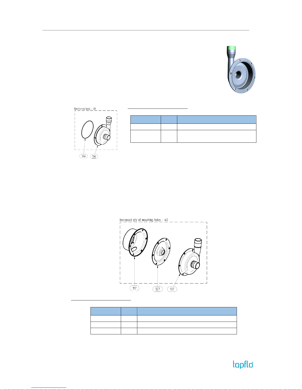
4.8. Reinforced pump casing – 4B
This option is perfect for CT pumps when the pumped liquid has high
penetration properties like paraffin.
4B stands for reinforced front cover which has special groove for O-ring.
4O is for increased number of mounting holes in pump casing, back cover
and back casing.
Additional / different parts:
Available for all pump sizes
Art. no
Q-ty
Description
5-xxx-13W
1
Reinforced pump casing
5-xxx-18W
1
Housing O-ring for reinforced
casing
4.9. Increased number of mounting holes – 4O
This options is perfect for CT pumps when the pumped liquid has high penetration
properties like paraffin.
4O is for increased number of mounting holes in pump casing, back cover and back casing.
Additional / different parts:
Available for all pump sizes
Art. no
Q-ty
Description
5-xxx-117
1
Pump back cover with increased no of holes
5-xxx-127
1
Pump back casing with increased no of holes
5-xxx-137
1
Pump casing with increased no of holes
Page 34
4. OPTIONS
IOM manual CTI & CTH centrifugal pumps 34
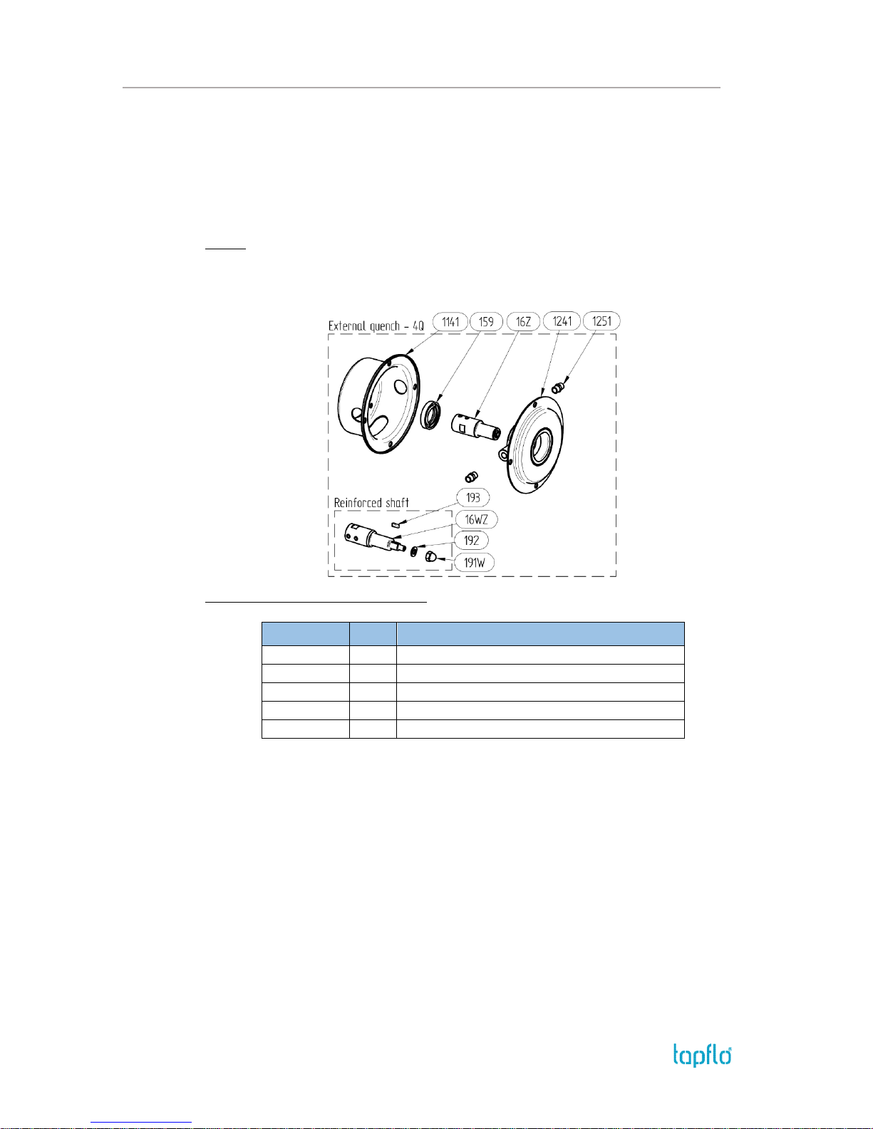
4.10. External quench – 4Q
This option is similar to the lubricated seal option and is recommended when there is a
potential risk of dry running, or where the product tends to solidify or crystallize when in
contact with air. There is however an added value to this option, as circulating quench liquid
removes heat from the mechanical seal. It is recommended to use a thermos-siphon
circulation method in the quench circuit.
NOTE! Max pressure in the quench circuit is 0,5 bar.
Additional / different parts:
Available for pump sizes C, D and E
Art. no
Q-ty
Description
5-xxx-1141
1
Pump back cover for external quench
5-xxx-1241
1
Pump back casing for external quench
5-xxx-1251
2
Connection joint
5-xxx-159
1
Lip seal
5-xxx-16Z
1
Pump shaft for external quench
4.11. Mechanical seal options
Apart from different materials that can be used for static and dynamic seal faces as well as
elastomers (see 6.1 “Pump code”) we offer a range of different special execution mechanical
seals:
2P – in this potion the O-ring of the static part of the mechanical seal is replaced
by an OP-ring (square O-ring). This increases friction between the O-ring and the
back casing thus lowering chances of static part rotation when seal faces stick
together.
2K – this option refers only to SiC/SiC mechanical seals. Standard seals have seal
faces of the same hardness therefore there is potential risk of them sticking
together due to adhesion phenomena. 2K offers seal faces of different hardness
(J/D) thus eliminating this risk. Additionaly seal is equipped with OP-ring.
Page 35
5. SPARE PARTS
IOM manual CTI & CTH centrifugal pumps 35
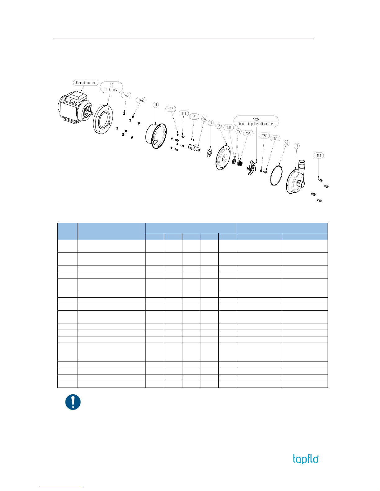
5. SPARE PARTS
5.1. Spare parts drawing
5.2. Spare parts list
Pos.
Description
Size
Material
CT A
CT B
CT C
CT D
CT E
CT I
CT H
11
Back cover [H/N]*
1 1 1 1 1
AISI 316L Glass
blasted
AISI 316L Ra<0.8
12
Back casing [H/N]
1 1 1 1 1
AISI 316L Glass
blasted
AISI 316L Ra<0.8
121
Back cover mounting screws
4 4 4 4 4
A4-70
A4-70
122
Back cover mounting washers
4 4 4 4 4
A4-80
A4-80
13
Pump casing [H/N]
1 1 1 1 1
AISI 316L Glass
blasted
AISI 316L Ra<0.8
141
Casing mounting screws
4 4 4 8 8
A4-70
A4-70
142
Casing mounting washers
4 4 4 8 8
A4-80
A4-80
143
Casing mounting nuts
4 4 4 8 8
A4-70
A4-70
15
Mechanical seal (complete)
[H/N]
1 1 1 1 1
See 6.1
See 6.1
16
Shaft extension
1 1 1 1 1
AISI 316L
AISI 316L
161
Lock screw
1 1 2 2 2
A2-70
A2-70
17
Deflector
1 1 1 1 1
NBR
NBR
18
Casing O-ring [H/N]
1 1 1 1 1
EPDM (std), FKM,
FEP/Silicone, NBR
EPDM FDA (std),
FKM FDA,
FEP/SIlicone FDA
191
Impeller mounting screw
1 1 1 1 1
A4-70
A4-70
192
Impeller mounting washer
1 1 1 1 1
A4-70
A4-70
60
Motor adaptive flange
- - - - 1
Aluminium
Aluminium
9xxx
Impeller (xxx – diameter)
1 1 1 1 1
AISI 316L Ra<0,8
AISI 316L Ra<0.8
* Parts indicated as [H/N] have different execution for CT I and CT H pumps. When ordering spare parts please
indicate if the part is for Industrial or Hygienic series e.g. 5-340N-11 or 5-340H-11.
Page 36
5. SPARE PARTS
IOM manual CTI & CTH centrifugal pumps 36
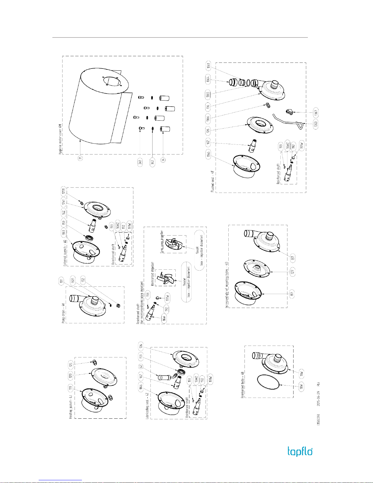
5.3. Spare parts drawing - options
Page 37

5. SPARE PARTS
IOM manual CTI & CTH centrifugal pumps 37
5.4. Spare parts list - options
Lubricated seal – 4Z
Art. no
Q-ty
Description
5-xxx-1146
1
Pump back cover for lubricated seal
5-xxx-126
1
Pump back casing with welded seal
chamber
5-xxx-159
1
Lip seal
5-xxx-16Z
1
Shaft for pump with lubricated seal
5-xxx-16WZ*
1
Shaft – reinforced version
5-xxx-62
1
Oil reservoir
5-xxx-191W*
1
Domed nut for reinforced shaft
5-xxx-192*
1
Washer for reinforced shaft
5-xxx-193*
1
Key for reinforced shaft
* Option
Flushed seal – 4F
Art. no
Q-ty
Description
5-xxx-1146
1
Pump back cover for flushed seal
5-xxx-126
1
Pump back casing with welded seal
chamber
5-xxx-136
1
Pump cover for flushed seal
5-xxx-1361
1
Strainer
5-xxx-1363
1
Metal pipe
5-xxx-1364
1
Connection adaptor
5-xxx-1365
1
Adaptor O-ring
5-xxx-1366
1
Straight union
5-xxx-1367
1
Elbow union
5-xxx-16Z
1
Shaft
Heating jacket – 4J
Art. no
Q-ty
Description
5-xxx-111
1
Pump back cover for heating jacket
5-xxx-120
1
Pump back casing with heating jacket
5-xxx-125
2
Joint for pump with heating jacket
External quench – 4Q
Art. no
Q-ty
Description
5-xxx-1141
1
Pump back cover for external
quench
5-xxx-1241
1
Pump back casing for external
quench
5-xxx-1251
2
Connection joint
5-xxx-159
1
Lip seal
5-xxx-16Z
1
Pump shaft for external quench
Hygienic shroud - M
Art. no
Q-ty
Description
5-xxx-31
1
Hygienic pump shroud
5-xxx-34
4
Shroud foot
5-xxx-341
4
Shroud foot screw
5-xxx-342
4
Shroud foot screw washer
Pump drain – 4K
Art. no
Q-ty
Description
5-xxx-131
1
Pump casing with drain
5-xxx-131(x)
1
Pump casing with drain;
x – nonstandard drain plug and size
5-xxx-132
1
Drain plug
5-xxx-1321
1
Drain plug O-ring
Semi-open impeller – 4H
Reinforced impeller – 4W
Art. no
Q-ty
Description
5-xxx-9xxxH
1
Half open impeller
5-xxx-9xxxW
1
Reinforced impeller
5-xxx-16W
1
Reinforced shaft
5-xxx-191W
1
Domed nut for impeller
5-xxx-192
1
Washer
5-xxx-193
1
Mounting key
Reinforced pump casing – 4B
Increased number of mounting holes – 4O
Art. no
Q-ty
Description
5-xxx-117
1
Back cover - increased no of holes
5-xxx-127
1
Back casing - increased no of holes
5-xxx-137
1
Casing - increased no of holes
5-xxx-13W
1
Reinforced pump casing
5-xxx-18W
1
Housing O-ring for reinforced casing
Page 38
5. SPARE PARTS
IOM manual CTI & CTH centrifugal pumps 38
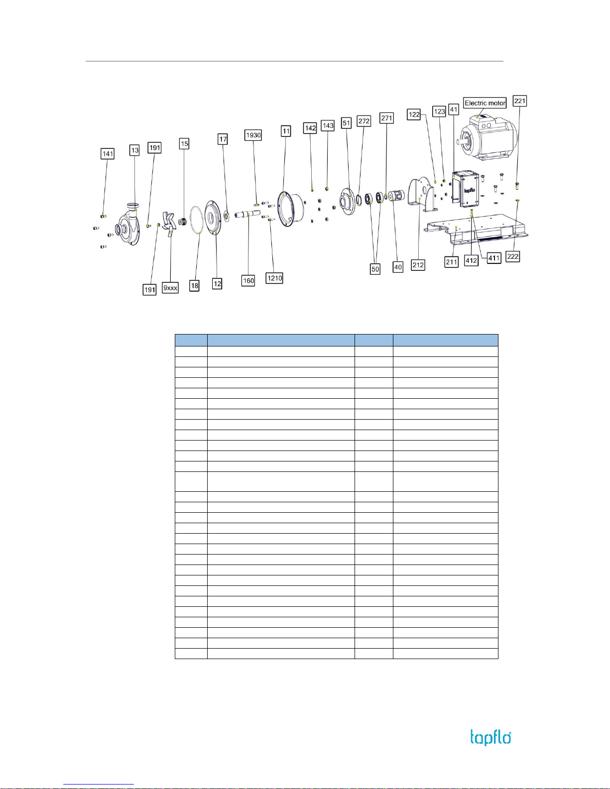
5.5. Spare parts – long coupled execution
5.6. Spare parts list – long coupled execution
Pos.
Description
Q-ty
Material
11
Back cover
1
AISI 316L
12
Back casing
1
AISI 316L
1210
Back cover mounting screws
4
A4-70
122
Back cover mounting washer
4
A4-70
123
Back cover mounting nut
4
A4-70
13
Pump casing
1
AISI 316L
141
Casing mounting screws
4 / 8*
A4-70
142
Casing mounting washers
4 / 8*
A4-80
143
Casing mounting nuts
4 / 8*
A4-70
15
Mechanical seal (complete)
1
See 6.1
160
Shaft for long coupled pump
1
AISI 316L
17
Deflector
1
NBR
18
Casing O-ring
1
EPDM FDA (std), FKM FDA,
FEP/Silicone FDA
191
Impeller mounting screw
1
A4-70
192
Impeller mounting washer
1
A4-70
1930
Key for shaft
1
A4
211
Base plate for pump assembly
1
AISI 304L
212
Pump bracket
1
AISI 304L
221
Motor mounting screw
4
A4-70
222
Motor mounting nut
4
A4-70
271
Bearing circlip towards motor
1
Cr3 coated steel
272
Bearing circlip towards pump
1
Cr3 coated steel
40
Coupling
1
AISI 316Ti
41
Bearing cover
1
AISI 316L
411
Bearing cover mounting screw
4
A4-70
412
Bearing cover mounting washer
4
A4-70
50
Bearing
2
AISI 52100
51
Cover for bearing
1
AISI 316L
9xxx
Impeller (xxx – diameter)
1
AISI 316L Ra<0.8
* 4 for CT A, B and C size; 8 for CT D and E size
Page 39

5. SPARE PARTS
IOM manual CTI & CTH centrifugal pumps 39
5.7. Recommended spare parts
Normally the CT pump is maintenance free. However, depending on the nature of the liquid
and temperature etc. some parts of the pump are subject to wear and have to replaced. We
recommend having the following parts in stock:
Pos.
Description
Q-ty
15
Mechanical seal
1
18
Casing O-ring
1
5.8. How to order parts
When ordering spare parts for Tapflo pumps. please let us know what is the model number
and serial number from the pump’s name plate. Then just indicate the part numbers from
the spare parts list and quantity of each item.
Page 40
6. DATA
IOM manual CTI & CTH centrifugal pumps 40
6. DATA
6.1. Pump code
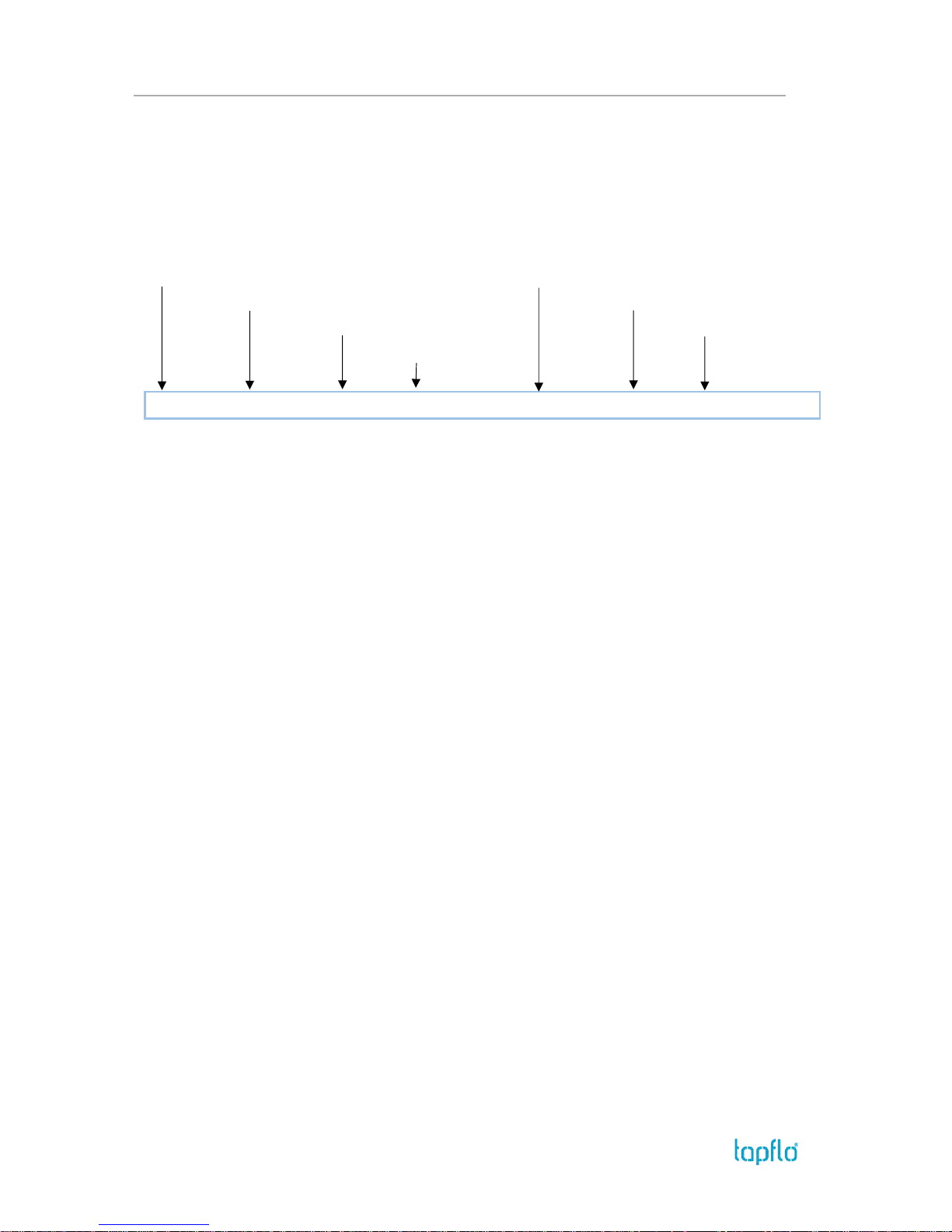
The model number on the pump and on the front page of this instruction manual tells the
pump size and materials of the pump.
I. Tapflo centrifugal pump
V. Pump options
II. Pump execution
VI. Motor power
III. Casing size
VII. Motor option
IV. Impeller size
CT I C
C-
1CGV3F-
02
M
I. CT = Tapflo centrifugal pump
II. Pump execution:
I = Industrial
H = Hygienic
III. Casing size (motor flange diameter / IEC size):
A = 105 mm / 71
B = 120 mm / 80
C = 140 mm / 90
D = 160 mm / 100 or 112
E = 200 mm / 132
IV. Impeller size
A = 90 mm
B = 98 mm
C = 125 mm
D = 130 mm (reinforced in standard)
E = 135 mm
F = 155 mm (reinforced in standard)
G = 180 mm (reinforced in standard)
V. Pump options:
1. Mechanical seal:
Blank* = ceramic/graphite/EPDM (FDA on CTH)
1CGV = ceramic/graphite/FKM (FDA on CTH)
1CGF = ceramic/graphite/FEP (FDA)
1CGN = ceramic/graphite/NBR (CTI only)
1SSE = SiC/SiC/EPDM (FDA on CTH)
1SSV = SiC/SiC/FKM (FDA on CTH)
1SSF = SiC/SiC/FEP (FDA)
1SSN = SiC/SiC/NBR (CTI only)
1SGE = SiC/graphite/EPDM (FDA on CTH)
1SGV = SiC/graphite/FKM (FDA on CTH)
1SGF = SiC/graphite/FEP (FDA)
1SGN = SiC/graphite/NBR (CTI only)
2. Mechanical seal type:
P = Standard mechanical seal with OP-ring
K = Different hardness of static and dynamic seal
elements – J/D with OP-ring (SiC/SiC only)
3. Connection options
Blank* = Thread BSP on CTI
Thread DIN 11851 on CTH
3A = ANSI flange (CTI only)
3B = BSPT thread (on CTH)
3C = Clamp ISO 2852 (CTH only)
3F = Flange DIN2633 PN 10/16
3T = Clamp DIN 32676 (CTH only)
3S = Thread SMS 1145 (CTH only)
3R = Thread RJT (CTH only)
3P = ISO 1127 clamp (CTH only)
3DA = DIN11866-1A thread (CTH only)
3X = Thread DIN 11851 (on CTI)
4. Special executions
4J = Pump with heating jacket
4F = Flushed seal
4Z = Lubricated seal
4H = Semi open heavy duty impeller (C-G sizes)
4K = Drain plug (3/8” BSP thread as standard)
4PX = Welds polishing (CTH only)
4W = Reinforced inmpeller (D and F sizes only)
4Q = External quench
4B = Reinforced front cover; special O-ring
4O = Increased number of mounting holes
VI. Motor power / IEC motor size
2900 rpm motors (2-pole):
03 = 0.37 kW / 71
05 = 0.55 kW / 71
07 = 0.75 kW / 80
15 = 1.5 kW / 90
22 = 2.2 kW / 90
40 = 4.0 kW / 112
55 = 5.5 kW / 132
60 = 6.0 kW / 112
75 = 7.5 kW / 132
110 = 11.0 kW / 160 (long coupled pump only)
1450 rpm motors (4-pole):
024 = 0.25 kW / 71
054 = 0.55 kW / 80
114 = 1.1 kW / 90
224 = 2.2 kW / 100
VII. Motor options
M = Hygenic motor shroud (CTS H)
B = Long coupled pump
P = Single phase motor
X2d = Eex d IIB T4 motor
X2e = Eex e IIB T3 motor
X3e = Ex II 3G T135C motor - tropic
T = Motor with PTC thermistor
V…F... = Motor for special voltage, frequency
* = standard execution
Page 41
6. DATA
IOM manual CTI & CTH centrifugal pumps 41
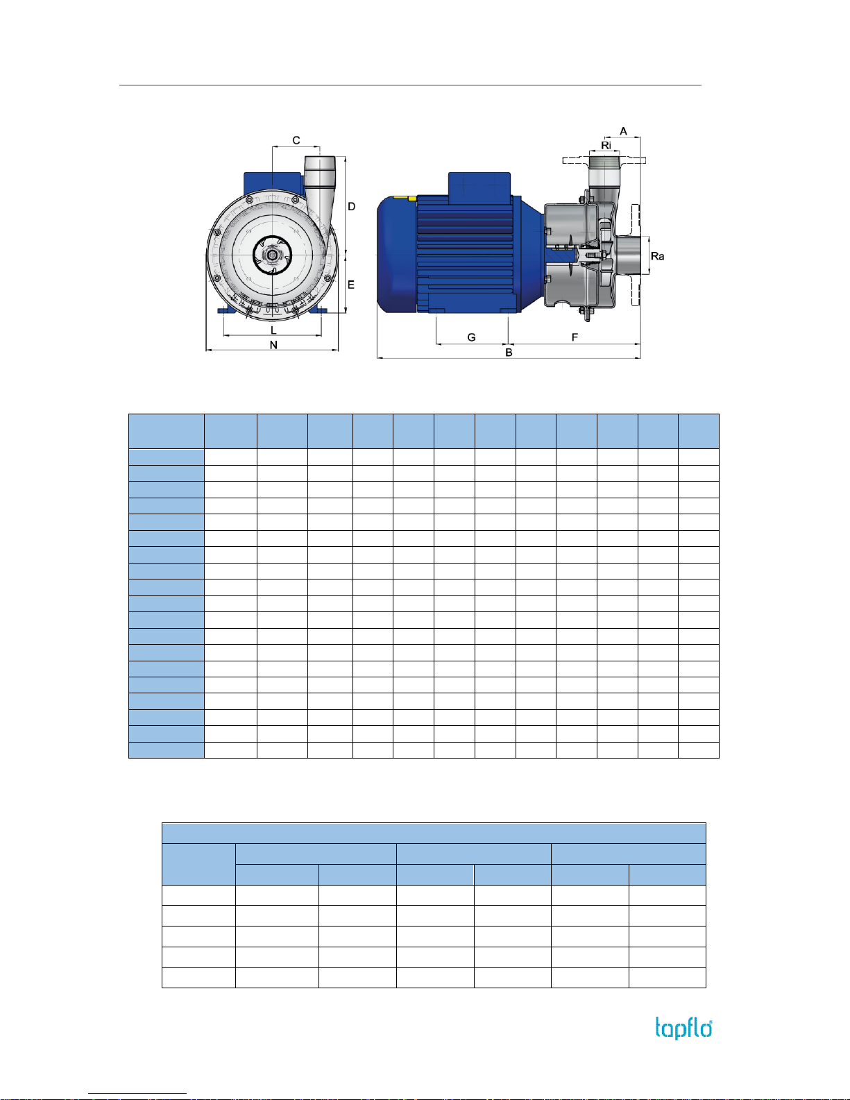
6.2. Dimensions - CTI
Dimensions in mm (where other is not indicated)
General dimensions only, ask us for detailed drawings. Changes reserved without notice.
MODEL
Motor
power
IEC
size
Weight
[kg]
A
B* C D E F
G*
L*
N
CTI AA-03
0.37
71
7.15
60
358
36
100
71
193
90
112
145
CTI AA-05
0.55
71
8.00
60
358
36
100
71
193
90
112
145
CTI BB-07
0.75
80
11.40
63
395
50
110
80
205
100
125
170
CTI CC-15
1.5
90
22.25
64
404
68
160
90
226
100
140
205
CTI CC-22
2.2
90
23.95
64
404
68
160
90
226
100
140
205
CTI CE-22
2.2
90
24.05
64
404
68
160
90
226
100
140
205
CTI DD-40
4.0
112
37.10
70
521
92
192
112
257
140
190
256
CTI DF-40
4.0
112
37.15
70
521
92
192
112
257
140
190
256
CTI EF-55
5.5
132
53.00
70
571
92
192
132
293
140
216
256
CTI EG-55
5.5
132
53.10
70
571
92
192
132
293
140
216
256
CTI EF-75
7.5
132
64.50
70
571
92
192
132
293
140
216
256
CTI EG-75
7.5
132
64.85
70
571
92
192
132
293
140
216
256
CTI AA-024
0.25
71
7.00
60
358
36
100
71
193
90
112
145
CTI BB-054
0.55
80
10.30
63
395
50
110
80
205
100
125
170
CTI CC-114
1.1
90
15.90
64
451
68
160
90
226
125
140
205
CTI CE-114
1.1
90
16.00
64
451
68
160
90
226
125
140
205
CTI DD-224
2.2
100
43.85
70
478
92
192
100
250
140
160
256
CTI DF-224
2.2
100
43.95
70
478
92
192
100
250
140
160
256
CTI DG-224
2.2
100
44.05
70
478
92
192
100
250
140
160
256
*The dimension may vary depending on motor brand
Connection dimensions
Model
BSPT male thread (std.)
DIN 2633 PN 16 flange
ANSI 150 flange
Ra
Ri
Ra
Ri
Ra
Ri
CTI A
1”
¾”
DN 25
DN 20
1”
¾”
CTI B
1 ½”
1”
DN 40
DN 25
1 ½”
1”
CTI C
1 ½”
1 ½”
DN 40
DN 40
1 ½”
1 ½”
CTI D
2 ½”
2”
DN 65
DN 50
2 ½”
2”
CTI E
2 ½”
2”
DN 65
DN 50
2 ½”
2”
Page 42
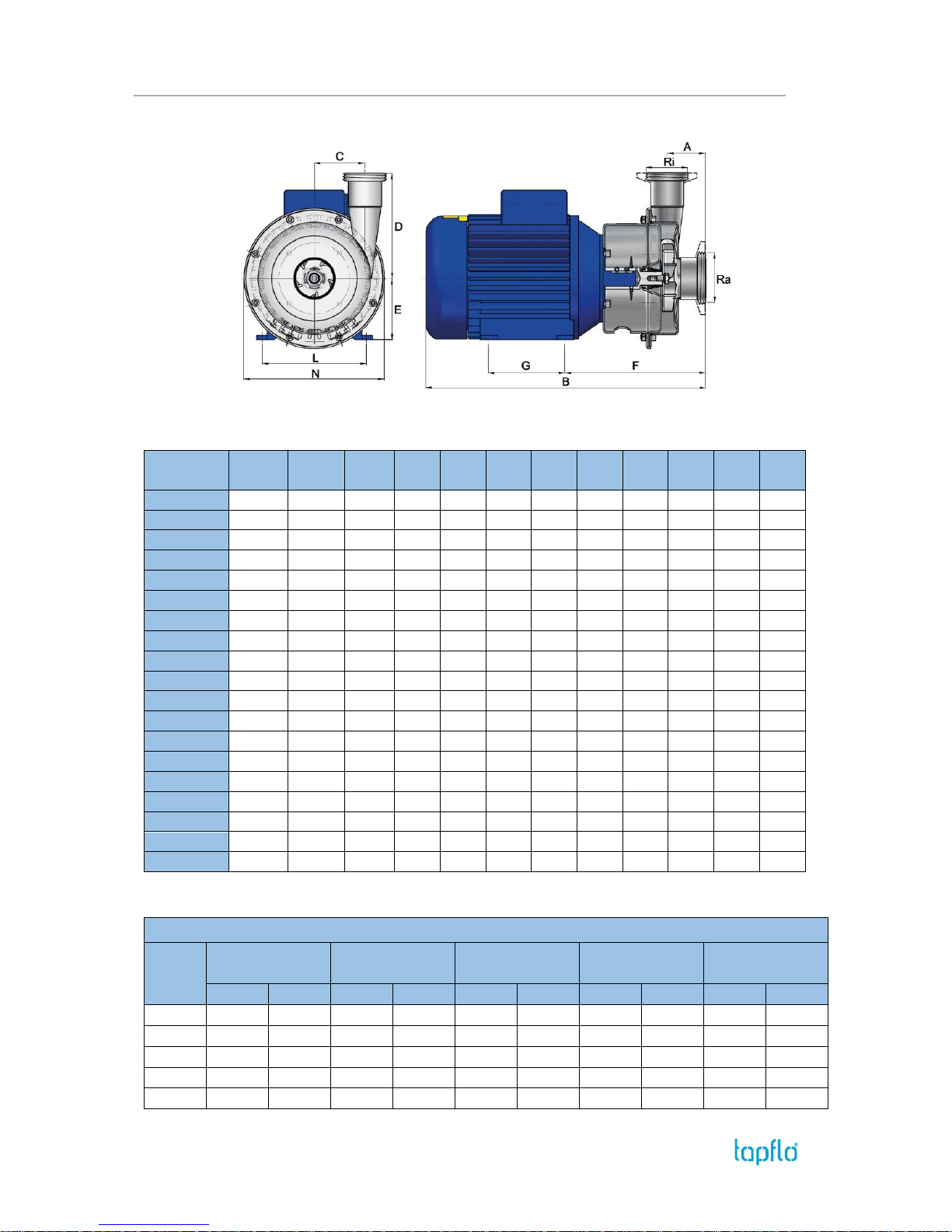
6. DATA
IOM manual CTI & CTH centrifugal pumps 42
6.3. Dimensions - CTH
Dimensions in mm (where other is not indicated)
General dimensions only, ask us for detailed drawings. Changes reserved without notice.
MODEL
Motor
power
IEC
size
Weight
[kg]
A
B* C D E F
G*
L*
N
CTH AA-03
0.37
71
7.35
60
358
36
100
71
193
90
112
145
CTH AA-05
0.55
71
8.00
60
358
36
100
71
193
90
112
145
CTH BB-07
0.75
80
11.40
63
395
50
110
80
205
100
125
170
CTH CC-15
1.5
90
22.35
64
429
68
160
90
226
125
140
205
CTH CC-22
2.2
90
24.10
64
429
68
160
90
226
125
140
205
CTH CE-22
2.2
90
24.15
64
429
68
160
90
226
125
140
205
CTH DD-40
4.0
112
37.05
70
479
92
192
100
251
140
160
256
CTH DF-40
4.0
112
37.10
70
479
92
192
100
251
140
160
256
CTH EF-55
5.5
132
53.30
70
571
92
192
132
293
140
216
256
CTH EG-55
5.5
132
53.40
70
571
92
192
132
293
140
216
256
CTH EF-75
7.5
132
64.80
70
571
92
192
132
293
140
216
256
CTH EG-75
7.5
132
65.15
70
571
92
192
132
293
140
216
256
CTH AA-024
0.25
71
7.25
60
358
36
100
71
197
90
112
145
CTH BB-054
0.55
80
15.80
63
395
50
110
80
205
100
125
170
CTH CC-114
1.1
90
15.85
64
451
68
160
90
226
125
140
205
CTH CE-114
1.1
90
15.90
64
451
68
160
90
226
125
140
205
CTH DD-224
2.2
100
32.20
70
478
92
192
100
250
140
160
256
CTH DF-224
2.2
100
32.30
70
478
92
192
100
250
140
160
256
CTH DG-224
2.2
100
32.40
70
478
92
192
100
250
140
160
256
*The dimension may vary depending on motor brand
Connection dimensions
Model
DIN 11851
thread (std.)
DIN 32676 clamp
ISO 2852 clamp
SMS 1145 thread
RJT thread
Ra
Ri
Ra
Ri
Ra
Ri
Ra
Ri
Ra
Ri
CTH A
DN 25
DN 25
DN 25
DN 20
38
25
38
25
1 ½”
1”
CTH B
DN 40
DN 32
DN 40
DN 25
38
25
51
38
1 ½”
1 ½”
CTH C
DN 40
DN 40
DN 40
DN 40
38
38
51
38
2”
2”
CTH D
DN 65
DN 50
DN 65
DN 50
70
51
63
51
3”
2”
CTH E
DN 65
DN 50
DN 65
DN 50
70
51
63
51
3”
2”
Page 43
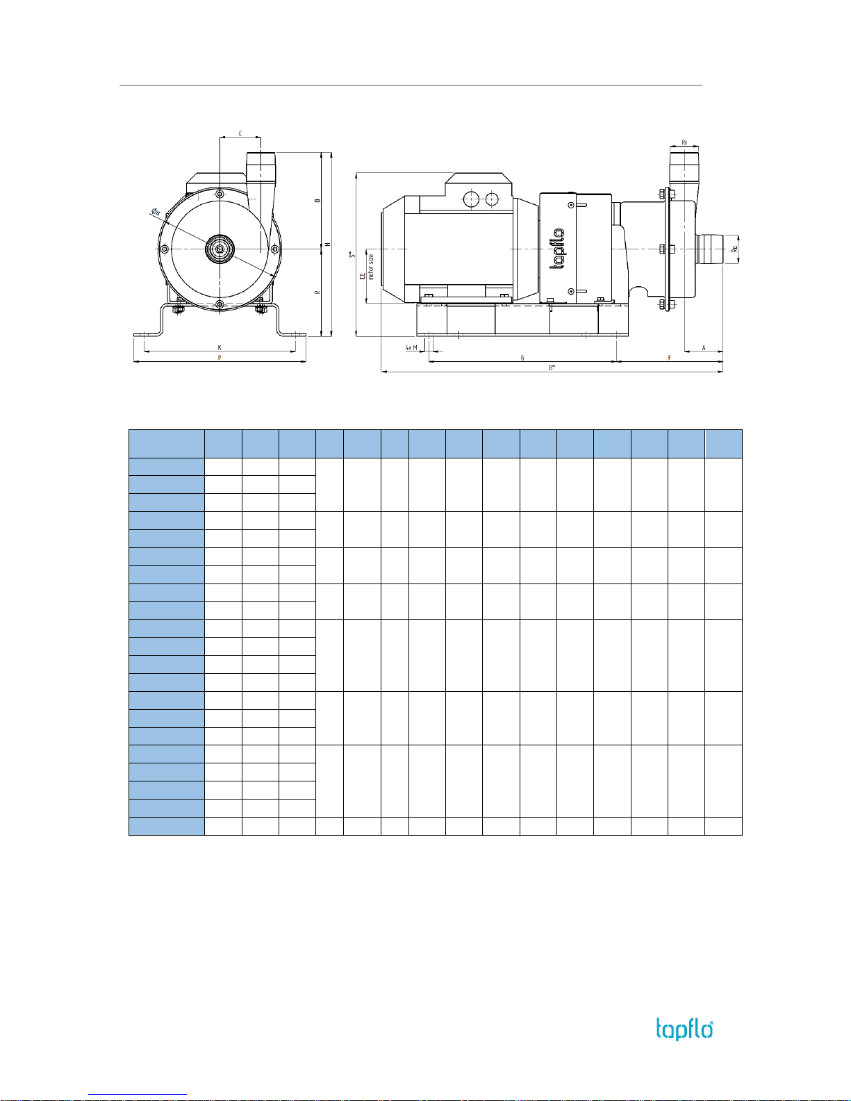
6. DATA
IOM manual CTI & CTH centrifugal pumps 43
6.4. Dimensions – CTI long coupled pump
Dimensions in mm (where other is not indicated)
General dimensions only, ask us for detailed drawings. Changes reserved without notice.
MODEL
Motor
power
IEC
size
Weight
[kg]
A
B* C D F G H K N P R S*
CTI AA-03B
0.37
71
60
485
36
100
155
310
225
250
143
285
125
223
CTI AA-05B
0.55
71
CTI AA-024B
0.25
71
CTI BB-07B
0.75
80
63
498
50
110
160
310
244
250
170
285
134
247
CTI BB-054B
0.55
80
CTI CC-15B
1.5
90S
64
540
68
160
177
310
304
250
205
285
144
270
CTI CE-15B
1.5
90S
CTI CC-22B
2.2
90L
64
565
68
160
177
310
304
250
205
285
144
270
CTI CE-22B
2.2
90L
CTI DD-40B
4.0
112M
70
666
92
192
200
370
359
350
256
400
167
303
CTI DF-40B
4.0
112M
CTI DF-60B
6.0
112M
CTI DG-60B
6.0
112M
CTI DD-224B
2.2
100L
72
630
92
192
200
370
347
350
256
400
155
291
CTI DF-224B
2.2
100L
CTI DG-224B
2.2
100L
CTI EF-55B
5.5
132S
70
746
92
192
200
370
379
350
256
400
187
355
CTI EG-55B
5.5
132S
CTI EF-75B
7.5
132S
CTI EG-75B
7.5
132S
CTI EG-110B
11.0
160M
70
881
92
192
260
490
448
416
256
466
256
522
* The dimension may vary depending on motor brand
M=13 mm for all pump sizes
Page 44
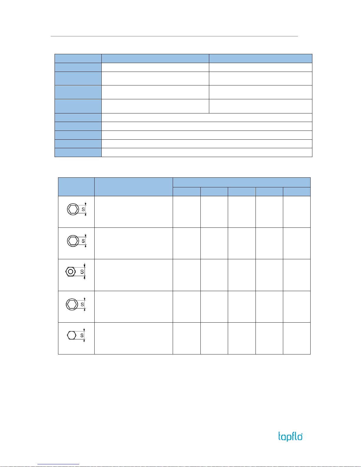
6. DATA
IOM manual CTI & CTH centrifugal pumps 44
6.5. Materials, data and limits
CTH …
CTI …
Casing
Stainless steel AISI 316L electro polished Ra<0.8
Stainless steel AISI 316L glass blasted
Impeller
Stainless steel AISI 316L electro polished Ra<0.8,
open (std) or semi-open
Stainless steel AISI 316L electro polished Ra<0.8,
open (std) or semi-open
Mechanical seal
Single ceramic/graphite (std), SiC/SiC or
SiC/graphite, optional with lube or flushing
Single ceramic/graphite (std), SiC/SiC or
SiC/graphite, optional with lube or flushing
O-rings
EPDM FDA approved (std), FEP/Silicone FDA
approved, FKM FDA approved
EPDM (std), FKM, FEP/Silicone or NBR
Motor
IP55; IEC frame B34; Available with ATEX cat 2 or 3; Eex e or Eex d
Pressure rating
10 bar (PN10)
Temperature
Max 90°C; 180°C for long coupled pump
Viscosity
Max ~200 cSt
Particles
Max diameter is 6 mm (std open impeller); bigger if soft particles
6.6. Mounting torques and dimensions of screws/nuts
Screw / nut
type
Description
Pump model
CT A …
CT B …
CT C …
CT D …
CT E …
Pos. 121. allen screw
Mounting torque [Nm]
Too size “S” [mm]
Thread
15
5
M6
15
5
M6
15
6
M8
15
6
M8
15
8
M10
Pos. 141. allen screw
Mounting torque [Nm]
Too size “S” [mm]
Thread
15
5
M6
15
5
M8
15
8
M10
15
6
M8
15
6
M8
Pos. 143. hexagonal nut
Mounting torque [Nm]
Too size “S” [mm]
Thread
15
5
M6
15
13
M8
15
17
M10
15
13
M8
15
13
M8
Pos. 161. allen screw
Mounting torque [Nm]
Too size “S” [mm]
Thread
17
3
M6
17
3
M6
17
4
M8
17
4
M8
17
4
M8
Pos. 191. hexagonal screw
Mounting torque [Nm]
Too size “S” [mm]
Thread
17
17
M10
17
17
M10
17
17
M10
17
17
M10
17
17
M10
Page 45
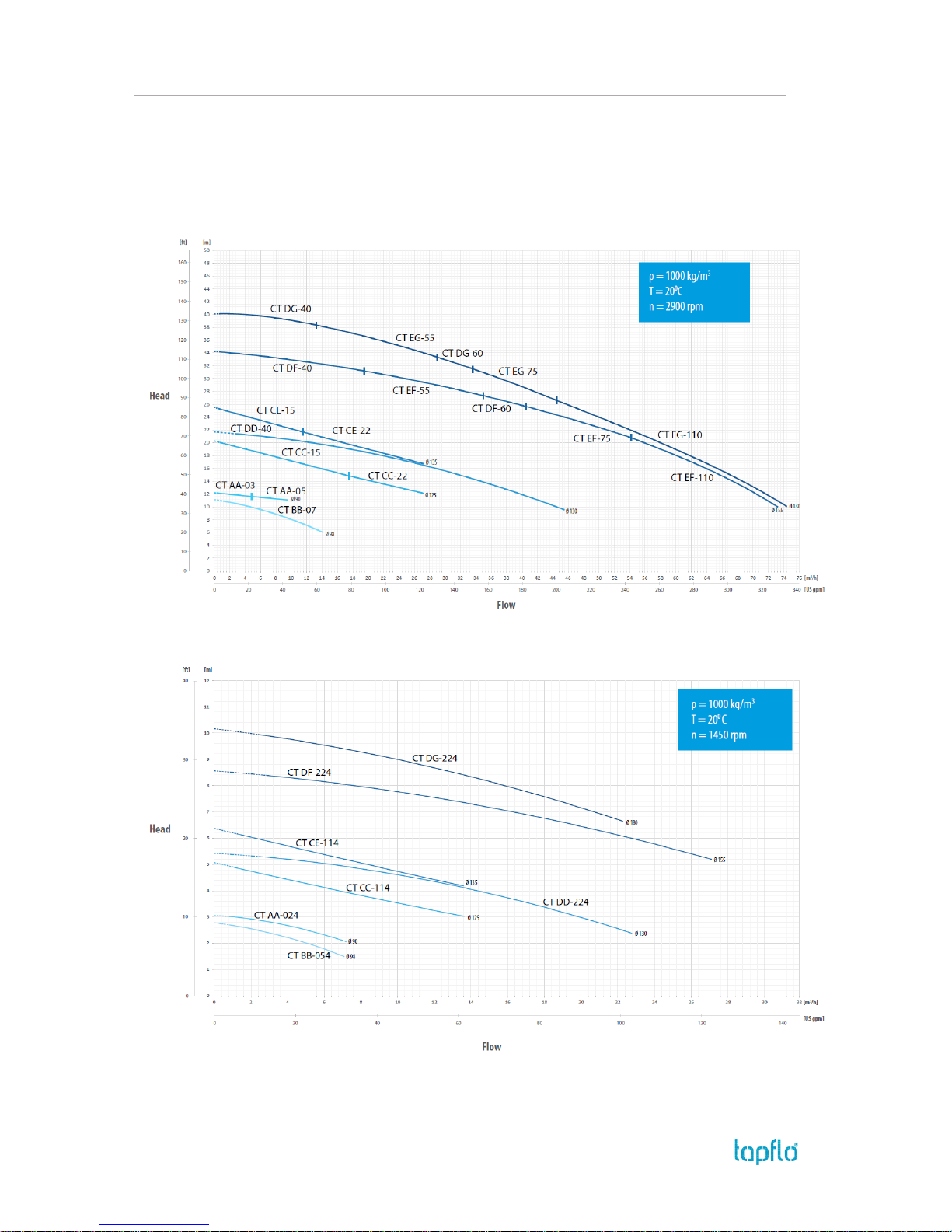
6. DATA
IOM manual CTI & CTH centrifugal pumps 45
6.7. Performance curves
The performance curves are based on water at 20°C.
Contact us for detailed curves
Speed 2900 rpm
Speed 1450 rpm
Page 46
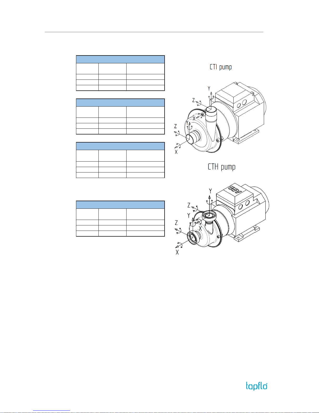
6. DATA
IOM manual CTI & CTH centrifugal pumps 46
6.8. Permitted loads on inlet and outlet
We recommend not to exceed the following loads and forces reacting on the inlet and
outlet.
*CTI / CTH
CT A
Direction
Load [N]
(inlet/outlet)
Moment of force
(inlet/outlet) [Nm]
X
70 6 Y
100 6 Z
70
6
CTI B
Direction
Load [N]
(inlet/outlet)
Moment of force
(inlet/outlet) [Nm]
X
80 8 Y
120
8
Z
80
8
CT C
Direction
Load [N]
(inlet/outlet)
Moment of force
(inlet/outlet) [Nm]
X
100
10
Y
150
10
Z
100
10
CT D / E
Direction
Load [N]
(inlet/outlet)
Moment of force
(inlet/outlet) [Nm]
X
100/120*
12
Y
170
12
Z
120
12
Page 47

7. WARRANTY
IOM manual CTI & CTH centrifugal pumps 47
7. WARRANTY
7.1. Returning parts
When returning parts to Tapflo please follow this procedure:
Consult Tapflo for shipping instructions.
Cleanse or neutralize and rinse the part/pump. Make sure the part/pump is
completely empty from liquid.
Pack the return articles carefully to prevent any damage during transportation.
Goods will not be accepted unless the above procedure has been complied with.
7.2. Warranty
Tapflo warrants products under conditions as stated below for a period of not more than 12
months from installation and not more than 24 months from date of manufacturing.
1. The following terms and conditions apply to the sale of machinery, components and
related services and products, of Tapflo (hereinafter “the products”).
2. Tapflo (the manufacturer) warrants that:
a. its products are free of defects in material, design and workmanship at the time of
original purchase;
b. its products will function in accordance with Tapflo operative manuals; Tapflo does
not guarantee that the product will meet the precise needs of the Customer except
for those purposes set out in any invitation to render documents or other documents
specifically made available to Tapflo before entering into this agreement;
c. high quality materials are used in the construction of the pumps and that machining
and assembly are carried out to the highest standards.
Except as expressly stated above, Tapflo makes no warranties, express or implied,
concerning the products, including all warranties of fitness for a particular purpose.
3. This warranty shall not be applicable in circumstances other than defects in material,
design and workmanship. In particular warranty shall not cover the following:
a. Periodic checks, maintenance, repair and replacement of parts due to normal wear
and tear (seals, O-rings, rubber items, bushings, etc..);
b. Damage to the product resulting from:
b.1. Tampering with, abuse or misuse, including but not limited to failure to use the
product for its normal purposes as stated at the time of purchase or in accordance
with Tapflo instructions for use and maintenance of the product, or the installation
or improper ventilation or use of the product in a manner inconsistent with the
technical or safety standard in force;
b.2. Repairs performed by non-skilled personnel or use of non-original Tapflo parts;
Page 48

7. WARRANTY
IOM manual CTI & CTH centrifugal pumps 48
b.3. Accidents or any cause beyond the control of Tapflo, including but not limited to
lightning, water, fire, earthquake and public disturbances etc.;
4. The warrantee shall cover the replacement or repairing of any parts, which is documented
faulty due to construction or assembling, with new or repaired parts free of charges delivered by Tapflo. Parts subjected to normal tear and wear shall not be covered by the
warranty. Tapflo shall decide as to whether the defective or faulty part shall be replaced
or repaired.
5. The warrantee of the products shall be valid for a period in accordance to the current law
from the date of delivery, under the condition that notice of the alleged defect to the
products or parts thereof be given to Tapflo in written within the mandatory term of 8
days from the discovery. Repair or replacement under the terms of this warranty shall not
give a right to an extension to or a new commencement of the period of warranty.
6. Repair or replacement under the terms of this warranty shall not give a right to an
extension to, or a new commencement of, the period of warranty. Repair or replacement
under the terms of this warranty may be fulfilled with functionally equivalent
reconditioned units. Tapflo qualified personnel shall be solely entitled to carry out repair
or replacement of faulty parts after careful examination of the pump. Replaced faulty parts
or components will become the property of Tapflo.
7. The products are built in accordance with standard CE normative and are tested (where
applicable) by Tapflo. Approval and tests by other control authority are for the customer’s
account. The products shall not be considered defective in materials, design or
workmanship if they need to be adapted, changed or adjusted to conform to national or
local technical or safety standards in force in any country other than that for which the
unit was originally designed and manufactured. This warranty shall not reimburse such
adaptations, changes or adjustments, or attempt to do so. whether properly performed or
not, nor any damage resulting from them, nor any adaptation change or adjustments to
upgrade the products from their normal purpose as described in the products operative
manual without the prior written consent of Tapflo.
8. Installation, including electric and other connections to utility mains according to Tapflo
drawings, is for the cost and responsibility of the customer, unless otherwise agreed in
writing.
9. Tapflo will not be liable on any claim, whether in contact, tort, or otherwise, for any
indirect, special, incidental or consequential damages caused to the customer or to third
parties, including loss of profits arising by any possible infringement of par. 3 above or by
the customer or third parties being in the impossibility of using the products.
Steady the above, Tapflo liability to the customer or third parties from any claim, whether in
contract, tort or otherwise, shall be limited to the total amount paid by the customer for the
product that caused the damages.
Page 49
7. WARRANTY
IOM manual CTI & CTH centrifugal pumps 49
7.3. Warranty form
Company:
Telephone:
Fax:
Address:
Country:
Contact Name:
E-mail:
Delivery Date:
Date of pump installation:
Pump type:
Serial No (see name plate):
Description of the fault:
The installation:
Liquid:
Temperature [°C]:
Viscosity [cPs]:
Spec grav. [kg/m3]:
pH-value:
Content of particles:
%, of max size [mm]:
Flow [l/min]:
Duty [h/day]:
No of starts per day:
Discharge head [mWC]:
Suction head / lift [m]:
Other:
Place for sketch of installation:
Page 50

7. WARRANTY
IOM manual CTI & CTH centrifugal pumps 50
TAPFLO AB
Sweden
Filaregatan 4 | S-442 34 Kungälv
Tel: +46 303 63390
Fax: +46 303 19916
E-mail addresses:
Commercial questions: [email protected]
Orders: [email protected]
Tech support: [email protected]
Tapflo products and services are available in 75 countries on 6 continents.
Tapflo is represented worldwide by own Tapflo Group Companies and carefully selected distributors assuring highest Tapflo service
quality for our customers’ convenience.
AUSTRALIA | AUSTRIA | AZERBAIJAN | BAHRAIN | BELARUS | BELGIUM | BOSNIA & HERZEGOVINA | BRAZIL | BULGARIA |
CANADA | CHILE | CHINA | COLOMBIA | CROATIA | CZECH REPUBLIC | DENMARK | ECUADOR | EGYPT | ESTONIA | FINLAND |
FRANCE | GREECE | GEORGIA | GERMANY | HONG-KONG | HUNGARY | ICELAND | INDIA | INDONESIA | IRAN | IRELAND | ISRAEL |
ITALY | JAPAN | JORDAN | KAZAKHSTAN | KUWAIT | LATVIA | LIBYA | LITHUANIA | MACEDONIA | MALAYSIA | MEXICO |
MONTENEGRO | MOROCCO | THE NETHERLANDS | NEW ZEALAND | NORWAY | POLAND | PORTUGAL | PHILIPPINES | QATAR |
ROMANIA | RUSSIA | SAUDI ARABIA | SERBIA | SINGAPORE | SLOVAKIA | SLOVENIA | SOUTH AFRICA | SOUTH KOREA | SPAIN |
SUDAN | SWEDEN | SWITZERLAND | SYRIA | TAIWAN | THAILAND | TURKEY | UKRAINE | UNITED ARAB EMIRATES |
UNITED KINGDOM | USA | UZBEKISTAN | VIETNAM
Tapflo Group Companies
Austria
Tapflo Austria
Tel: +43 732 27292910
[email protected]
Azerbaijan
Tapflo Azerbaijan LLC
Tel: +994 502660799
[email protected]
Baltic States
Tapflo Latvia
Tel: +371 67472205
[email protected]
Belarus
Tapflo Belarus
Tel: +375 17 3934609
[email protected]
Bulgaria
Tapflo EOOD
Tel: +359 (2) 974 18 54
[email protected]
Canada
Tapflo Canada
Tel: +1 514 813 5754
[email protected]
Croatia
Tapflo GmbH
Tel: +385 91 4884 666
[email protected]
Czech Republic
Tapflo s.r.o.
Tel: +420 513033924
[email protected]
China
Tapflo (Wuxi)
Tel: +86 510 8241 7602
[email protected]
Denmark
Tapflo Danmark
Tel: +45 36 454600
[email protected]
France
Tapflo France
Tel: +33 1 34 78 82 40
[email protected]
Georgia
Tapflo Georgia
Tel: +995 577 463010
[email protected]
India
Tapflo Fluid Handling India
Pvt Ltd
Tel: +91 20 65000215
Ireland
Tapflo Ireland Ltd
Tel: +353 1 2011911
[email protected]
Italy
Tapflo Italia
Tel: +39 0362307698
[email protected]
Japan
Tapflo Japan K.K.
Tel: +81-3-6240-3510
[email protected]
Kazakhstan
Tapflo Kazakstan
Tel: +7 727 3278347
[email protected]
Poland
Tapflo Sp. z o.o.
Tel: +48 58 530 42 00
[email protected]
Romania
S.C. Tapflo Rom. S.r.l.
Tel: +40 21 3451255
[email protected]
Russia
Tapflo Company
Tel: +7 495 232 18 28
[email protected]
Serbia
Tapflo d.o.o.
Tel: +381 21 44 58 08
[email protected]
Slovakia
Tapflo s.r.o.
Tel: +421 911 137 883
[email protected]
Slovenia
Tapflo GmbH
Tel: +386 68 613 474
[email protected]
Spain
Tapflo Iberica
Tel: +34 91 8093182
[email protected]
South Africa
Tapflo (Pty) Ltd
Tel: +27 31 701 5255
[email protected]
Turkey
Tapflo Makina Ltd
Tel: +90 216 467 33 11
[email protected]
Ukraine
TOB Tapflo
Tel: +380 44 222 68 44
[email protected]
Uzbekistan
Tapflo Uzbekistan
Tel.: +998 712370940
[email protected]
United Kingdom
Tapflo (UK) Ltd
Tel: +44 2380 252325
[email protected]
 Loading...