


OPERATION MANUAL
BAZOOKA® CONTINUOUS FLOW SYSTEM
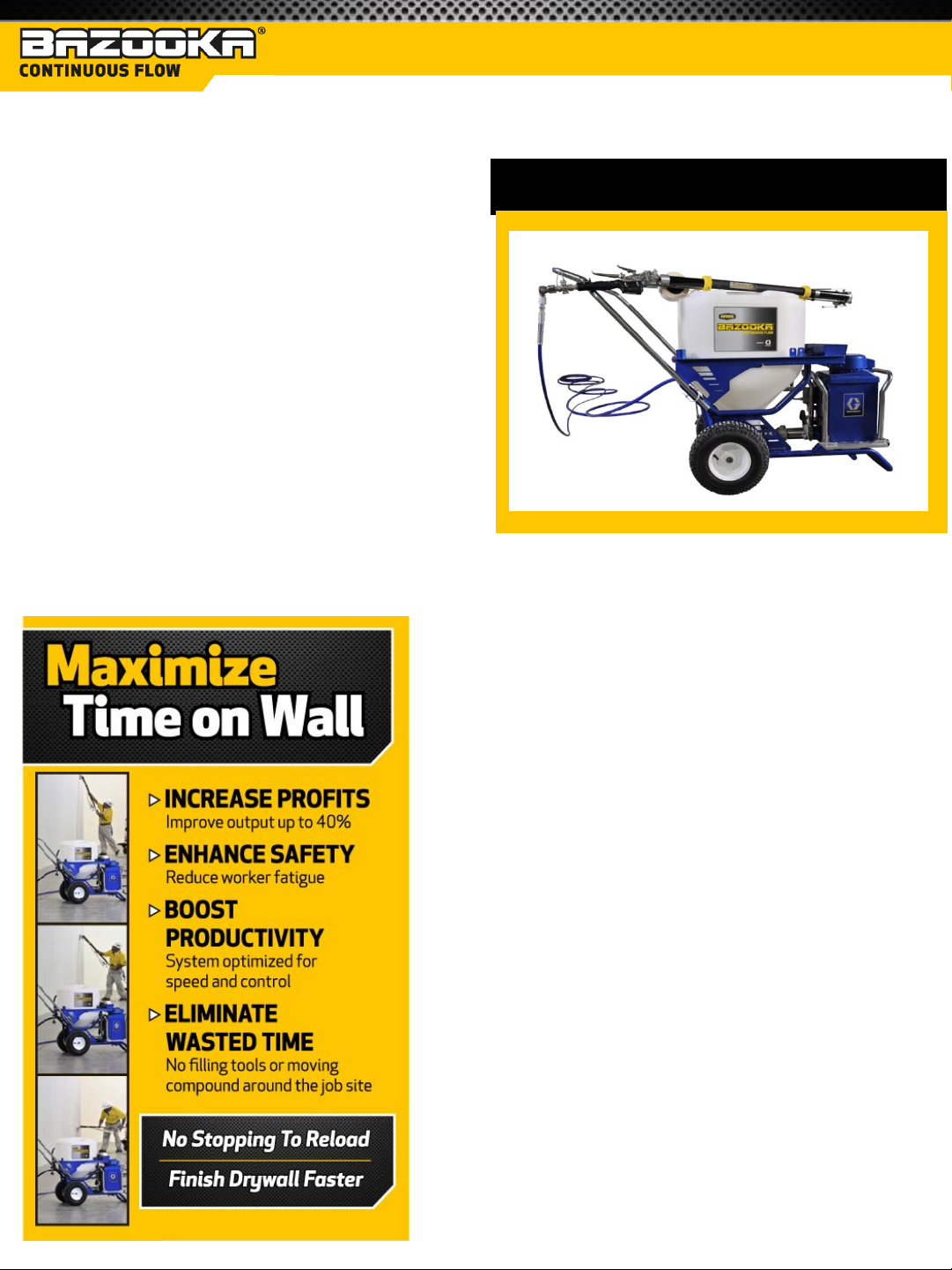
Finish drywall projects faster than ever
before when you keep your taping tool
continuously at work on the wall while the
Bazooka® system provides a continuous flow
of compound into your choice of tools.
Unlike traditional tapers that must be loaded
and reloaded using a hand pump, Bazooka®
Continuous Flow can work continuously
without having to stop and reload.
Best of all, current Bazooka® users can move
up to Bazooka® Continuous Flow with
minimal training.
Ames® Taping Tools - The World’s
A HIGH-VOLUME PRODUCTIVITY SYSTEM
Leading Provider of Drywall
Finishing Tools & Services
As the world’s leading provider of drywall
finishing tools and services, Ames® continues
to advance the needs of the industry through
product innovation, market development and
service delivery. Our Bazooka® taping and
finishing tools are the most advanced and
efficient tool systems used by the drywall
industry today.
Ames® also has the industry’s largest retail
operation, delivering drywall finishing tools
and services through a network of companyowned and franchise operations in the fastestgrowing residential and commercial
construction markets in the U.S. and Canada.
© 2011 AMES TAPING TOOLS
1

The following warnings are for the setup, use, grounding, maintenance and repair of this equipment. The exclamation
ELECTRIC SHOCK HAZARD
This equipment must be grounded. Improper grounding, setup, or usage of the system can cause electric shock.
• Turn off and disconnect power cord before servicing equipment.
• Use only grounded electrical outlets.
• Use only 3-wire extension cords.
• Ensure ground prongs are intact on power and extension cords.
• Do not expose to rain. Store indoors.
SKIN INJECTION HAZARD
High-pressure fluid from dispensing device, hose leaks or ruptured components will pierce skin. This may look
like just a cut, but it is a serious injury than can result in amputation. Get immediate surgical treatment.
• Engage trigger lock when not dispensing.
• Do not point dispensing device at anyone or at any part of the body.
• Do not put your hand over the fluid outlet.
• Do not stop or deflect leaks with your hand, body, glove, or rag.
• Follow the Pressure Relief Procedure when you stop dispensing and before cleaning, checking, or servicing
equipment.
• Tighten all fluid connections before operating the equipment.
• Check hoses and couplings daily. Replace worn or damaged parts immediately.
FIRE AND EXPLOSION HAZARD
Flammable fumes, such as solvent and paint fumes, in work area can ignite or explode. To help prevent fire and
explosion:
• Do not dispense flammable or combustible materials near an open flame or sources of ignition such as
cigarettes, motors, and electrical equipment.
• Material or solvent flowing through the equipment is able to result in static electricity. Static electricity
creates a risk of fire or explosion in the presence of material or solvent fumes. All parts of the system,
including the pump, hose assembly, dispenser, and objects in and around the work area shall be properly
grounded to protect against static discharge and sparks. Use Graco® conductive or grounded high-pressure
airless material hoses.
• Verify that all containers and collection systems are grounded to prevent static discharge.
• Connect to a grounded outlet and use grounded extension cords. Do not use a 3-to-2 adapter.
• Do not use a material or a solvent containing halogenated hydrocarbons.
• Keep work area well ventilated. Keep a good supply of fresh air moving through the area. Keep pump
assembly in a well ventilated area.
• Do not smoke in the work area.
• Do not operate light switches, engines, or similar spark producing products in the work area.
• Keep area clean and free of material or solvent containers, rags, and other flammable materials.
• Know the contents of the materials and solvents being dispensed. Read all Material Safety Data Sheets
(MSDS) and container labels provided with the materials and solvents. Follow the materials and solvents
manufacturer’s safety instructions.
• Fire extinguisher equipment shall be present and working.
• Drywall feed and pump generates sparks. When flammable liquid is used in or near the drywall feed pump
or for flushing or cleaning, keep unit at least 20 feet (6 m) away from explosive vapors.
point symbol alters you to a general warning and the hazard symbols refer to procedure-specific risks. When these
symbols appear in the body of this manual, refer back to these Warnings. Product-specific hazard symbols and warnings
not covered in this section may appear throughout the body of this manual where applicable.
© 2011 AMES TAPING TOOLS
2

MOVING PARTS HAZARD
Moving parts can pinch, cut or amputate fingers and other body parts.
• Keep clear of moving parts.
• Do not operate equipment with protective guards and covers removed.
• Pressurized equipment can start without warning. Before checking, moving, or servicing equipment, follow
the Pressure Relief Procedure and disconnect all power sources.
EQUIPMENT MISUSE HAZARD
Misuse can cause death or serious injury.
• Always wear appropriate gloves, eye protection, and a respirator or mask when dispensing.
• Do not operate or dispense near children. Keep children away from equipment at all times.
• Do not overreach or stand on an unstable support. Keep effective footing and balance at all times.
• Stay alert and watch what you are doing.
• Do not leave the unit energized or under pressure while unattended. When the unit is not in use, turn off
the unit and follow the Pressure Relief Procedure for turning off the unit.
• Do not operate the unit when fatigued or under the influence of drugs or alcohol.
• Do not kink or over-bend the hose.
• Do not expose the hose to temperatures or to pressures in excess of those specified by Graco®.
• Do not use the hose as a strength member to pull or lift the equipment.
PRESSURIZED ALUMINUM PARTS HAZARD
Use of fluids that are incompatible with aluminum in pressurized equipment can cause serious chemical reaction
and equipment rupture. Failure to follow this warning can result in death, serious injury, or property damage.
• Do not use 1,1,1 – trichloroethane, methylene chloride, other halogenated hydrocarbon solvents or fluids
containing such solvents.
• Many other fluids may contain chemicals that can react with aluminum. Contact your material supplier for
compatibility.
PERSONAL PROTECTIVE EQUIPMENT
You must wear appropriate protective equipment when operating, servicing, or when in the operating area of
the equipment to help protect you from serious injury, including eye injury, hearing loss, inhalation of toxic
fumes, and burns. This equipment includes, but is not limited to:
• Protective eyewear and hearing protection.
• Respirators, protective clothing, and gloves as recommended by the fluid and solvent manufacturer.
© 2011 AMES TAPING TOOLS
3

COMPONENT IDENTIFICATION
© 2011 AMES TAPING TOOLS
4

BAZOOKA® PAGE
• General 6-8
• Operation 9-11
• Maintenance 11-12
FLAT FINISHER BOX PAGE
USING FINISHING TOOLS
• General 13-15
• Operation 16
• Maintenance 17
CORNER TOOL HANDLE PAGE
• General 18-19
• Operation 19-20
• Maintenance 20
© 2011 AMES TAPING TOOLS
5
BAZOOKA®
The taping process using the Bazooka® Continuous Flow Taper.
There are three important facts you should remember about the Bazooka® Continuous Flow Taper:
• Current automatic taper users can move up to Bazooka® Continuous Flow with minimal training – the tools are
almost identical!
• It simultaneously applies tape and joint compound to any wall joint and will cut the tape to the desired length.
• Unlike traditional tapers that must be loaded and reloaded using a hand pump, Bazooka® Continuous Flow can
work continuously without having to stop and reload.
GENERAL:
1. The Bazooka® Continuous Flow Taper is designed to work with tape that is 2-1/16 to 2-1/8” wide. Wider tape will
bind and narrower tape may have a tendency to jam.
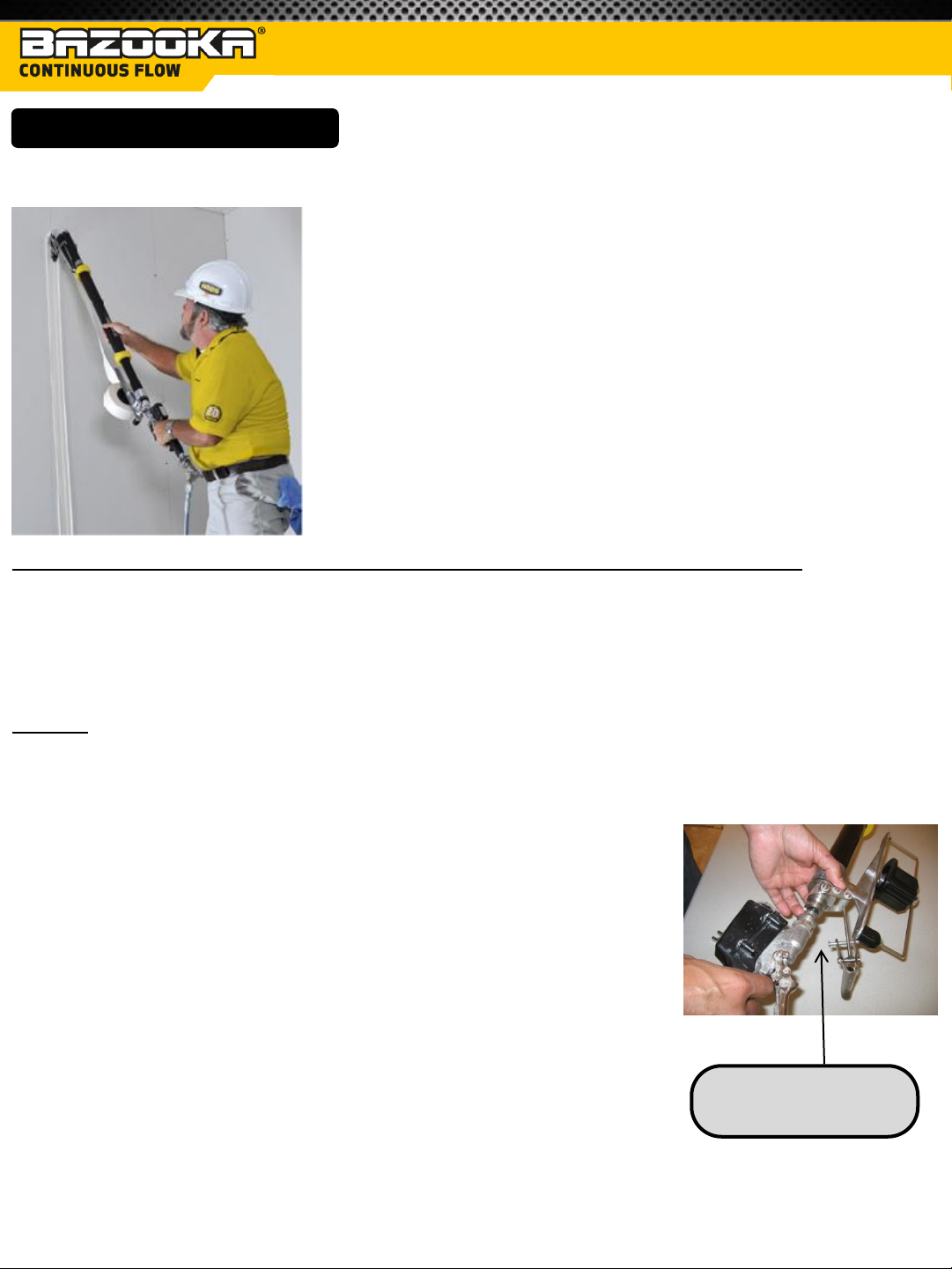
2. The taper is used in conjunction with the inline mechanical valve.
3. Connect them by installing the quick disconnect pilot fitting into the
connection on the end of the taper.
Attach taper to inline
mechanical valve
6
© 2011 AMES TAPING TOOLS

4. Align the valve so that the trigger lines up with the tape spool.
Secure by tightening the clamp nut.
5. The creaser trigger is attached to the valve using the clevis pin.
6. The range of the creaser trigger may be adjusted by threading the
nut in or out.
7. The hose can now be connected to the open end of the valve, similar
to the way that the valve was attached to the taper.
BAZOOKA® (cont’d)
8. Install a roll of drywall tape onto the spool mount of the taper so
that it will unwind clockwise as you look at the roll.
9. Secure the roll by looping the keeper into the slot on the spool post
and inserting the anchor into the receptacle on the spool mount.
10. Feed the tape through the tape guide with the back side of the tape
facing away from you so that the curl of the tape will go over the
main wheel of the taper.
11. Advance a tab of tape over the main wheel of the taper.
Tape curls over
the taper wheel
Tape guide
7
© 2011 AMES TAPING TOOLS

BAZOOKA® (cont’d)
12. The taper is operated by placing one hand on the inline mechanical
valve, controlling the compound flow, and the other hand on the
taper control tube, controlling tape advancing and cutting.
13. Normally, the control tube is held at the top most end of its stroke
during taper operation.
14. The spring loaded creaser wheel may also be retracted temporarily
by operating the creaser trigger with the hand on the inline
mechanical valve.
15. If the lever is used, it is released once the taper is positioned so that
the valve lever can be operated.
16. During normal operation, the creaser is extended and always
applying some amount of pressure to seat the tape onto the wall.
17. The flow of material from the pump to the taper is actuated by fully
squeezing the valve lever.
Start compound flow
by fully squeezing the
valve lever
18. Joint compound will flow through the hose, into the taper and onto
the exposed tab of tape.
19. You are now ready to tape your first joint. An additional tape
advance may be helpful for starting some joints, especially ceiling
and ceiling angles.
20. The operator must ensure the proper amount of compound is
dispensed onto the tape by matching the speed of the taper head
with the flow of material from the pump.
21. For best results, the operator will need to ensure that the head of
the tool travels at a consistent speed over the full length of the
joint or excess and/or insufficient amounts of compound will result.
22. Speed can be adjusted by pressing the adjustment buttons on the
inline mechanical valve.
23. Speed cannot be increased above that set by the control knob on the
pump, but can be adjusted up and down below that setting.
Flow rate adjustments can
be made using the “+” and
“-” buttons on the inline
valve controller
8
© 2011 AMES TAPING TOOLS

BAZOOKA® (cont’d)
TAPER OPERATION:
1. Generally you will start by taping butt joints first, followed by flat joints and finally inside angle joints.
2. You will need to position the end of the exposed tab of tape at the beginning of the joint to be taped. This may
be done by advancing the tape one time and manipulating the creaser wheel to retract it (either with pressure
against the adjoining wall or floor, or by using the creaser trigger).
3. Alternately, the tape can be advanced twice so that it extends over the creaser wheel. Whichever method you
use, apply a bit of joint compound to this exposed tab of tape by giving the valve lever a quick squeeze.
TRAINING NOTE: With the Bazooka® Continuous Flow Taper there is no drag on the tape (because the tool does
not have a cable and piston). Therefore you will rarely need to produce a long tab of tape to start a flat or angle
joint.
VERTICAL JOINTS:
1. To tape a vertical joint, place the tab of tape at the bottom of the joint you wish to tape, holding the taper about
20 degrees above horizontal.
2. Maintain contact between the main wheel of the taper and the wall and fully squeeze the valve lever when you
begin moving the head of the taper along the joint.
3. Maintain an even speed for the head of the taper, realizing that the natural swing of your arms will result in an
increase in speed as you approach waist level.
4. Lead with the head of the taper as soon as is practical to make tracking easier.
5. When the head of the taper is about 3” from the end of the joint, release the valve lever as you stop moving the
taper.
6. Holding the taper stationary with your valve hand, cut the tape by pulling the control tube fully toward you in a
smooth motion and then roll the remaining tape onto the end of the joint.
7. Advance the next tab of tape by pushing the control tube fully away from you in a smooth motion and you are
ready to start the next joint.
TRAINING NOTE: It is very important to come to a complete STOP before cutting the tape.
9
© 2011 AMES TAPING TOOLS

BAZOOKA® (cont’d)
HORIZONTAL JOINTS:
1. To tape horizontal joints, place the tab of tape at the beginning of the joint to be taped. Squeeze the valve lever
fully as you begin to move the head of the taper along the joint.
2. Lead with the head of the taper as soon as is practical to make tracking easier.
3. When the head of the taper is about 2-1/2” from the end of the joint, release the valve lever as you stop moving
the taper.
4. Holding the taper stationary with your valve hand, cut the tape by pulling the control tube fully toward you in a
smooth motion and then roll the remaining tape onto the end of the joint.
5. Advance the next tab of tape by pushing the control tube fully away from you in a smooth motion and you are
ready to start the next joint.
TRAINING NOTE: When holding the taper it’s always best to have the control tube in the forward position.
CEILING JOINTS:
1. Run the taper on two wheels for the first 4-6 inches of a ceiling joint. Then tilt the taper at a 45 degree angle so
that only one of the drive wheels is contacting the ceiling , engage the creaser wheel, and run the remainder of
the joint.
2. Walk towards the other end of the joint, leading with the head of the tool.
3. Stop and cut at about 2-1/2” from the end of the joint, rolling out the tape on the remainder of the joint when
done.
TRAINING NOTE: Tilting the body of the taper toward you slightly is an essential step. This will help prevent
material from dripping on the floor (and on you!).
INSIDE ANGLES:
1. Position the tab of tape at the beginning of the angle joint, holding the body of the taper in such a way as to
bisect the angle as much as is possible to center the tape and the main wheel in the joint.
2. The creaser wheel will automatically apply an appropriate amount of pressure to the tape to seat the tape in the
joint.
3. Start compound flow as you move the taper along the joint, stopping and cutting about 2-1/2” from the end of
the joint.
10
© 2011 AMES TAPING TOOLS

BAZOOKA® (cont’d)
INSIDE ANGLES (cont’d):
4. For best operation, avoid “twisting” the taper as you track the joint and lead with the head of the taper as soon as
is practical. This will minimize “creeping” of the tape along the joint.
MAINTENANCE:
1. This tool must be thoroughly washed after each use. Flush the compound from the tool with water, either with
the pump or with a water hose and cleaning adapter.
2. Remove the cover plate and thoroughly clean any compound remaining in the head, in the tape guide and in the
cutter area. External material can be sprayed off with a hose or removed with a cleaning brush.
3. After cleaning, lightly lubricate all moving parts with Ames® Bazooka® Oil.
4. The creaser trigger can be plugged into the butt end of the tool for storage.
5. A few parts on the taper do exhibit wear with use and need to be replaced periodically.
CUTTER BLADE REPLACEMENT:
1. The cutter blade is sharp and should always be handled with pliers.
2. Unhook the cutter chain from its mounting post and carefully pull the cutter chain assembly out of the cutter
channel until the blade is exposed.
3. Noting how the current blade is installed in the cutter block, remove
it by loosening the clamp screw.
4. Install the new blade so that it seats fully under the clamp and
against the clamp screw. Securely tighten the clamp screw.
5. Ensure that the head of the clamp screw is facing toward the main
wheel and pull the blade assembly back into the cutter channel.
6. Re-install the cutter spring on its mounting post, ensuring the chain isn’t twisted as you do so.
7. Gently pull down on the control tube to ensure that the cutter blade is moving smoothly in the cutter channel
before resuming taping operations.
11
© 2011 AMES TAPING TOOLS

BAZOOKA® (cont’d)
GOOSER NEEDLE REPLACEMENT:
1. The gooser needle is sharp and should always be handled with pliers.
2. While holding the pin that extends out of the needle holder, loosen
the clamp screw and remove the existing gooser needle with a pair
of pliers.
3. Insert some tape in the tape guide and then install the new needle
using a pair of pliers.
4. Gently press the needle into the tape so that the point slightly protrudes through the other side of the tape and
tighten the clamping screw. (Caution: You want the needle to grab the tape, however you do not want the
needle to pass through the tape) .
5. When installed properly, the needle should securely drive the tape forward when advancing, but fully release
from the paper when the gooser is at the top of its stroke and then skim over the top of the paper as it returns to
the bottom of its stroke.
12
© 2011 AMES TAPING TOOLS

FLAT FINISHER BOX
The finishing process using the Bazooka® Continuous Flow Flat Finisher Box and Handle.
There are three important facts you should remember about the Bazooka® Continuous Flow Flat Finisher Box and
Handle:
• The learning curve is minimized because the brake and box operation is almost identical to a traditional Ames®
box and handle.
• The teardrop shape of the handle makes it very comfortable and easy to use.
• Unlike traditional boxes that must be loaded and reloaded using a hand pump, Bazooka® Continuous Flow can
work continuously without having to stop and reload.
GENERAL:
1. The continuous flow flat finisher boxes and handles are used to apply joint compound over previously taped
joints. They are easy to operate and produce uniform results every time.
2. The boxes come in 3 widths: 7”, 10” and 12”. Generally the next larger sized box is used over the previously
used size until the desired level of finish is obtained. These are the same sizes as the original Ames® boxes!
3. These special boxes must be used with the handles and box slide controller designed for them. The handles come
in 4 lengths, 34”, 42”, 54” and 72”. These are the same sizes as the original Ames® handles!
4. The handles have an ergonomic shape to improve performance and comfort.
5. A special box slide controller is attached over each handle to control the flow of material from the pump into the
finisher box.
6. Using the upper hand, the operator simply presses a trigger on the transmitter box to turn the pump on and off
as desired.
13
© 2011 AMES TAPING TOOLS

FLAT FINISHER BOX (cont’d)
7. After selecting the proper width box and length of handle for the job,
the operator connects them by threading the box studs into the
wingnuts on the handle connector plate.
8. The wingnuts should be tightened snuggly by hand, but no tools need
to be used to provide a secure connection.
No tools needed to
tighten wingnuts
9. The hose is then connected by inserting the quick disconnect pilot
fitting of the hose into the grip end of the handle.
10. Secure by hand tightening the clamp nut.
Quick disconnect
pilot fitting
14
© 2011 AMES TAPING TOOLS

11. The box slide controller is then wrapped around the handle with the
extended portion of the transmitter closest to the brake lever grip.
12. The box slide controller should securely snap in place over the shape
of the handle and can either be locked into place or allowed to slide
freely by adjusting the locking nut on the top side.
The box slide controller brake
allows the controller to be
positioned on the handle
13. The box must be at least partially filled with compound before it will
finish properly.
14. Hold the handle so that the material outlet is visible and facing
upward and depress one of the box slide controller triggers to start
the flow of mud.
FLAT FINISHER BOX (cont’d)
15. Joint compound must flow through the hose and into and through
the handle, so the box may not begin to fill immediately.
16. Fill the box so that it is 50-70% full of compound before beginning to
use.
17. Operation of the brake system to orient and lock the box in place are
just as with other existing ATF type handles.
18. Similarly, the crown is controlled with the dial as on existing ATF type
boxes.
Same crown adjustment
dial as on traditional
Ames® box
15
© 2011 AMES TAPING TOOLS

FLAT FINISHER BOX (cont’d)
BOX OPERATION:
1. The Ames® Continuous Flow Flat Finishers can be used in a variety of ways. It’s possible to use these boxes very
much like traditional ATF flat finishers by using the pump between joints to keep the boxes supplied with
compound.
2. It’s also possible to use the pump only when the boxes are on the wall to actually help push the material out of
the box. Or any combination of the above may be used as well.
BEGIN FLATS:
1. Using the pump to maintain the mud supply in the box between joints is the easiest way to learn how to use the
tools for an operator that is proficient with current flat finisher boxes.
2. After finishing a joint with the box, the operator presses one of the triggers on the box slide controller to refill the
box with the appropriate amount of compound. The operator then positions to finish the next joint.
3. Using the pump while the box is on the wall takes advantage of the pump to help push the material out of the
box, but takes a bit more time to learn:
a. The operator must position the box slide controller so that he can actuate the trigger as desired while
moving the tool along the joint.
b. The speed of movement must also be coordinated with the speed of the pump so that the box doesn’t
run empty or fill up.
c. It is important that the finisher box be run about ½ full when operating the system in this way or finish
quality can suffer.
d. Also, the trigger should be released 6-12” from the end of the joint to allow for the gradual stoppage of
compound flow through the hose.
4. Thick edges on one side or both and/or streaks pulled in the direction of finish are indications that either box
speed should be increased and/or pump speed should be decreased.
5. Excess material on the bottom plate of the box can be indicative of a number of things: pushing harder than is
required, using compound thinner than optimum, holding the trigger too long, running the box too full.
16
© 2011 AMES TAPING TOOLS

FLAT FINISHER BOX (cont’d)
MAINTENANCE:
1. This tool must be thoroughly washed after each use. Flush the compound from the tool with water, either with
the pump or with a water hose and cleaning adapter.
2. External material can be sprayed off with a hose or removed with a cleaning brush.
3. After cleaning, lightly lubricate all moving parts with Ames® Bazooka® Oil.
BOX BLADE REPLACEMENT:
1. To remove the used blade, place the tip of a screwdriver against one end of the blade and tap the end of the
screwdriver with the palm of your hand.
2. If this does not pop the end of the blade out, force it out by tightening the adjuster screw on that end.
3. Back the screw out to where it was and tap the end of the blade again.
4. Use one end of the used blade to help clean any mud residue left in the blade holder slot.
5. Slightly bend the end of the new blade approximately 2” from each end. This will help to secure the blade in the
holder during use.
6. Starting at one end, press the blade fully into the blade holder slot. Work your way to the other end of the blade
until it’s fully installed.
7. Turn the adjuster screws so that the end of each blade is just slightly above the surface of the skid.
17
© 2011 AMES TAPING TOOLS

CORNER TOOL HANDLE
The finishing process using the Bazooka® Continuous Flow Corner Tool Handle.
There are three important facts you should remember about the Bazooka® Continuous Flow Corner Tool Handle:
• It eliminates lap marks because you only have to move along the joint in one direction.
• It uses heaver joint compound, therefore there is less shrinkage and better coverage over the tape.
• Unlike traditional corner tools that must be loaded and reloaded using a hand pump, Bazooka® Continuous Flow
can work continuously without having to stop and reload.
GENERAL:
1. The continuous flow corner tool handle is used to finish inside corners or to apply joint compound to outside
corners as part of the application of corner bead.
2. It works with existing Ames® corner tools.
3. The handle is used in conjunction with the inline mechanical valve.
4. Connect them by installing the quick disconnect pilot fitting into the
connection on the end of the handle.
© 2011 AMES TAPING TOOLS
18

CORNER TOOL HANDLE (cont’d)
5. Secure by tightening the clamping nut.
6. The hose can now be connected to the open end of the valve, similar to the way that the valve was attached to
the handle.
7. The corner tool can now be installed over the end of the handle outlet ball.
8. The flow of material from the pump through the handle is actuated by fully squeezing the valve lever. Compound
will flow through the hose, through the handle out of the ball outlet.
9. The operator must ensure the proper amount of joint compound is dispensed by matching the speed of the
corner tool to the flow of material from the pump.
10. If compound is overflowing the corner tool, speed of movement should be increased and/or the pump speed
should be decreased.
11. If there is not enough material, then speed of movement should be decreased and/or the pump speed should be
increased.
12. Speed can be adjusted by pressing the adjustment buttons on the inline mechanical valve.
13. Speed cannot be increased above that set by the control knob on the pump, but can be adjusted up and down
below that setting.
14. Because the pump is supplying the compound for this application, it’s possible to use slightly thicker material for
this application compared to that used with a corner applicator box.
CORNER TOOL OPERATION:
1. Place the corner tool at one end of the joint to be finished.
2. Best results are obtained when the handle is held so that it bisects the angle to be finished and only as much
pressure is applied to fully seat the tool in the angle.
3. Orient the handle so that the neck of the outlet will not bind on the tool being used as you move it along the
angle to be finished.
© 2011 AMES TAPING TOOLS
19

CORNER TOOL HANDLE (cont’d)
BEGIN ANGLES:
1. Fully squeeze the valve lever to start the flow of compound and
move the tool toward the other end of the joint.
2. Release the valve lever to stop the flow of compound about 3-6”
from the end of the joint.
3. Repeat for the next joint to be finished.
TRAINING NOTE: For horizontal angles, you can run the joint around the entire room in the same direction. For
vertical angles, you should start at the floor and run the joint in one sweep to the very top.
MAINTENANCE:
1. This tool must be thoroughly washed after each use. Flush the compound from the tool with water, either with
the pump or with a water hose and cleaning adapter.
2. External material can be sprayed off with a hose or removed with a cleaning brush.
© 2011 AMES TAPING TOOLS
20

TROUBLESHOOTING TIPS
UNIT AND PUMP*
1. Low mud flow
• Check amp switch. It is always better when possible to run the pump on 20 amp rather than 15.
• You should not use less than 12G cord and no longer than 200’.
• Compound consistency is important; the thicker the material the slower the compound flow.
• Make sure pump has been properly primed (always when filling the hopper for the first time, put a small
amount of joint compound under the filter screen to start suction).
• Make sure filter screen is not clogged.
• Check pump speed control. Remember the range that you set the speed control at the pump will be the range
that you will have at the valve transmitter.
• Using lightweight joint compound may slow down material flow.
2. Blowing breakers
• Move amp switch to 15 amp position or move cord to a different outlet.
3. Transmitters not working
• Check batteries and battery connections.
• Make sure that the pump has learned that particular transmitter (transmitters must be learned within 10’ of
the pump).
• Do not submerge transmitters in water.
MAINTENANCE*
1. Pump remaining compound into a bucket via the priming hose.
2. Add clean water to hopper and wipe down inside of hopper with brush or sponge.
3. Turn directional valve to hose position and pump compound out of hose into bucket until you see water flowing.
4. Pump remaining dirty water out via the priming hose then run more clean water through the system following
the above procedure in steps 1 - 3.
5. Pump remaining water out then add and leave a small amount of Graco® Pump Armor into the bottom of the
hopper.
6. Lubricate Z-swivel with Ames® Bazooka® Oil.
*See Graco® Drywall Feed Pump Operations Manual for additional troubleshooting and maintenance tips.
© 2011 AMES TAPING TOOLS
21

TROUBLESHOOTING TIPS (cont’d)
TAPER
1. Flat tape pulls away from end of joint
• Operator failed to maintain consistent pressure on the drive wheel.
• Operator is pulling tape along, as opposed to rolling the tape out (this system reduces this problem).
2. Angle tape pulls out of corner
• Operator failed to maintain consistent pressure on the drive wheel.
• Operator is pulling tape along, as opposed to rolling the tape out (this system reduces this problem).
3. Joint compound drips when taping ceiling flats
• Run on two wheels for the first 4-6 inches, then run the taper on one wheel at a 45 degree angle with the
creaser wheel.
• Compound consistency is too thin.
4. Tape falls off
• Operator did not place enough pressure on the drive wheel.
• Compound consistency is too thin.
5. Tape will not advance
• Tape is not properly threaded (crinkles, creases and/or jams).
• Defective tape advancement assembly - check for adjustment on the gooser needle.
• Obstruction in the tape slide (metal and/or paper).
6. Taper will not run smooth on ceiling angles
• Tool needs to track on a straight line - should bisect the angle.
• If tool is turned slightly clockwise or counterclockwise, chatter will occur.
• Back-end of tool should be at a 45 degree angle – should not be held too high or low.
7. Blanks – no joint compound under tape
• The operator must ensure the proper amount of compound is dispensed onto the tape by matching the speed
of the taper head with the flow of material from the pump.
• Hopper is out of joint compound.
8. Excess or insufficient joint compound under tape
• For best results, the operator will need to ensure that the head of the tool travels at a consistent speed over
the full length of the joint or excess and/or insufficient amounts of material will result.
© 2011 AMES TAPING TOOLS
22

TROUBLESHOOTING TIPS (cont’d)
FLAT BOX AND HANDLE
1. Box leaves edges
• Box blade is not adjusted properly. Adjust blade.
• Blade is worn out and no adjustment is left. Replace with new box blade.
• Box skids are worn out. Replace skids and adjust to blade.
2. Air bubbles or “Fish Eyes” on the finished joint
• Crown not adjusted correctly. Adjust crown height setting for application.
• Too much water added to joint compound. Add less water when mixing joint compound.
• Pressure plate springs have been removed. Install pressure plate springs (2).
• Poor or improper drywall installation. Feather or wipe down joints as necessary.
3. Insufficient tape coverage
• Crown not adjusted correctly. Adjust crown height .
• Tape not completely dry. Allow tape to dry completely.
• Tape not wiped down properly. Ensure that tape is wiped down properly within recessed joints and butt joints.
• Inconsistent pressure on tool. Correct with natural operator body motion and consistent pressure on the tool.
• Inconsistent pressure along the joint. Correct with body positioning and how the operator leans into the tool as
it runs along the joint.
• Difficulty filling the tops of stand up joints. Slow your speed at the very top of the joint and allow the pump to
assist you.
4. Excess joint compound at beginning of joint and intersections
• Compound consistency is too thin. Mix joint compound with less water and to adequate consistency for
application.
• Improper brake release with box handle. Release brake after movement of flat box on joint.
5. Box is hard to push
• Compound consistency is too thick. Add water and mix joint compound to adequate consistency for
application.
• Pressure plate wiper installed improperly or not lubricated. Check to ensure that the wiper is installed properly
and lubricate with Ames® Bazooka® Oil for easy movement.
6. Joint compound leaks out of flat box
• Compound is mixed too thin. Mix joint compound with less water.
7. Box wheels are leaving “black tracks”
• Wheels need lubrication. Apply Ames® Bazooka® Oil.
8. There are “scratches” or “debris” in the joint compound
• Blade needs to be cleaned. Remove debris from blade surface and blade holder.
© 2011 AMES TAPING TOOLS
23

TROUBLESHOOTING TIPS (cont’d)
CORNER TOOL HANDLE
1. Too much joint compound on one side
• Tool needs to be centered in the angle to allow consistent pressure on each side.
• Center the tool to the angle - not your body.
• Corner finisher is worn - exchange for fresh tool at your local Ames® store location.
2. Tool drags and leaves marks
• Debris in and around the corner finisher.
• The corner finisher bisects the angle not your body (also known as tool operational positioning).
• The bend on the handle helps you apply pressure to the center of the corner finisher, when your body is not
positioned to do so.
3. Excess or insufficient joint compound flow
• The operator must ensure the proper amount of joint compound is dispensed by matching the speed of the
corner tool to the flow of material from the pump.
© 2011 AMES TAPING TOOLS
24

TECHNICAL DATA
© 2011 AMES TAPING TOOLS
25

NOTES
NOTES
© 2011 AMES TAPING TOOLS
26

AMES STANDARD WARRANTY
LIMITED ONE (1) YEAR WARRANTY
Effective October 1, 2010
Ames® Taping Tools (SELLER) warrants that all Ames® tools will be free from defects in material or workmanship for
a period of one (1) year from date of purchase. SELLER'S SOLE OBLIGATION under this Warranty and, to the extent
permitted by law, any warranty or condition implied by law shall be the repair or replacement of parts, without
charge, which are defective in material or workmanship. At the SELLER'S sole discretion, a replacement tool may be
supplied if original tool is found to be unrepairable, in which case, the original warranty term will remain in effect for
the replacement tool. This warranty is void if the tool has been damaged by accident, in shipment, misuse, neglect,
improper service, installation of non-Ames® parts, unauthorized modifications or repaired by persons other than
Authorized Service Centers. To make a claim under this warranty, you must return the complete tool, transportation
prepaid, to Ames® Service Center or an Authorized Warranty Repair Center.
CUSTOMER'S RESPONSIBILITY under this Warranty begins on the date of customer purchase. Warranty is not
transferable. For your convenience, keep your dated bill of sale as evidence of the purchase date. You are required to
present this bill of sale to the service center to obtain warranty repair. Please include a brief statement indicating the
nature of the problem. For warranty service information or a complete list of Warranty Service Centers contact the
place of purchase, or contact our Customer Service Department for assistance:
Ames® Taping Tools
Customer Service Department
800-241-2771
IN NO EVENT SHALL AMES TAPING TOOLS BE LIABLE FOR ANY INCIDENTAL OR CONSEQUENTIAL DAMAGE, DELAY
IN RENDERING OF SERVICE, OR LOSS OF USE DURING THE PERIOD IN WHICH THE TOOL IS AT THE REPAIR CENTER
OR OTHERWISE, WAITING REPAIR OR PARTS. This warranty gives you special legal rights and you may also have
other rights, which vary from state to state. Some states do not allow exclusion or limitations of incidental or
consequential damages or limitations on how long any implied warranty may last, so the above exclusions and
limitations may not apply to you.
© 2011 AMES TAPING TOOLS
27

 Loading...