

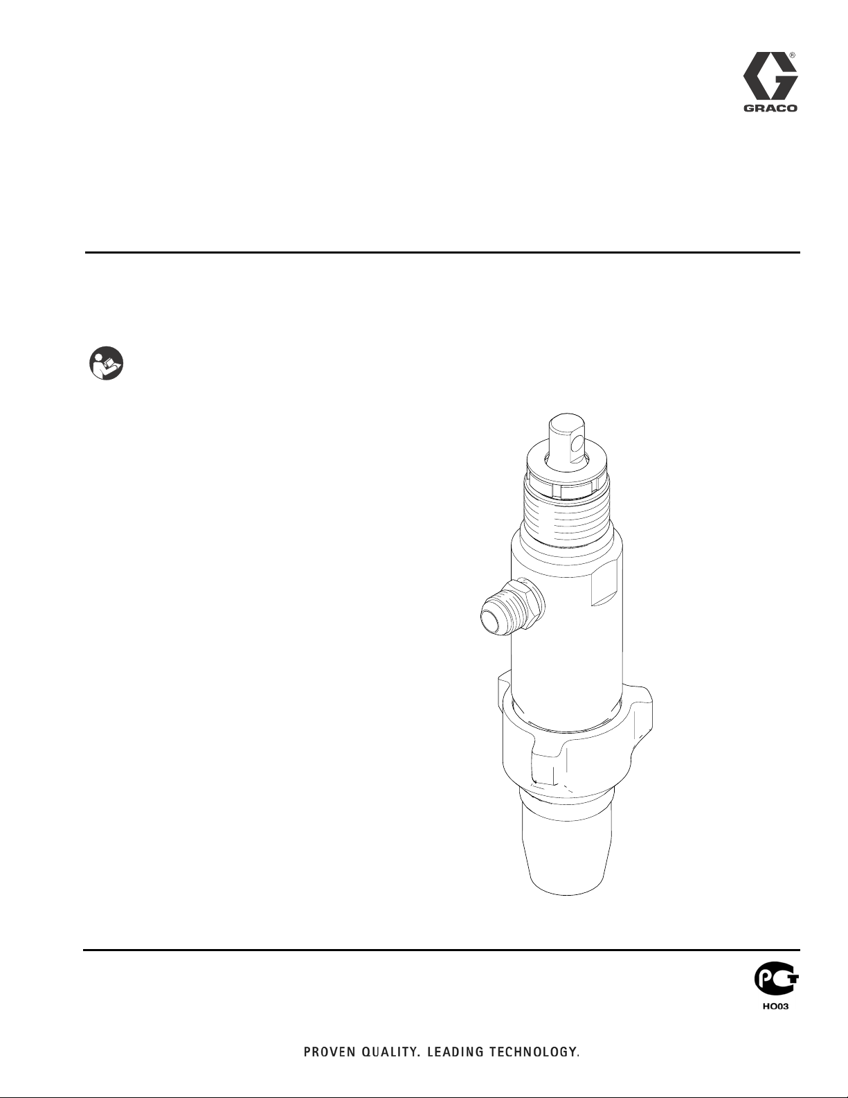
Repair
Pump for Drywall Feed Pump System
- For water-based materials only -
- Not for use in explosive atmospheres -
- Not for use with quick-set materials -
READ ALL WARNINGS AND INSTRUCTIONS
Read all warnings and instructions in this manual.
Save these instructions.
Maximum Working Pressure 2500 psi (17.2 MPa, 172 bar)
Model 24E957
3A0912A
ENG
ti15866a
Warning
Warning
The following warnings are for the setup, use, grounding, maintenance, and repair of this equipment. The exclamation point
symbol alerts you to a general warning and the hazard symbols refer to procedure-specific risks. When these symbols
appear in the body of this manual, refer back to these Warnings. Product-specific hazard symbols and warnings not covered in this section may appear throughout the body of this manual where applicable.
WARNING
WARNINGWARNINGWARNING
ELECTRIC SHOCK HAZARD
This equipment must be grounded. Improper grounding, setup, or usage of the system can cause electric
shock.
• Turn off and disconnect power cord before servicing equipment.
• Use only grounded electrical outlets.
• Use only 3-wire extension cords.
• Ensure ground prongs are intact on power and extension cords.
• Do not expose to rain. Store indoors.
SKIN INJECTION HAZARD
High-pressure fluid from dispensing device, hose leaks, or ruptured components will pierce skin. This may look
like just a cut, but it is a serious injury that can result in amputation. Get immediate surgical treatment.
• Engage trigger lock when not dispensing.
• Do not point dispensing device at anyone or at any part of the body.
• Do not put your hand over the fluid outlet.
• Do not stop or deflect leaks with your hand, body, glove, or rag.
• Follow the Pressure Relief Procedure when you stop dispensing and before cleaning, checking, or
servicing equipment.
• Tighten all fluid connections before operating the equipment.
• Check hoses and couplings daily. Replace worn or damaged parts immediately.
FIRE AND EXPLOSION HAZARD
Flammable fumes, such as solvent and paint fumes, in work area can ignite or explode. To help prevent fire and
explosion:
• Do not dispense flammable or combustible materials near an open flame or sources of ignition such as
cigarettes, motors, and electrical equipment.
• Material or solvent flowing through the equipment is able to result in static electricity. Static electricity
creates a risk of fire or explosion in the presence of material or solvent fumes. All parts of the system,
including the pump, hose assembly, dispenser, and objects in and around the work area shall be properly
grounded to protect against static discharge and sparks. Use Graco conductive or grounded high-pressure
airless material hoses.
• Verify that all containers and collection systems are grounded to prevent static discharge.
• Connect to a grounded outlet and use grounded extensions cords. Do not use a 3-to-2 adapter.
• Do not use a material or a solvent containing halogenated hydrocarbons.
• Keep work area well-ventilated. Keep a good supply of fresh air moving through the area. Keep pump
assembly in a well ventilated area.
• Do not smoke in the work area.
• Do not operate light switches, engines, or similar spark producing products in the work area.
• Keep area clean and free of material or solvent containers, rags, and other flammable materials.
• Know the contents of the materials and solvents being dispensed. Read all Material Safety Data Sheets
(MSDS) and container labels provided with the materials and solvents. Follow the material and solvents
manufacturer’s safety instructions.
• Fire extinguisher equipment shall be present and working.
• Drywall feed pump generates sparks. When flammable liquid is used in or near the drywall feed pump or for
flushing or cleaning, keep unit at least 20 feet (6 m) away from explosive vapors.
2 3A0912A
Warning
WARNING
WARNINGWARNINGWARNING
MOVING PARTS HAZARD
Moving parts can pinch, cut or amputate fingers and other body parts.
• Keep clear of moving parts.
• Do not operate equipment with protective guards or covers removed.
• Pressurized equipment can start without warning. Before checking, moving, or servicing equipment, follow the
Pressure Relief Procedure and disconnect all power sources.
EQUIPMENT MISUSE HAZARD
Misuse can cause death or serious injury.
• Always wear appropriate gloves, eye protection, and a respirator or mask when dispensing.
• Do not operate or dispense near children. Keep children away from equipment at all times.
• Do not overreach or stand on an unstable support. Keep effective footing and balance at all times.
• Stay alert and watch what you are doing.
• Do not leave the unit energized or under pressure while unattended. When the unit is not in use, turn off the unit
and follow the Pressure Relief Procedure for turning off the unit.
• Do not operate the unit when fatigued or under the influence of drugs or alcohol.
• Do not kink or over-bend the hose.
• Do not expose the hose to temperatures or to pressures in excess of those specified by Graco.
• Do not use the hose as a strength member to pull or lift the equipment.
PRESSURIZED ALUMINUM PARTS HAZARD
Use of fluids that are incompatible with aluminum in pressurized equipment can cause serious chemical reaction and
equipment rupture. Failure to follow this warning can result in death, serious injury, or property damage.
• Do not use 1,1,1-trichloroethane, methylene chloride, other halogenated hydrocarbon solvents or fluids containing
such solvents.
• Many other fluids may contain chemicals that can react with aluminum. Contact your material supplier for
compatibility.
PERSONAL PROTECTIVE EQUIPMENT
You must wear appropriate protective equipment when operating, servicing, or when in the operating area of the
equipment to help protect you from serious injury, including eye injury, hearing loss, inhalation of toxic fumes, and
burns. This equipment includes but is not limited to:
• Protective eyewear, and hearing protection.
• Respirators, protective clothing, and gloves as recommended by the fluid and solvent manufacturer.
3A0912A 3
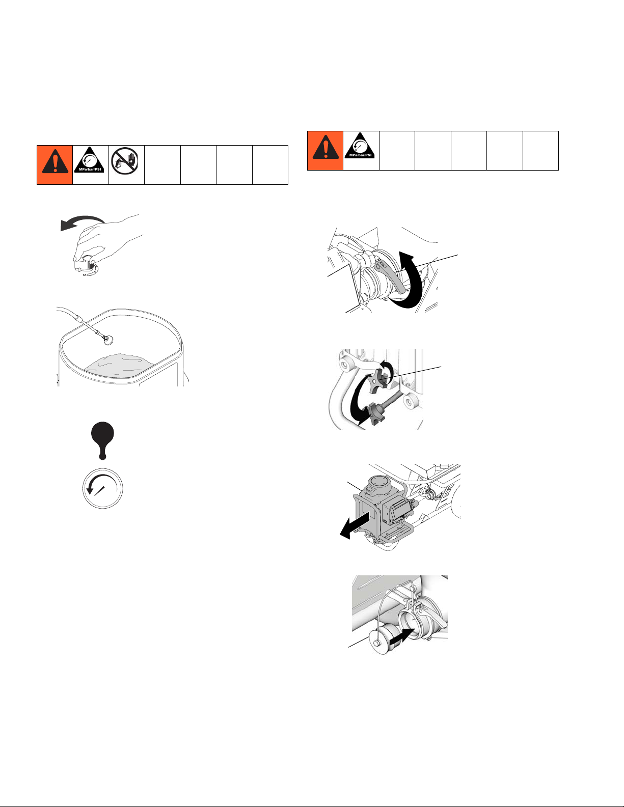
Pressure Relief Procedure
Pressure Relief
Procedure
1. Turn flow control knob to fully counterclockwise.
ti8793a
2. Place deflector in hopper or suitable container.
ti14876a
Power Module Removal
1. Perform Pressure Relief Procedure. Unplug power
cord.
2. Release hopper adapter clamp (158).
158
ti15684a
3. Loosen rod clamp knob (112) on front of pump module and push rod down.
112
3. Turn prime valve handle to PRESSURE RELIEF
position.
bar/psi
4. Display will read “----” when all pressure is relieved.
ti15614a
ti11675a
4. Lift and pull power module (153) off of unit.
NOTE: Power module weighs approximately 85 lb.
153
ti15623a
5. Install hopper plug (117) if needed.
117
ti15623a
4 3A0912A

Pump Removal
Power Module Installation
1. Remove hopper plug (117) if installed.
2. Replace power (153) module and insert pump outlet
into hopper inlet.
153
ti15625a
3. Pull rod clamp up and tighten knob (112) on front of
pump module.
112
ti11678a
4. Fasten hopper adapter clamp (158).
4. Loosen two screws (40) and remove pump rod
shield (48).
40
48
ti15619a
5. Turn flow control knob to a very low setting and turn
prime valve handle to TOOL FILL position (JOG
mode will appear in display). Use ON/OFF switch or
turn control knob OFF to stop pump when pin is
visible.
ti15620a
6. Use screwdriver to press pin (7b) out of pump.
7b
ti15617a
158
ti15683a
Pump Removal
1. Perform Pressure Relief Procedure, see page 4.
2. Remove Power Module, see page 4.
3. Disconnect material hose (79) from pump (18a).
79
NOTE: Pin should be removed by pressing the pin
out through the bottom side of the pump. Make sure
to control the pump pin when removing so that it
does not fall into the pump module.
7. Use hammer to loosen pump retaining nut (22).
22
ti15615a
8. Unscrew and remove pump (18a) from module.
18a
ti15618a
18a
ti15616a
3A0912A 5

Pump Removal
Pump Installation
1. Extend pump piston rod 1.5 in.
1.5 in.
ti7171a
2. Install pump pin (7b). Verify retaining spring is in
groove of connecting rod.
7b
ti13093a
NOTE: Pin should be installed from the top side of the
pump. Make sure to control the pump pin when installing
so that it does not fall into the pump module.
3. Push pump up until pump threads engage.
5. Align pump outlet to right side so that hose can be
reassembled.
ti15923a
6. Screw jam nut up toward drive housing until nut
stops. Tighten jam nut by hand, then tap 1/8
to 1/4 turn with a 20 oz. (maximum) hammer to
approximately 75± 5 ft-lb (102 N•m).
ti15925a
7. Replace pump rod shield (48) and torque two
screws (40) to 30 - 34 in-lb.
ti15924a
4. Screw in pump until threads are flush with drive
housing opening.
ti15621a
40
48
ti15619a
8. Reconnect material hose (79) to pump (18a).
79
18a
ti15616a
9. Replace Power Module, see page 5.
6 3A0912A

Pump Service
Pump Service
Disassemble the Pump
1. Perform Pressure Relief Procedure, page 4.
2. Perform Power Module Removal, page 4.
3. Perform Pump Removal, page 5.
4. Remove packing nut (312) and throat adjustment
spacer (302).
312
7. Tap piston rod out of cylinder with a hammer or flip
over and tap piston rod out against a bench.
8. Remove piston (311) from sleeve (306), or remove
sleeve from cylinder.
311
306
5. Unscrew intake valve (319) from cylinder (304).
304
319
6. Disassemble intake valve (319). Clean and inspect.
O-ring (315a) may require a pick for removal.
NOTE: if seat and ball need to be replaced, Carbide
Repair Kit 24F268 is available.
315a
319
COMPONENT RUPTURE HAZARD
Do not clean or wipe the piston valve threads. Cleaning
the piston valve threads could destroy the special sealing
patch and cause the piston valve to come loose during
operation, causing pump bursting and possible bodily
injury.
9. Unscrew piston valve (313) from piston rod (311).
Clean and inspect parts. The piston has a special
thread locking/sealing patch. Do not remove the
patch. The patch allows four disassembly/assembly
procedures before it is necessary to apply sealant to
threads.
313
311
3A0912A 7

Pump Service
10. Remove packings and glands from piston rod.
Discard packings and glands. Remove piston wiper
and back-up washer from piston rod. Discard piston
wiper and back-up washer.
11. Remove throat packings and glands from cylinder.
Discard throat packings and glands.
2. Install ball (315c) in piston rod. If thread sealant is
applied to piston valve threads, ensure that none
gets on ball.
315c
3. Tighten piston valve to 55 +/- 3 ft-lb.
Assemble the Pump
1. Soak all leather packings in SAE 30W oil for 1 hour
minimum prior to assembly. Stack male gland (315k)
on piston rod. Alternately stack UHMWPE and
packings (note orientation) on piston rod. Install
female gland (315f). The special sealing patch on
piston valve threads is good for four repackings.
Install piston wiper (315e) and back-up washer.
315f
315e
315j
315k
315g
4. Soak all leather packings in SAE 30W oil for 1 hour
minimum prior to assembly. Place male gland
(315p) in cylinder. Alternately stack UHMWPE and
packings (note orientation). Place female gland
(315g) in top of cylinder. Seat packings.
315q
315j
315g
315p
5. Install packing nut (312). Install throat adjustment
spacer (302) onto packing nut. Loosely install packing nut into cylinder.
312
302
8 3A0912A

Pump Service
6. Grease piston packings and sleeve top edge.
7. Carefully slide piston assembly into top of sleeve.
8. Grease top inch or two of piston rod that will go
through the cylinder throat packings.
10. Reassemble intake valve with new o-ring (315a),
seat (309a) and ball (315b). Seat may be flipped
over and used on other side. Clean seat thoroughly.
Place intake spring (315r) on top of ball guide (317).
317r
317
315b
309a
315a
11. Install intake valve on cylinder. If a wrench is used,
torque to 200 +/- 15 ft-lb. If a wrench is not used, be
sure intake valve is tight against cylinder.
9. Grease o-ring (315m) and place on sleeve. Slide
sleeve/piston rod assembly into bottom of cylinder.
Replace o-ring (315n) if desired. NOTE: O-ring
(315n) is not required for safe pump operation.
315m
12. Torque seal and packing nut (312) down onto throat
adjustment spacer (302) to 140 +/- 10 in-lb. Remove
throat adjustment spacer (302) when pump packings begin to leak after too much use. Then tighten
packing nut down until leakage stops or lessens.
This allows approximately 100 gallons of additional
operation before a repacking is required.
312
302
3A0912A 9

Pump 24E957 Service Reference
Pump 24E957
Service Reference
301
312
302
325
315q
315g315g315g315g
315p
311
326
304
315m
306
315j315j315j
315j315j315j
315k
315g315g315g315g
315f
315e
315d
315h
315c
313
315r
317
315b
309a
315a
315n
319
Pump 24E957 Parts List
Ref. Part Description Qty.
301 183171 PLUG 1
302 C20987 PACKING, o-ring 1
304 15W463 HOUSING, outlet 1
306 248979 SLEEVE, cylinder, chrome 1
309 24F268 KIT, seat, carbide
(includes 309a, 315a, 315b)
309a 15J038 SEAT, carbide 1
311 15W925 ROD, piston 1
312 15W963 NUT, packing 1
313 249177 VALVE, piston 1
315 24F267 KIT, pump repair
(includes 315a - 315r)
315a 107098 PACKING, o-ring 1
315b 102972 BALL, metallic 1
315c 107203 BALL, valve, check 1
315d 15J800 WASHER, back-up
315e 119636 WIPER, piston 1
315f 189588 GLAND, packing, female 1
315g 193722 PACKING, vee 8
315h 158918 SPRING, compression 1
315j 112591 PACKING, vee 6
315k 189585 GLAND, packing, male 1
315m 108822 PACKING, o-ring 2
315n 160325 PACKING, o-ring 1
315p 198768 GLAND, male 1
315q 194175 GLAND, female 1
315r 24E027 SPRING, intake ball 1
317 198505 GUIDE, ball 1
319 15X124 HOUSING, inlet 1
325 15D117 TUBE, fiber, pump 1
326 15Y925 FITTING, 5/8 jic x 1/2 npt 1
1
1
1
315m
Technical Data (Pump)
Maximum working pressure 2500 psi (172 bar, 17.2 MPa)
Fluid outlet size 1/2 npt(f)
Wetted parts stainless steel, PTFE, leather, zinc-plated carbon steel,
tungsten carbide, chrome plating, UHMWPE, nickel-plated iron, nickel-plated
carbon steel
10 3A0912A

Notes
Notes
3A0912A 11

Graco Standard Warranty
Graco warrants all equipment referenced in this document which is manufactured by Graco and bearing its name to be free from defects in
material and workmanship on the date of sale to the original purchaser for use. With the exception of any special, extended, or limited warranty
published by Graco, Graco will, for a period of twelve months from the date of sale, repair or replace any part of the equipment determined by
Graco to be defective. This warranty applies only when the equipment is installed, operated and maintained in accordance with Graco’s written
recommendations.
This warranty does not cover, and Graco shall not be liable for general wear and tear, or any malfunction, damage or wear caused by faulty
installation, misapplication, abrasion, corrosion, inadequate or improper maintenance, negligence, accident, tampering, or substitution of
non-Graco component parts. Nor shall Graco be liable for malfunction, damage or wear caused by the incompatibility of Graco equipment with
structures, accessories, equipment or materials not supplied by Graco, or the improper design, manufacture, installation, operation or
maintenance of structures, accessories, equipment or materials not supplied by Graco.
This warranty is conditioned upon the prepaid return of the equipment claimed to be defective to an authorized Graco distributor for verification of
the claimed defect. If the claimed defect is verified, Graco will repair or replace free of charge any defective parts. The equipment will be returned
to the original purchaser transportation prepaid. If inspection of the equipment does not disclose any defect in material or workmanship, repairs will
be made at a reasonable charge, which charges may include the costs of parts, labor, and transportation.
THIS WARRANTY IS EXCLUSIVE, AND IS IN LIEU OF ANY OTHER WARRANTIES, EXPRESS OR IMPLIED, INCLUDING BUT NOT LIMITED
TO WARRANTY OF MERCHANTABILITY OR WARRANTY OF FITNESS FOR A PARTICULAR PURPOSE.
Graco’s sole obligation and buyer’s sole remedy for any breach of warranty shall be as set forth above. The buyer agrees that no other remedy
(including, but not limited to, incidental or consequential damages for lost profits, lost sales, injury to person or property, or any other incidental or
consequential loss) shall be available. Any action for breach of warranty must be brought within two (2) years of the date of sale.
GRACO MAKES NO WARRANTY, AND DISCLAIMS ALL IMPLIED WARRANTIES OF MERCHANTABILITY AND FITNESS FOR A
PARTICULAR PURPOSE, IN CONNECTION WITH ACCESSORIES, EQUIPMENT, MATERIALS OR COMPONENTS SOLD BUT NOT
MANUFACTURED BY GRACO. These items sold, but not manufactured by Graco (such as electric motors, switches, hose, etc.), are subject to
the warranty, if any, of their manufacturer. Graco will provide purchaser with reasonable assistance in making any claim for breach of these
warranties.
In no event will Graco be liable for indirect, incidental, special or consequential damages resulting from Graco supplying equipment hereunder, or
the furnishing, performance, or use of any products or other goods sold hereto, whether due to a breach of contract, breach of warranty, the
negligence of Graco, or otherwise.
FOR GRACO CANADA CUSTOMERS
The Parties acknowledge that they have required that the present document, as well as all documents, notices and legal proceedings entered into,
given or instituted pursuant hereto or relating directly or indirectly hereto, be drawn up in English. Les parties reconnaissent avoir convenu que la
rédaction du présente document sera en Anglais, ainsi que tous documents, avis et procédures judiciaires exécutés, donnés ou intentés, à la suite
de ou en rapport, directement ou indirectement, avec les procédures concernées.
Graco Information
For the latest information about Graco products, visit www.graco.com.
TO PLACE AN ORDER, contact your Graco distributor or call 1-800-690-2894 to identify the nearest distributor.
All written and visual data contained in this document reflects the latest product information available at the time of publication.
Graco reserves the right to make changes at any time without notice.
Original instructions. This manual contains English. MM 3A0912
Graco Headquarters: Minneapolis
International Offices: Belgium, China, Japan, Korea
GRACO INC. P.O. BOX 1441 MINNEAPOLIS, MN 55440-1441
Copyright 2010, Graco Inc. is registered to ISO 9001
www.graco.com
 Loading...