

Operation
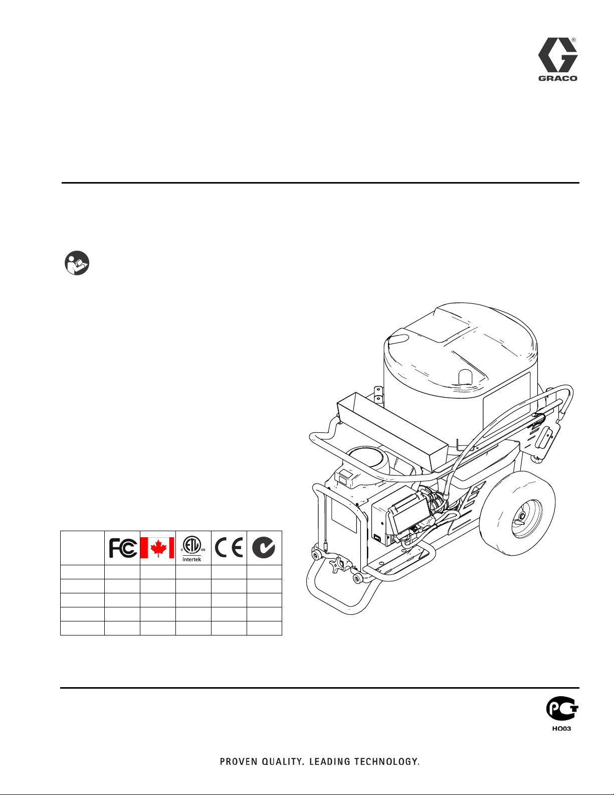
Drywall Feed Pump
U.S. Patents Pending: 61/315,288; 61/315/322; 61/316,013; 61/316,010
- For water-based materials only -
- Not for use in explosive atmospheres -
- Not for use with quick-set materials -
READ ALL WARNINGS AND INSTRUCTIONS
Read all warnings and instructions in this manual.
Save these instructions.
Maximum Working Pressure 2500 psi (17.2 MPa, 172 bar)
Model 257100: 120V NA ETL
Model 258906: 240V Euro Multicord
Model 258907: 110V UK, CE
Model 262288: 120V NA
Model 262300: 240V Euro CE Cord
3A0245A
ENG
Agency Approvals:
257100 ✓✓✓
258906 ✓✓
258907 ✓
262288 ✓✓
262300 ✓✓
ti14873a
Warning
Warning
The following warnings are for the setup, use, grounding, maintenance, and repair of this equipment. The exclamation point symbol alerts you to a general warning and the hazard symbols refer to procedure-specific risks. When these symbols appear in the
body of this manual, refer back to these Warnings. Product-specific hazard symbols and warnings not covered in this section may
appear throughout the body of this manual where applicable.
WARNING
WARNINGWARNINGWARNING
ELECTRIC SHOCK HAZARD
This equipment must be grounded. Improper grounding, setup, or usage of the system can cause electric shock.
• Turn off and disconnect power cord before servicing equipment.
• Use only grounded electrical outlets.
• Use only 3-wire extension cords.
• Ensure ground prongs are intact on power and extension cords.
• Do not expose to rain. Store indoors.
SKIN INJECTION HAZARD
High-pressure fluid from dispensing device, hose leaks, or ruptured components will pierce skin. This may look like
just a cut, but it is a serious injury that can result in amputation. Get immediate surgical treatment.
• Engage trigger lock when not dispensing.
• Do not point dispensing device at anyone or at any part of the body.
• Do not put your hand over the fluid outlet.
• Do not stop or deflect leaks with your hand, body, glove, or rag.
• Follow the Pressure Relief Procedure when you stop dispensing and before cleaning, checking, or servicing
equipment.
• Tighten all fluid connections before operating the equipment.
• Check hoses and couplings daily. Replace worn or damaged parts immediately.
FIRE AND EXPLOSION HAZARD
Flammable fumes, such as solvent and paint fumes, in work area can ignite or explode. To help prevent fire and
explosion:
• Do not dispense flammable or combustible materials near an open flame or sources of ignition such as
cigarettes, motors, and electrical equipment.
• Material or solvent flowing through the equipment is able to result in static electricity. Static electricity creates a
risk of fire or explosion in the presence of material or solvent fumes. All parts of the system, including the pump,
hose assembly, dispenser, and objects in and around the work area shall be properly grounded to protect against
static discharge and sparks. Use Graco conductive or grounded high-pressure airless material hoses.
• Verify that all containers and collection systems are grounded to prevent static discharge.
• Connect to a grounded outlet and use grounded extensions cords. Do not use a 3-to-2 adapter.
• Do not use a material or a solvent containing halogenated hydrocarbons.
• Keep work area well-ventilated. Keep a good supply of fresh air moving through the area. Keep pump assembly
in a well ventilated area.
• Do not smoke in the work area.
• Do not operate light switches, engines, or similar spark producing products in the work area.
• Keep area clean and free of material or solvent containers, rags, and other flammable materials.
• Know the contents of the materials and solvents being dispensed. Read all Material Safety Data Sheets (MSDS)
and container labels provided with the materials and solvents. Follow the material and solvents manufacturer’s
safety instructions.
• Fire extinguisher equipment shall be present and working.
• Drywall feed pump generates sparks. When flammable liquid is used in or near the drywall feed pump or for
flushing or cleaning, keep unit at least 20 feet (6 m) away from explosive vapors.
2 3A0245A
Warning
WARNING
WARNINGWARNINGWARNING
MOVING PARTS HAZARD
Moving parts can pinch, cut or amputate fingers and other body parts.
• Keep clear of moving parts.
• Do not operate equipment with protective guards or covers removed.
• Pressurized equipment can start without warning. Before checking, moving, or servicing equipment, follow the
Pressure Relief Procedure and disconnect all power sources.
EQUIPMENT MISUSE HAZARD
Misuse can cause death or serious injury.
• Always wear appropriate gloves, eye protection, and a respirator or mask when dispensing.
• Do not operate or dispense near children. Keep children away from equipment at all times.
• Do not overreach or stand on an unstable support. Keep effective footing and balance at all times.
• Stay alert and watch what you are doing.
• Do not leave the unit energized or under pressure while unattended. When the unit is not in use, turn off the unit and
follow the Pressure Relief Procedure for turning off the unit.
• Do not operate the unit when fatigued or under the influence of drugs or alcohol.
• Do not kink or over-bend the hose.
• Do not expose the hose to temperatures or to pressures in excess of those specified by Graco.
• Do not use the hose as a strength member to pull or lift the equipment.
PRESSURIZED ALUMINUM PARTS HAZARD
Use of fluids that are incompatible with aluminum in pressurized equipment can cause serious chemical reaction and
equipment rupture. Failure to follow this warning can result in death, serious injury, or property damage.
• Do not use 1,1,1-trichloroethane, methylene chloride, other halogenated hydrocarbon solvents or fluids containing such
solvents.
• Many other fluids may contain chemicals that can react with aluminum. Contact your material supplier for compatibility.
PERSONAL PROTECTIVE EQUIPMENT
You must wear appropriate protective equipment when operating, servicing, or when in the operating area of the equipment
to help protect you from serious injury, including eye injury, hearing loss, inhalation of toxic fumes, and burns. This
equipment includes but is not limited to:
• Protective eyewear, and hearing protection.
• Respirators, protective clothing, and gloves as recommended by the fluid and solvent manufacturer.
3A0245A 3
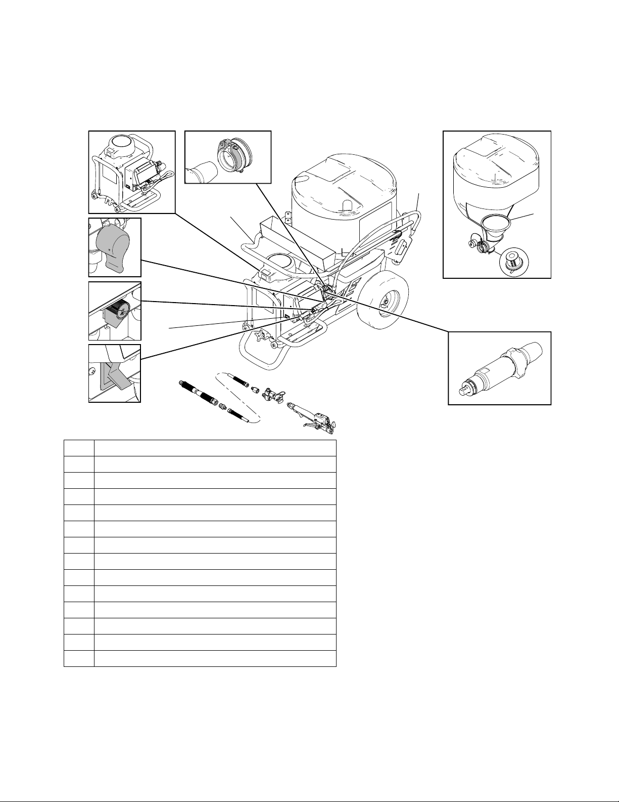
Component Identification (Unit)
Component Identification (Unit)
K
A
G
B
C
E
D
F
A
Pump Module
B
Prime/Tool Fill/Recirculation Valve/Pressure Relief
C
Flow Control Knob
D
ON/OFF Switch
E
15/20 Amp Switch (North America only)
F
Material Hoses
G
Movable Handle
H
Pump Connector
J
Prime Hose
K
Hopper
L
Hopper Plug
M
Expandable Plug
N
Pump
P
Material Screen
H
J
P
L
M
ti14874a
N
4 3A0245A
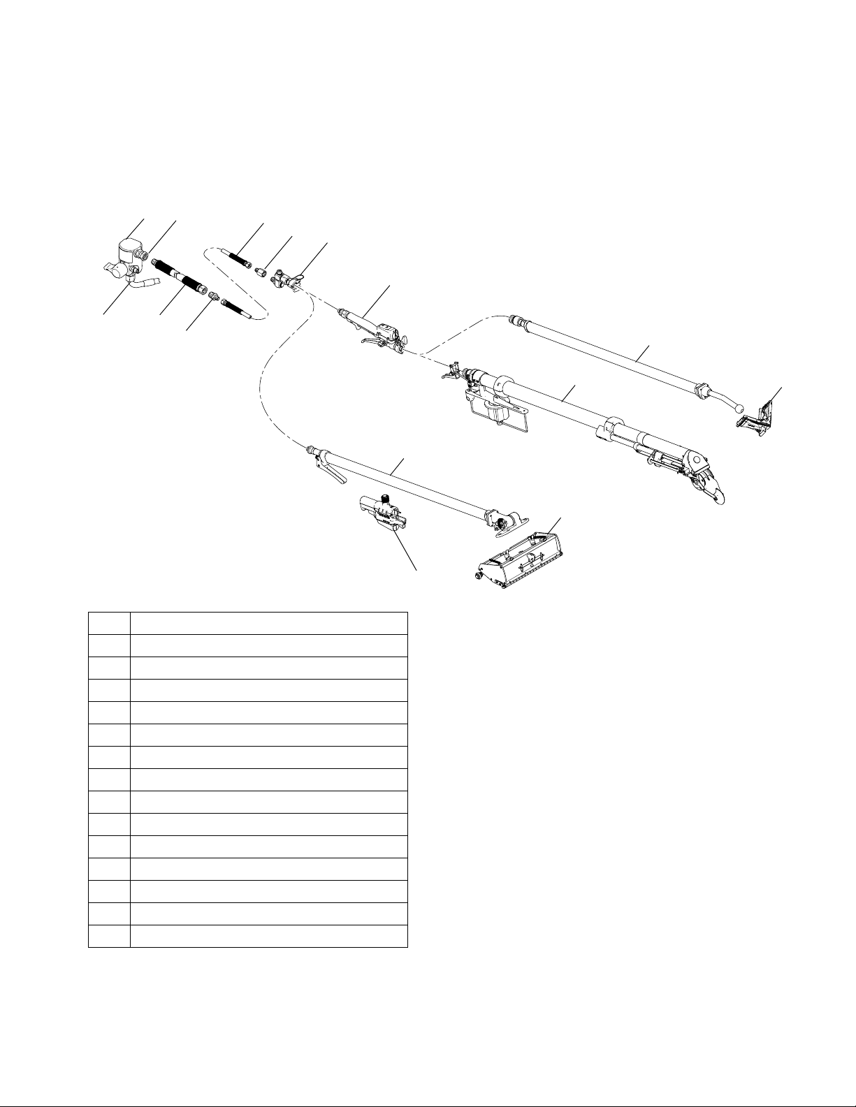
Component Identification (Hoses and Tools)
Component Identification (Hoses and Tools)
AA
BB
FF
GG
HH
JJ
CC
AA
BB
CC
DD
EE
FF
GG
HH
JJ
KK
LL
MM
NN
PP
RR
DD
EE
Fluid Manifold
Fluid Outlet
Fluid Inlet
Hose 1/2 in. x 50 ft (max 150 ft)
Fitting 1/2 in. x 1/4 in.
Hose 1/4 in. x 15 ft
Coupling
Z Swivel with Quick-Connect Clamp
Inline Valve Controller
Box Slide Controller
Box Tool Handle
Box Tool Head
Tape Tool
Corner Tool Handle
Corner Tool Head
LL
KK
MM
NN
PP
RR
ti15676a
3A0245A 5
Grounding
Grounding
GROUNDING INSTRUCTIONS (North America)
This appliance is rated more than 15 A and is for use
on a circuit having a nominal rating of 120 V and is factory equipped with a specific electric cord and plug. No
adapter should be used with this appliance. If the appliance must be reconnected for use on a different type of
electric circuit, the connection should be made by qualified service personnel; and after the connection, the
appliance should comply with all local codes and ordinances.
Consult a qualified electrician if there is any doubt as to
whether an outlet box is properly grounded.
GROUNDING INSTRUCTIONS (Europe)
The sprayer must be grounded. Grounding reduces the
risk of static and electric shock by providing an escape
wire for the electrical current due to static build up or in the
event of a short circuit.
FCC Notice (FCC ID: JHICED1)
Model Number: DFS150
This device complies with Part 15 of the FCC rules.
Operation is subject to the following two conditions:
• This device may not cause harmful interference.
• This device must accept any interference that may
be received, including interference that may cause
undesired operation.
Changes or modifications not expressly approved by
Graco, Inc. could void the user's authority to operate this
equipment.
IC Notice (IC: 4840ACED1)
This product meets the applicable Industry Canada
technical specifications/Le présent materiel est conforme aux specifications techniques applicables
d’Industrie Canada.
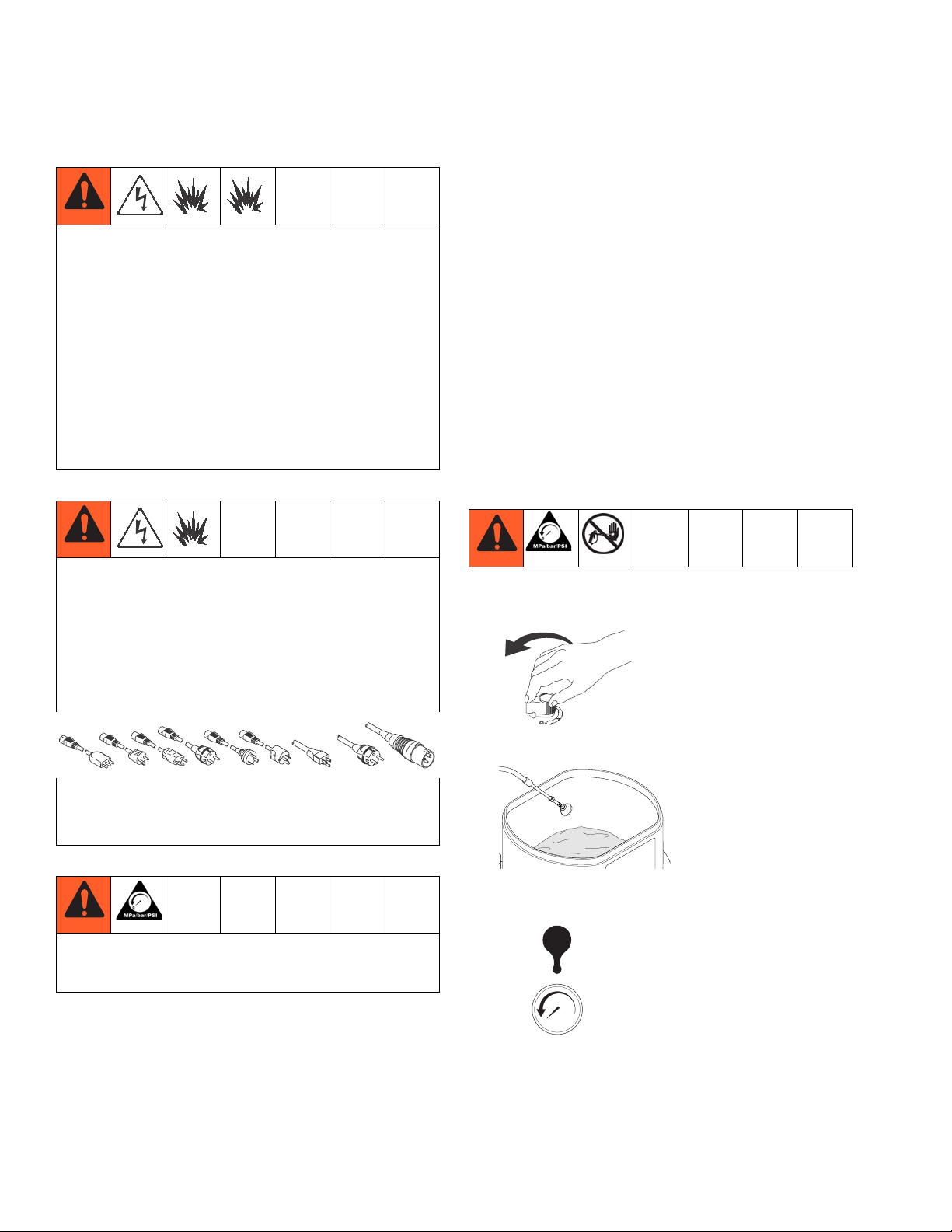
Pressure Relief Procedure
1. Turn flow control knob fully counterclockwise to OFF
position.
The sprayer cord includes a grounding wire with an
appropriate grounding contact.
The plug must be plugged into an outlet that is properly
installed and grounded in accordance with all local
codes and ordinances.
Do NOT tamper with relief valve or devices that control
maximum flow control during normal operation. Bodily
injury and/or damaged to equipment can occur.
ti8793a
2. Place deflector in hopper or suitable container.
ti14876a
3. Turn prime valve handle to PRESSURE RELIEF
position.
ti15614a
bar/psi
4. Display will read “----” when all pressure is relieved.
If display does not reach 0, the hose or inline valve
are clogged and prime/tool fill/ recirculation valve is
plugged.
6 3A0245A
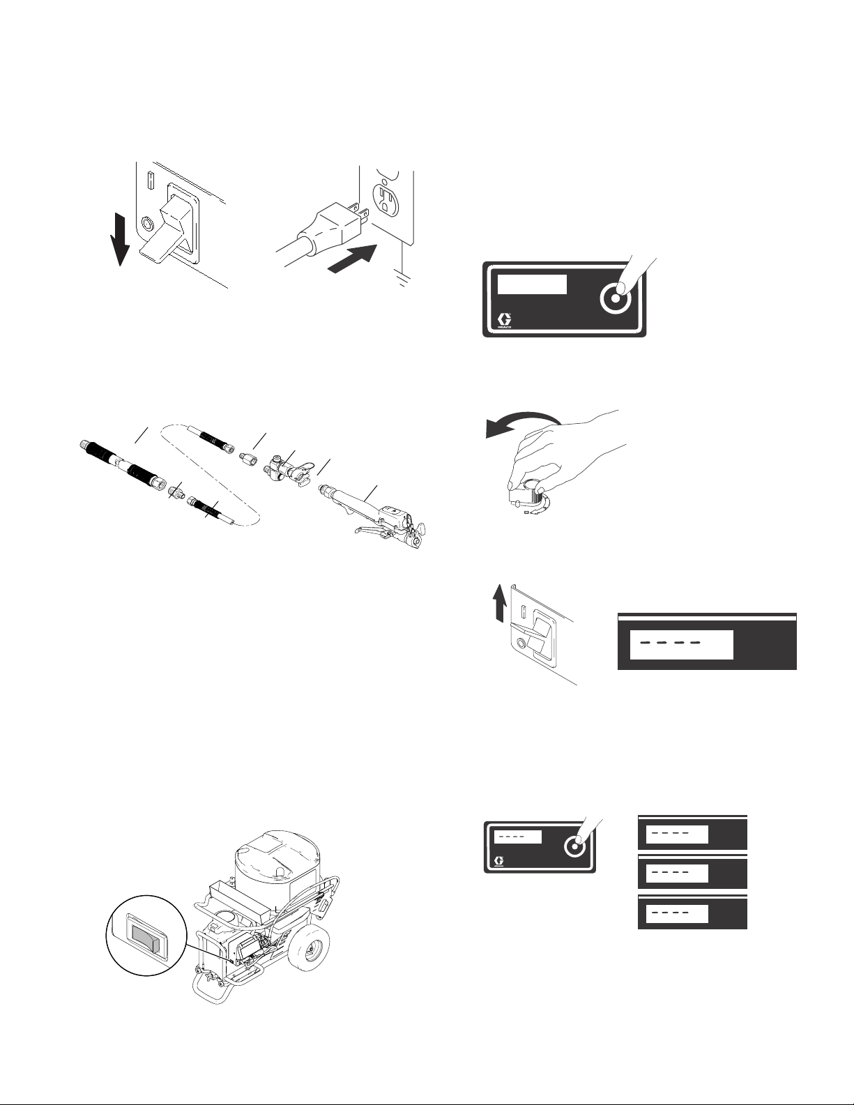
Setup
Setup
1. Turn power switch to OFF and connect power cord.
ti4265a
ti2810a
ti4265a
2. Connect material hose (DD) to fluid manifold outlet
(BB).
NOTE: Up to 150 ft of 1/2 in. plus 15 ft. x 1/4 in. hose
can be connected to the unit. If desired flow rate is not
obtainable, reduce hose length or add additional water
to material mixture.
BB
DD
EE
FF
GG
HH
JJ
ti15635a
3. Use fitting (EE) to connect to hose (FF) and hose
(DD).
Digital Tracking System (DTS)
Operation Main Menu
Short press to move to next display. Press and hold (5 seconds) to change units or reset.
ti13605a
1. Turn flow control knob fully counterclockwise to OFF
position. Perform Pressure Relief Procedure, page
6.
ti8793a
2. Turn power ON. Pressure display appears. Dashes
will not appear unless pressure is less than 200 psi
(14 bar, 1.4 MPa).
4. Use coupling (GG) to connect hose (FF) and Z
swivel (HH).
5. Connect Inline Controller Valve (JJ) if taping or finishing corners.
6. Connect selected finishing tool using supplied
quick-connect clamps. See Using Finishing Tools,
page 11.
7. Select 15A/20A setting based on your circuit rating
(North America only).
NOTE: 20A setting will produce the best performance.
20
ti15622a
psi
ti4266a
ti13621a
Change Display Units
Press and hold DTS button for 5 seconds to change pressure units (psi, bar, MPa) to desired units. Selection of bar
or MPa changes gallons to liters x 10. To change display of
units, DTS must be in flow control mode and pressure must
be at zero.
Psi
ti13620a
Psi
bar
MPa
ti13604a
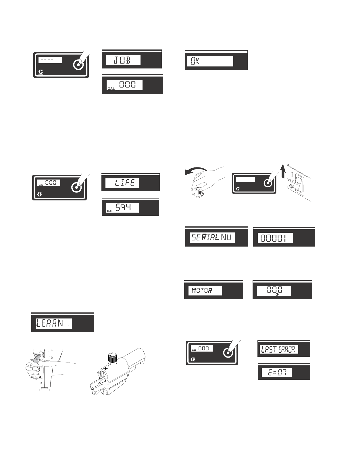
Job Gallons
1. Short press DTS button to move to Job Gallons (or
liters x 10).
3A0245A 7
Setup
Psi
ti13612a
ti13667a
ti13620a
ti13610a
NOTE: JOB scrolls past, then the number of gallons dispensed displays.
2. Press and hold to reset to zero.
Lifetime Gallons
1. Short press DTS button to move to LIFE gallons (or
liters x 10). LIFE scrolls briefly, then the number of
gallons dispensed displays.
ti13617a
ti13601a
ti13611a
Learn the Controller
This unit uses two different controllers: an inline valve controller for taping and corner finishing, and a box slide controller for box finishing. Each time you change controllers,
perform the following steps so the unit can learn the controller.
1. Turn flow control knob fully counterclockwise to OFF
position.
NOTE: You must be facing the unit and be no more than 10
ft away to learn the controller. The unit can only be
operated by one learned controller at a time.
Secondary Menu - Stored Data
1. Perform Pressure Relief Procedure, see page 6.
2. To access Secondary Menu, make sure flow control
knob is turned fully counter-clockwise to the OFF
position. Then turn power switch on while holding
DTS button down.
ti8793a
ti13605a
3. SERIAL NUMBER scrolls past and then serial number (e.g. 00001) displays.
ti13622a
4. Short press DTS button and MOTOR HOURS
scrolls past and then total motor run hours are displayed.
ti4266a
ti7362a
2. Push digital display button 3 times until LEARN
appears on display screen.
ti13618a
ti13619a
5. Short press DTS button. LAST ERROR CODE
ti13627a
scrolls by and last error code is displayed (e.g.
E=07). See Electrical Problems, page 19.
3. Pull trigger on controller.
ti13615a
ti13601a
ti15626a
ti15676a
ti13607a
4. OK will then appear on display screen (if not, see
Troubleshooting).
8 3A0245A
Setup
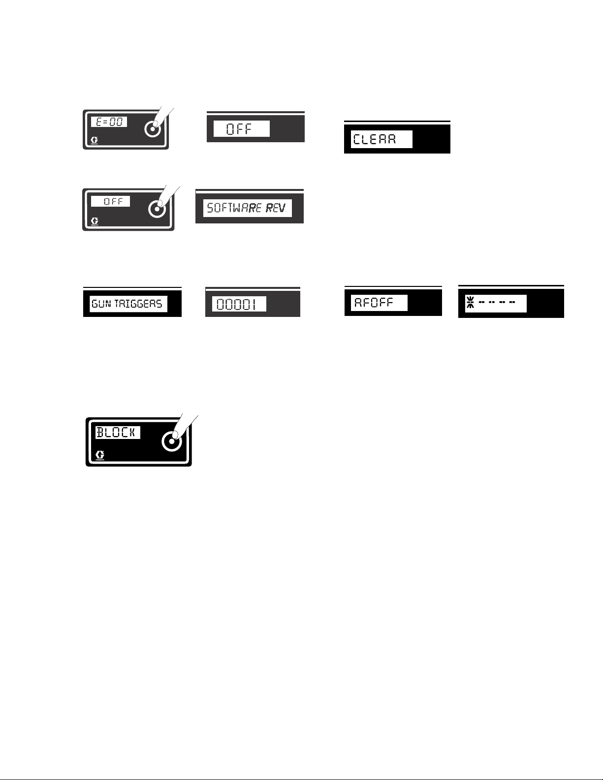
6. Press and hold DTS button to clear error code to
zero.
ti13608a
ti13614a
7. Short press to move to SOFTWARE REV.
ti13613a
ti13623a
8. Short press to display number of GUN TRIGGERS
logged.
ti15694a
ti7362a
9. Short press to enter BLOCK mode. Hold DTS button in to block any active outside RF signals in the
area other than the current learned controller. The
screen will display the number of unwanted signals
being blocked. Up to 5 unwanted RF signals can be
blocked.
10. Short press to enter CLEAR mode. Hold in DTS
button to clear all RF signals that were being
blocked.
ti15693a
11. Short press to RF ON/OFF mode (this is used for
Troubleshooting only). To turn RF off and enter pressure control mode, make sure flow control knob is at
zero. Hold DTS button until screen displays RFOFF.
Turn power switch OFF, then turn back ON. The display will show an asterisk to indicate that it is in
pressure control mode.
To return to flow control mode, turn power switch
OFF for approximately 45 seconds.
psi
ti15695a
ti15692a
ti15691a
NOTE: To see the number of blocked signals, press and
hold the DTS button.
3A0245A 9
Prime Pump
Prime Pump
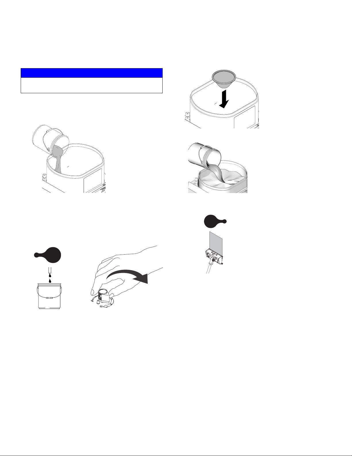
NOTICE
Do not use with quick-set materials. They can harden
inside the unit and hose.
1. Mix material in separate bucket.
2. Add 1-2 gallons (4-8 liters) of material to hopper.
ti15747a
3. Place prime hose deflector into hopper or empty
bucket. NOTE: Keep deflector shield wet once it is in
use.
4. Turn power ON and turn prime valve handle to
PRIME. Turn flow control knob clockwise to start
pumping.
ti15746a
6. Add the remaining material to hopper.
ti11670a
7. After unit is primed, turn prime valve handle to
APPLY FINISH position.
ti15612a
ti15613a
ti8794a
5. Install material screen (P).
10 3A0245A
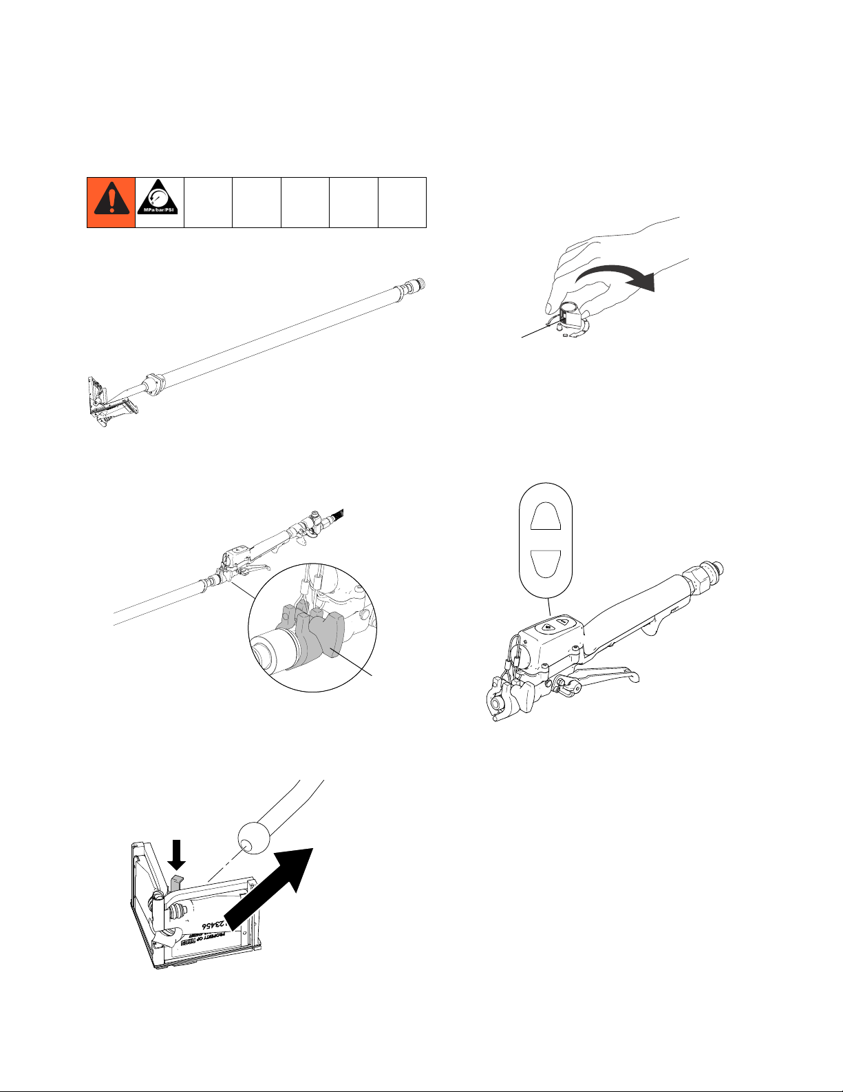
Using Finishing Tools
Corner Finishing
Using Finishing Tools
3. Use flow control knob (C) to set material flow rate.
Turn flow control knob clockwise to increase
material flow.
ti8794a
C
ti15681a
1. Attach corner finisher inlet swivel to inline valve
controller (JJ) valve using quick-connect clamp (QC)
attached to valve.
ti15666a
QC
2. Press pin on top of corner finisher head to install
onto handle.
NOTE: Fine flow rate adjustments can be made
using “+” and “-” buttons on inline valve controller.
Flow rate can only be adjusted relative to position of
flow control knob. The fine flow rate can only go
down from, and up to the flow control knob setting.
+
-
ti15675a
4. Pull trigger and work from top to bottom of vertical
angles and from one end to other on ceiling angles.
5. Use drywall knife to detail corner and ceiling angle
intersections.
ti15665a
3A0245A 11

Using Finishing Tools
Flat Box Finishing
ti15676a
1. Attach male inlet of box finisher to the Z-swivel
assembly using quick-connect clamp attached to
Z-swivel.
2. Install Box Slide Controller (KK) on box finish handle
as shown.
TT
KK
ti15668a
5. Place flat box at end of joint.
6. Pull trigger and lead with handle and draw the tool
along the joint.
7. Near middle of the joint, remove flat box from joint
surface by applying brake and using a sweeping
motion.
8. Adjust hand position and begin again at other end of
joint.
9. Again, draw flat box along joint up to previous
stopping point and remove box from joint surface by
applying brake and using a sweeping motion.
10. Use drywall knife to eliminate seams and overlap.
NOTE: To remove RF Controller, use both thumbs and
press down as shown:
NOTE: The Box Slide Controller Brake (TT) allows the
controller to be positioned on the handle. Make sure
that the brake is fully loosened when installing the controller on the handle.
3. Install flat finish box on handle using attached wing
nuts.
4. Use flow control knob (C) to set material flow rate.
Turn flow control knob clockwise to increase
material flow.
C
ti8794a
ti15673a
12 3A0245A

Automatic Taping
Using Finishing Tools
1. Remove creaser wheel trigger pin.
ti15679a
2. Attach taper tool to inline valve.
ti15748a
5. Use flow control knob (C) to set material flow rate.
Turn flow control knob clockwise to increase
material flow.
ti8794a
C
NOTE: Fine flow rate adjustments can be made
using “+” and “-” buttons on inline valve controller.
Flow rate can only be adjusted relative to position of
flow control knob. The fine flow rate can only go
down from, and up to the flow control knob setting.
+
-
3. Position creaser wheel trigger and insert pin into
trigger assembly.
ti15678a
4. Load tape into taper tool.
ti15682a
ti15675a
6. Place one hand on taper control tube and one hand
on Inline Controller Valve (JJ) while in use.
7. Place tape at bottom of joint (slide tube forward to
feed tape).
8. Pull trigger and roll tape over seam keeping taper
head wheels in contact with wall.
9. When taper reaches approximately 3 in. (7.5 cm)
from end of seam, stop completely and pull tube
back to cut tape.
10. Use drywall knife to detail seams and overlap.
NOTE: Clean all tools thoroughly after every use. Use
a brush and water to remove all joint compound from
tools. Once tools have been cleaned, lightly oil using
any light machine oil.
NOTE: When taping ceilings or corner seams, the
creaser wheel can be actuated to push the tape into
the seam by using the creaser wheel trigger.
3A0245A 13
Storage
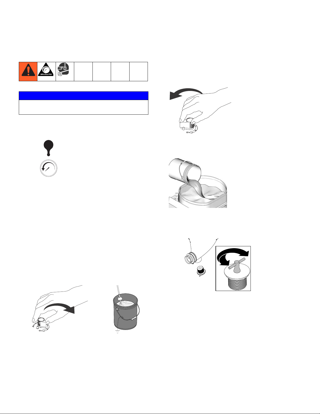
Storage
NOTICE
Do not use with quick-set materials. They can harden
inside the unit and hose.
1. Perform Pressure Relief Procedure, page 6 (prime
valve handle in down position). Leave prime valve
handle in PRESSURE RELIEF position.
ti15614a
bar/psi
3. Remove remaining material from hopper.
4. Turn pump control fully counter-clockwise to shut
pump off.
ti8793a
5. Fill material hopper with water and run pump to
flush unit. Run water through material hose, tools
and drain line thoroughly flush system.
2. Spray water mist on top of any remaining material in
the hopper and cover hopper with lid.
3. Cover valve and tool ends to keep joint compound
from hardening.
4. Submerge deflector of prime hose in bucket or cover
to keep join compound from hardening.
Cleanup
1. Perform Pressure Relief Procedure, page 6 (prime
valve handle in down position).
2. Flush unused material from hopper, hose, and
prime hose.
ti8794a
ti14877a
ti11670a
6. Clean all tools.
7. Remove drain plug from hopper. Flush with water.
Clean and install drain plug.
ti14879a
14 3A0245A
Troubleshooting
Motor Will Not Operate (See flow chart, page 25)
PROBLEM CAUSE SOLUTION
Troubleshooting
Basic fluid flow problems Flow control knob turned up but unit is not
pumping.
Flow control knob setting. Motor will not run if
at minimum setting (fully counterclockwise).
Valve or filter may be clogged. Relieve pressure and clear clog.
Basic mechanical problems Frozen material. Place drywall feed pump in warm area
Hardened material. Clean unit.
Motor. Remove drive housing assembly.
Try to rotate fan by hand.
Basic electrical problems Motor control board. Board shuts down and
displays error code.
No power. Check power source.
Extension cord. Check extension cord conti-
nuity with volt meter.
Power supply cord. Inspect for damage such
as broken insulation or wires.
Check that motor leads are securely fastened
and properly mated.
ON/OFF Switch. See Unit Will Not Run, page 25.
Check all terminals for damage or loose fit. Replace damaged terminals and
Battery has no power Battery voltage depleted. Replace battery. Graco part
RF problems See RF Problems, page 18.
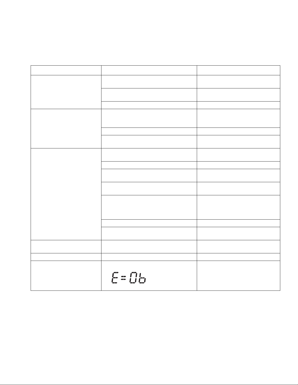
Motor is hot Digital display shows E=06 Move unit to shaded, cooler area if pos-
Learn the Controller, see page 9.
Check battery voltage.
Slowly increase flow setting to see if
motor starts.
to thaw. Do not start unit until thawed
completely.
Replace motor if fan won't turn.
See Control Board Diagnostics.
Replace extension cord.
Replace power supply cord.
Replace loose terminals; crimp to
leads. Be sure terminals are firmly connected. Clean circuit board terminals.
Securely reconnect leads.
reconnect securely.
number:15X949 (CR123A-3V Lithium)
sible. Be sure ambient temperature
where unit is located is no more than
90°F and unit is not located in direct
sun.
3A0245A 15

Troubleshooting
Low or Fluctuating Output
PROBLEM CAUSE SOLUTION
Low output Pump is worn or clogged. Service pump. Check piston and intake
valves for wear or obstructions.
Plugged prime/tool fill/ recirculation
valve
Plugged hose, swivel, tool, or inline
valve
Material hose length. Longer hose
length reduces drywall feed pump performance.
Pump hopper adapter connections are
loose.
Check electrical supply voltage with volt
meter. Meter must read:
210-255 Vac for 220-240 Vac models;
85-130 Vac for 100-120 Vac models.
Low voltages reduce drywall feed pump
performance.
Extension cord size and length; must be
at least 12 awg (1.0 mm2) wire and no
longer than 90 m (295 ft). Longer cord
lengths reduce drywall feed pump
performance.
Leads from motor to flow control circuit
board for damaged or loose wires or
connectors. Inspect wiring insulation
and terminals for signs of overheating.
Flow control knob is turned down. Turn flow control knob fully clockwise.
Material has dried and plugged the
prime/tool fill/ recirculation valve.
Debris or pack-out in tool, swivel, hose,
or inline valve
Reduce hose length or thin material.
Use 20A setting if available.
Tighten any loose connections.
Replace pump hopper adapter if
cracked or punctured.
Try a different outlet.
Replace with a correct, grounded
extension cord.
Be sure male terminal blades are centered and firmly connected to female
terminals. Replace any loose terminal
or damaged wiring. Securely reconnect
terminals.
Make sure flow control knob is properly
installed to allow full clockwise position.
Aim hose into waste pail. Turn prime
valve handle from TOOL FILL to PRESSURE RELIEF and then back to TOOL
FILL. If valve remains plugged, see
Pressure Relief Procedure, page 6.
Check and clean out all flow components. Perform Pressure Relief Proce-
dure, page 6.
16 3A0245A

Troubleshooting
Low or Fluctuating Output (continued)
PROBLEM CAUSE SOLUTION
Motor runs and pump strokes No material supply. Refill hopper and re-prime pump.
Clean hopper strainer.
Loose fittings. Tighten; use thread sealant or sealing
tape on threads if necessary.
Motor runs but pump does not
stroke
Motor intermittently stops while
applying material
Intake valve ball and piston ball are not seating properly.
Leaking around throat packing nut which may
indicate worn or damaged packings.
Pump rod damage. Repair pump.
Displacement pump pin (damaged or miss-
ing).
Connecting rod assembly is damaged. Replace connecting rod assembly.
Gears or drive housing. Inspect drive housing assembly and
Remove intake and piston valves and
clean. Check balls and seats for nicks or
obstructions; replace if necessary, page
18. Also check piston valve seat for
hardened material or nicks and replace
if necessary. Clean hopper before using
to remove particles that could clog
pump.
Replace packing, page 18.
Replace pump pin if missing. Be sure
retainer spring (76) is fully in groove all
around connecting rod.
gears for damage. Replace if needed.
See RF Problems, page 18.
Electrical Short
PROBLEM CAUSE SOLUTION
Building circuit breaker opens as
soon as power switch is turned on.
CAUTION
Any short in any part of the motor
power circuit will cause the control
circuit to inhibit drywall feed pump
operation. Correctly diagnose and
repair all shorts before checking
and replacing control board.
Building circuit breaker opens as
soon as unit is plugged into outlet
and unit is NOT turned on.
Drywall feed pump quits after unit
operates for 5 to 10 minutes.
Electrical wiring insulation damaged, terminals fit loose or are damaged. Also wires
between motor control and motor.
Motor armature is shorted. Replace motor. Inspect windings for
Motor control board. Replace with a new control board if
Basic Electrical Problems, see page 15. Perform necessary procedures.
For damaged or pinched wires in pressure
control.
Basic Electrical Problems. Perform necessary procedures.
Check electrical supply with volt meter.
Meter must read:
210-255 Vac for 220-240 Vac models;
85-130 Vac for 100-120 Vac models.
Repair or replace damaged wiring or
terminals. Securely reconnect all
wires.
burns. Perform motor control board
diagnosis.
necessary. Perform motor control
board diagnosis.
Replace damaged parts.
If voltage is too high, do not operate
drywall feed pump until corrected.
3A0245A 17

Troubleshooting
RF Problems
PROBLEM CAUSE SOLUTION
Unwanted signal will not allow unit
to learn the controller.
RF controller will not learn. Battery is depleted. Replace battery
Interference in RF signal Signal is out of range. Reposition the unit. Use optional exter-
Unwanted RF signal. Undesired controller is
active and in close proximity.
Unit has not learned the controller. Learn the controller, see page 8.
Controller RF has been blocked. See CLEAR procedure, page 9.
Controller is too far away or is not facing the
unit.
Stop unwanted RF signal by deactivating the controller. Use BLOCK feature
on Secondary Menu, see page 8.
(CR123A Lithium 3V).
Move to within 10 ft and face the unit.
Hold the controller away from your
body.
nal remote antenna.
18 3A0245A
Electrical Problems
Troubleshooting
Symptom: Unit does not run or stops running.
Perform Pressure Relief Procedure; page 6.
• Plug unit into correct voltage, grounded outlet
• Set power switch OFF for 45 seconds and then ON
again (this ensures drywall feed pump is in default
flow control mode).
• Turn flow control knob clockwise 1/2 turn
• Trigger learned controller
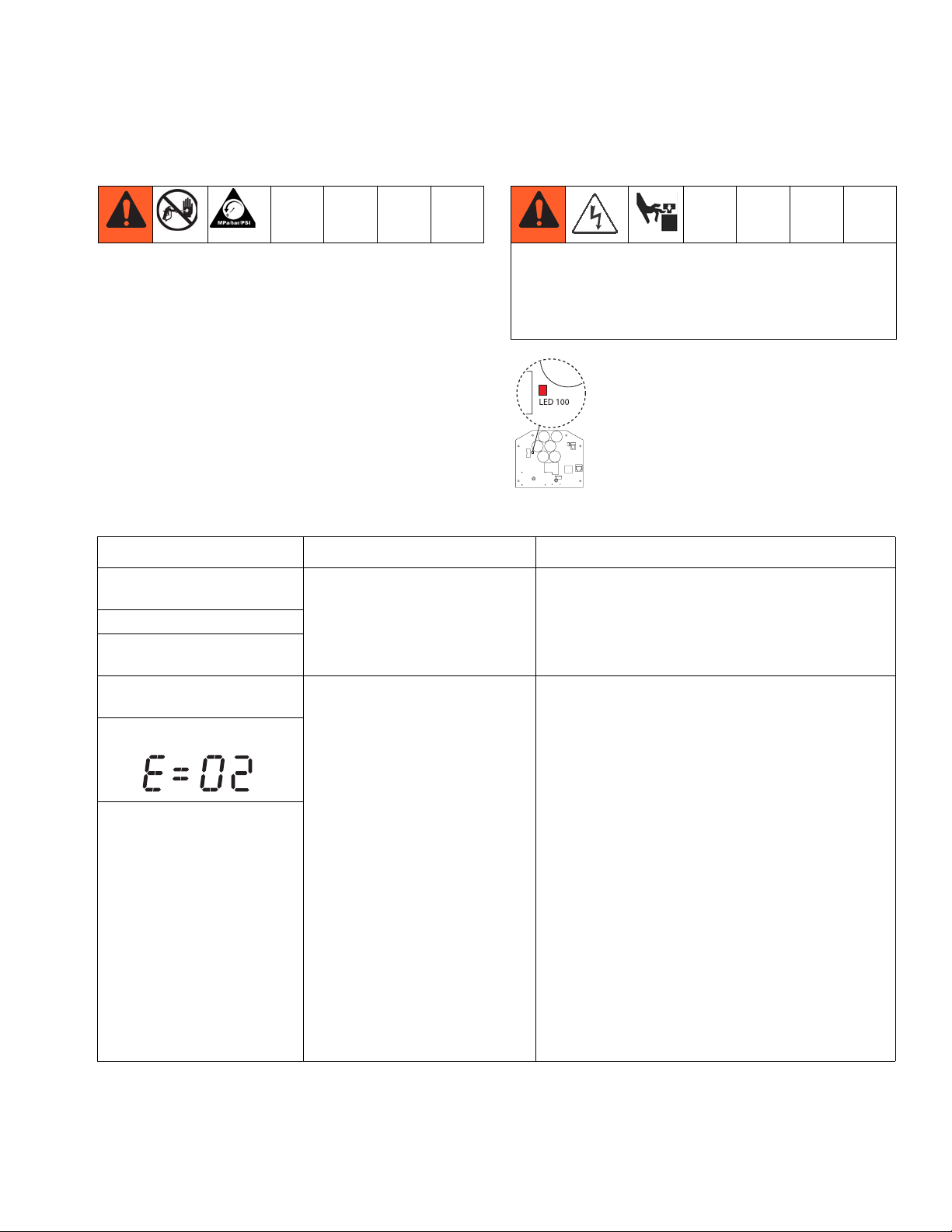
To avoid electrical shock or moving parts hazards when
covers are removed for troubleshooting, wait 45 seconds after unplugging power cord for stored electricity
to dissipate. Keep clear of electrical and moving parts
during troubleshooting procedures.
If no digital display is available, use the control board status light to troubleshoot problems. turn ON/OFF switch to OFF, remove
control cover and then turn power back ON.
Observe status light. Blinking LED total
count equals digital error code (example: two
blinks equals E=02).
• View digital display
TYPE OF PROBLEM WHAT TO CHECK HOW TO CHECK
Drywall feed pump does not
run at all
Digital display is blank
Control board status light
never lights
Drywall feed pump does not
run at all
Digital display shows E=02
Control board status light
blinks 2 times repeatedly
See flow chart, page 25.
Check transducer or transducer
connections.
1. Make sure there is no pressure in the system (see
Pressure Relief Procedure, page 6). Check fluid
path for clogs.
2. Make sure a minimum of 50 ft of hose is connected
to the unit.
3. Set drywall feed pump to OFF and disconnect power
to drywall feed pump.
4. Check transducer and connections to control board.
5. Disconnect transducer from control board socket.
Check that transducer and control board contacts
are clean and secure.
6. Reconnect transducer to control board socket.
Connect power, turn unit ON, set pump to PRIME
position, and turn control knob 1/2 turn clockwise. If
drywall feed pump does not run properly, turn unit
OFF and go to next step.
7. Install new transducer. Connect power, turn unit ON,
set pump to PRIME position, and turn control knob
1/2 turn clockwise. Replace control board if drywall
feed pump does not run properly.
3A0245A 19

Troubleshooting
TYPE OF PROBLEM WHAT TO CHECK HOW TO CHECK
Drywall feed pump does not
run at all
Digital display shows E=03
Control board status light
blinks 3 times repeatedly
Check transducer or transducer
connections (control board is not
detecting a pressure signal).
1. Turn unit OFF and disconnect power.
2. Check transducer and connections to control board.
3. Disconnect transducer from control board socket.
Check to see if transducer and control board
contacts are clean and secure.
4. Reconnect transducer to control board socket.
Connect power, turn unit ON, set pump to PRIME
position, and turn control knob 1/2 turn clockwise. If
drywall feed pump does not run, turn unit OFF and
go to next step.
5. Connect a confirmed working transducer to control
board socket.
6. Connect power, turn unit ON, set pump to PRIME
position, and turn control knob 1/2 turn clockwise. If
drywall feed pump runs, install new transducer.
Replace control board if unit does not run.
7. Check transducer resistance with ohmmeter (less
than 9k ohm between red and black wires and 3-6k
ohm between green and yellow wires).
20 3A0245A

TYPE OF PROBLEM WHAT TO CHECK HOW TO CHECK
Troubleshooting
Drywall feed pump does not
run at all
Digital display shows E=05
Control board status light
blinks 5 times repeatedly
Control is commanding motor to
run but motor shaft does not
rotate. Possibly locked rotor condition, an open connection exists
between motor and control, there
is a problem with motor or control
board.
1. Remove pump pin and try to run unit. If motor runs,
check for locked or frozen pump or drive train. If unit
does not run, continue to step 2.
2. Turn unit OFF and disconnect power to drywall feed
pump.
3. Disconnect motor connector(s) from control board
leads. Check that motor connector and control board
connectors are clean and secure.
4. Turn unit OFF and spin motor fan 1/2 turn. Restart
drywall feed pump. If unit runs, replace control
board. If unit does not run, continue to step 5.
5. Perform Spin Test: Test at large 4-pin motor field
connector. Disconnect fluid pump from unit. Test
motor by placing a jumper across pins 1 & 2. Rotate
motor fan at about 2 revolutions per second. A cogging
resistance to motion should be felt at the fan.
The motor should be replaced if no resistance is felt.
Repeat for pin combinations 1 & 3 and 2 & 3. Pin 4
(the green wire) is not used in this test. If all spin test
is positive, continue to step 6.
Green Blue Red Black
STEP 1:
STEP 2:
STEP 3:
Green Blue Red Black
Green Blue Red Black
3A0245A 21

Troubleshooting
TYPE OF PROBLEM WHAT TO CHECK HOW TO CHECK
Drywall feed pump does not
run at all
Digital display shows E=05
Control board status light
blinks 5 times repeatedly
Control is commanding motor to
run but motor shaft does not
rotate. Possibly locked rotor condition, an open connection exists
between motor and control, there is
a problem with motor or control
board, or motor amp draw is
excessive.
6. Perform Field Short Test: Test at large 4-pin motor
field connector. There should not be continuity from
pin 4, the ground wire, and any of the remaining
3 pins. If motor field connector tests fail,
replace motor.
7. Check Motor Thermal Switch: Unplug thermal
wires. Set meter to ohms.
Meter should read 6.2k ohms.
-
ti13140a
22 3A0245A

TYPE OF PROBLEM WHAT TO CHECK HOW TO CHECK
Troubleshooting
Drywall feed pump does not
run at all
Digital display shows E=06
Control board status light
blinks 6 times repeatedly
Is motor overheating? NOTE: Motor must be cooled down for the test.
1. Allow unit to cool. If unit runs when cool, correct
cause of overheating. Keep unit in cooler location
with good ventilation. If unit still does not run, follow
Step 1.
2. Check fan and air intake.
3. Check motor thermal switch.
4. Check thermal device leads (yellow wires) at control
board.
5. Disconnect thermal device connector from control
board socket. Make sure contacts are clean and
secure.
Check Motor Thermal Switch: Unplug thermal
wires. Set meter to ohms. Meter should read 6.2k
ohms. If reading is not correct, replace motor.
-
Drywall feed pump does not
run at all
Digital display shows E=09
Control board status light
blinks 9 times repeatedly
Drywall feed pump does not
run at all
Digital display shows E=10
Control board status light
blinks 10 times repeatedly
Control is not receiving a motor
position sensor signal
Check to see if control board is
over heating.
ti13140a
6. Replace motor control board.
1. Turn power OFF.
2. Disconnect motor position sensor and inspect for
damage at connectors.
3. Reconnect sensor.
4. Turn power ON. If error continues, replace motor.
1. Make sure motor air intake is not blocked.
2. Make sure fan has not failed.
3. Make sure control board is properly connected
to back plate and that conductive thermal paste
is used on power components.
4. Replace control board.
5. Replace motor.
3A0245A 23

Troubleshooting
Unit Will Not Shut Off
Perform Pressure Relief Procedure; page 6.
Leave prime valve handle open and power switch OFF.
Troubleshooting Procedure:
Is the prime valve handle in the Prime/Tool Fill/Recirculation
position? Turn prime valve handle to Apply Finish position and
turn unit ON. Does the unit shut off?
NO
Is the inline valve controller or box slide controller triggered?
If so, detrigger the controller. Does the unit shut off?
NO
Is an unwanted RF signal present?
If so, use BLOCK mode. Does the unit shut off?
NO
Disconnect the reed switch from the transmitter board
in the inline valve controller. Does the unit shut off?
NO
Disconnect the reed switch from the transmitter board
in the box slide controller. Does the unit shut off?
NO
YES
YES
YES
YES
YES
END
END
END
Replace Prime
Fill Tool reed
switch
Replace Prime
Fill Tool reed
switch
Disconnect the tool fill reed switch from the motor
control board in the pump module control box. Does
the unit shut off?
NO
Is the unit in Pressure Control Mode (asterisk will show on display)
with the box finishing tool attached? If so, switch the unit off for more
than one minute to reset the unit to the default Flow Control Mode.
Does the unit shut off?
NO
Is the unit in Pressure Control Mode (asterisk will show on display)
with the taper or corner finishing tool attached and Inline Valve
Controller triggered? If so, unplug the transducer from the motor
control board. Does the unit shut off?
NO
Replace the motor control board.
24 3A0245A
YES
YES
YES
Replace Prime
Fill Tool reed
switch
Unit is functioning properly.
Reset unit to default Flow
Control Mode.
Bad transducer.
Replace and test a
new transducer.

Unit Will Not Run
(See following page for steps)
Troubleshooting
Turn unit ON.
Error Code
Displayed
See Error Code
section for further
troubleshooting
See Step 1. Do
you have over
100 AC volts (200
for 230V units)?
YES
See Step 3. Is the
proper reading
present through the
thermal switch
wires?
NO
NO
See Step 2. Do
you have over
100 AC volts (200
AC volts for 230V
units?
NO
YES
Replace the
ON/OFF switch.
If motor is hot, let cool and
retest. If Step 4 still shows
incorrect resistance, replace
motor. The motor has
a defective thermal device.
Repair or
replace
power cord.
YES
See step 4. Does
the motor run?
YES
Replace
potentiometer.
NO
Connect a test
transducer to the
board. Does the
motor run?
NO
YES
Replace the
control board.
Replace the
transducer.
3A0245A 25

Troubleshooting
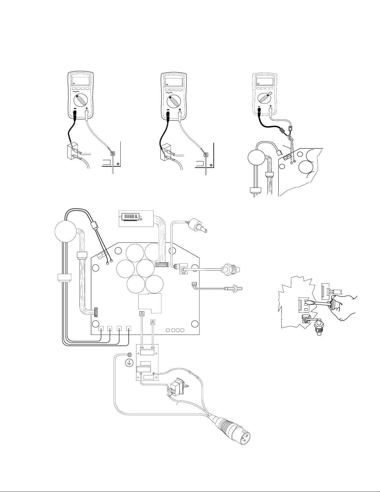
Unit Will Not Run - Steps: 100-120 VAC NA Units
On/Off
Switch
110-120 AC
-
Power Cord
Thermal
Switch
Motor
V
-
Black
STEP 1:
Plug power cord in
and turn switch ON.
Connect wires to
control board and
ON/OFF switch. Turn
meter to AC volts.
Black
+
White
Control
Board
On/Off
Switch
Digital Display
110-120 AC
V
-
-
Black
Black
Power Cord
STEP 2:
Plug power cord in
and turn switch ON.
Connect wires to
control board and
ON/OFF switch. Turn
meter to AC volts.
+
White
Control
Board
Potentiometer
Pressure
Transducer
100k ohm
-
Thermal
Switch
Motor
STEP 3:
Check motor thermistor.
Unplug yellow wires. Meter
should read 6.2k ohms.
NOTE: Motor should be cool
during reading.
+
-
Ye l l o w
Control
Board
STEP 4:
Plug power cord in and
turn switch ON. Disconnect
potentiometer. Use
nonmagnetic screwdriver
to short pins.
Motor
Leads
Motor
Sensor
Leads
Green/Ground
Control
Board
Black
Green/Ground
White
Black
Prime/Fill Tool
Reed switch
20A/15A
Switch
ti14889a
Control
Board
Black
26 3A0245A
Unit Will Not Run - Steps: 100-120 VAC UK
Troubleshooting
Black
On/Off
Switch
Motor
110-120 AC
V
-
Brown +
Thermal
Switch
STEP 1:
Plug power cord in
and turn switch ON.
Connect wires to
control board and
ON/OFF switch. Turn
meter to AC volts.
White
Brown
Blue
On/Off
Switch
Digital Display
Black
110-120 AC
V
-
Brown +
STEP 2:
Plug power cord in
and turn switch ON.
Connect wires to
control board and
ON/OFF switch. Turn
meter to AC volts.
White
Brown
Blue
Potentiometer
Black
Pressure
Transducer
100k ohm
-
Thermal
Switch
Motor
STEP 3:
Check motor thermistor.
Unplug yellow wires. Meter
should read 6.2k ohms.
NOTE: Motor should be cool
during reading.
+
-
Ye l l o w
Control
Board
STEP 4:
Plug power cord in and
turn switch ON. Disconnect
potentiometer. Use
nonmagnetic screwdriver
to short pins.
Motor
Leads
Motor
Sensor
Leads
Green/Ground
Control
Board
Brown
Green/Ground
Blue
Brown
Blue
ti15686a
Prime/Fill Tool
Reed switch
Control
Board
Black
3A0245A 27

Troubleshooting
Unit Will Not Run - Steps: 220-240 VAC Units
Brown
On/Off
Switch
Brown
Black
Motor
220-240 VAC
V
-
Blue
Thermal
Switch
STEP 1:
Plug power cord in
and turn switch ON.
Connect wires to
ON/OFF switch. Turn
meter to AC volts.
White
Blue
Digital Display
Brown
On/Off
Switch
Brown
Black
220-240 VAC
V
-
White
Blue
Blue
Potentiometer
STEP 2:
Plug power cord in
and turn switch ON.
Connect wires to
ON/OFF switch. Turn
meter to AC volts.
Pressure
Transducer
Black
100k ohm
-
Thermal
Switch
Motor
STEP 3:
Check motor thermistor.
Unplug yellow wires. Meter
should read 6.2k ohms.
NOTE: Motor should be cool
during reading.
+
-
Yellow
Control
Board
STEP 4:
Plug power cord in and
turn switch ON. Disconnect
potentiometer. Use
nonmagnetic screwdriver
to short pins.
Motor
Leads
Motor
Sensor
Leads
Green/Ground
Blue
Control
Board
Black
Blue
Brown
Brown +
ti15685a
Prime/Fill Tool
Reed switch
Blue
Control
Board
Black
28 3A0245A

Technical Data (Unit)
Technical Data (Unit)
Power requirements:
Models 257100, 262288
Models 258906, 262300
Model 258907
Motor HP (W) 2.5 (1864)
Maximum fluid working pressure 2500 psi (17.2 MPa, 172 bar)
Hopper capacity 25 gallons (95 liters)
Maximum delivery with texture
material
Maximum hose length 150 ft of 1/2 in. hose plus 15 ft of 1/4 in. hose
Fluid outlet size 1/2 in. NPT female swivel
Dimensions
Length 40 to 55 in. (102 cm to 140 cm) with handle
Width 22 in. (56 cm)
Height 31 in. (79 cm)
Weight (with hoses and applicator) 196 lb (89 kg)
Wetted parts Buna-N, aluminum, brass, polyethylene, neoprene, stainless steel,
Sound data for drywall feed pump
Sound pressure level * 80.0 dB(A)
Sound power level † 94.7 dB(A)
* Measured while dispensing at 1 m
† Measured per ISO-3744
100-120 VAC, 60 Hz, 15/20A
220-240 VAC, 50 Hz, 10A
100-120 VAC, 50/60 Hz, 15A
Up to 1.5 gpm (5.7 lpm) - varies depending on material
nickel-plated carbon steel, fluoroelastomer, nickel-plated iron, wool
felt, tungsten carbide, PTFE, nylon, zinc-plated carbon steel, paper,
PVC, UHMWPE, leather, rubber
Technical Data (Pump)
Maximum working pressure 2500 psi (172 bar, 17.2 MPa)
Fluid outlet size 1/2 npt(f)
3A0245A 29

Notes
Notes
30 3A0245A

Graco Standard Warranty
Graco Standard Warranty
Graco warrants all equipment referenced in this document which is manufactured by Graco and bearing its name to be free from defects in
material and workmanship on the date of sale to the original purchaser for use. With the exception of any special, extended, or limited warranty
published by Graco, Graco will, for a period of twelve months from the date of sale, repair or replace any part of the equipment determined by
Graco to be defective. This warranty applies only when the equipment is installed, operated and maintained in accordance with Graco’s written
recommendations.
This warranty does not cover, and Graco shall not be liable for general wear and tear, or any malfunction, damage or wear caused by faulty
installation, misapplication, abrasion, corrosion, inadequate or improper maintenance, negligence, accident, tampering, or substitution of
non-Graco component parts. Nor shall Graco be liable for malfunction, damage or wear caused by the incompatibility of Graco equipment with
structures, accessories, equipment or materials not supplied by Graco, or the improper design, manufacture, installation, operation or
maintenance of structures, accessories, equipment or materials not supplied by Graco.
This warranty is conditioned upon the prepaid return of the equipment claimed to be defective to an authorized Graco distributor for verification of
the claimed defect. If the claimed defect is verified, Graco will repair or replace free of charge any defective parts. The equipment will be returned
to the original purchaser transportation prepaid. If inspection of the equipment does not disclose any defect in material or workmanship, repairs will
be made at a reasonable charge, which charges may include the costs of parts, labor, and transportation.
THIS WARRANTY IS EXCLUSIVE, AND IS IN LIEU OF ANY OTHER WARRANTIES, EXPRESS OR IMPLIED, INCLUDING BUT NOT LIMITED
TO WARRANTY OF MERCHANTABILITY OR WARRANTY OF FITNESS FOR A PARTICULAR PURPOSE.
Graco’s sole obligation and buyer’s sole remedy for any breach of warranty shall be as set forth above. The buyer agrees that no other remedy
(including, but not limited to, incidental or consequential damages for lost profits, lost sales, injury to person or property, or any other incidental or
consequential loss) shall be available. Any action for breach of warranty must be brought within two (2) years of the date of sale.
GRACO MAKES NO WARRANTY, AND DISCLAIMS ALL IMPLIED WARRANTIES OF MERCHANTABILITY AND FITNESS FOR A
PARTICULAR PURPOSE, IN CONNECTION WITH ACCESSORIES, EQUIPMENT, MATERIALS OR COMPONENTS SOLD BUT NOT
MANUFACTURED BY GRACO. These items sold, but not manufactured by Graco (such as electric motors, switches, hose, etc.), are subject to
the warranty, if any, of their manufacturer. Graco will provide purchaser with reasonable assistance in making any claim for breach of these
warranties.
In no event will Graco be liable for indirect, incidental, special or consequential damages resulting from Graco supplying equipment hereunder, or
the furnishing, performance, or use of any products or other goods sold hereto, whether due to a breach of contract, breach of warranty, the
negligence of Graco, or otherwise.
FOR GRACO CANADA CUSTOMERS
The Parties acknowledge that they have required that the present document, as well as all documents, notices and legal proceedings entered into,
given or instituted pursuant hereto or relating directly or indirectly hereto, be drawn up in English. Les parties reconnaissent avoir convenu que la
rédaction du présente document sera en Anglais, ainsi que tous documents, avis et procédures judiciaires exécutés, donnés ou intentés, à la suite
de ou en rapport, directement ou indirectement, avec les procédures concernées.
Graco Information
For the latest information about Graco products, visit www.graco.com.
TO PLACE AN ORDER, contact your Graco distributor or call 1-800-690-2894 to identify the nearest distributor.
3A0245A 31

All written and visual data contained in this document reflects the latest product information available at the time of publication.
Graco reserves the right to make changes at any time without notice.
Original instructions. This manual contains English. MM 3A0245
Graco Headquarters: Minneapolis
International Offices: Belgium, China, Japan, Korea
GRACO INC. P.O. BOX 1441 MINNEAPOLIS, MN 55440-1441
Copyright 2010, Graco Inc. is registered to ISO 9001
www.graco.com
 Loading...