

Page 1
1
10/2015 EN
ENGLISH
PRSU/M2SI
Multifunctional Downstream Device
0266691
Before installing, operating or maintaining the device, read and
understand this manual.
DANGER
ATTENTION
Dangerous tension.
Danger to life or serious injury.
Disconnect the system and device from the power before
starting work.
A secure device function is only guaranteed with certified
components!
Hints
The products described here are designed to perform safety-related
functions as part of an overall plant or machine. A complete safetyrelated system usually contains sensors, evaluation units, signaling
devices and concepts for safe shutdowns. It is the responsibility of the
manufacturer of a system or machine to ensure the correct overall
function. Tapeswitch is unable to guarantee all the features of a
complete system or machine that was not designed by Tapeswitch. The
overall concept of the controller in which the device is integrated must be
validated by the user. Tapeswitch also assumes no liability for
recommendations that are given or implied by the following description.
Due to the following description, no new warranty, warranty or liability
claims beyond the general tapeswitch delivery conditions can be derived.
Safety Regulations
-
-
The device may only be installed and commissioned by
knowledgeable persons who are familiar with this operating manual
and with the applicable regulations on occupational safety and
accident prevention.
Observe the VDE and local regulations, especially with regard to
protective measures.
- Opening the case or unauthorized modifications will invalidate any
warranty.
- Mount the device in a control cabinet with degree of protection IP 54 or
better; Dust and moisture can otherwise lead to impairments of the
functions.
- Provide sufficient protective wiring at all output contacts for capacitive
and inductive loads.
- The safety function must be triggered during commissioning.
If used as directed and in accordance with this manual, no residual risks
are known. Failure to do so may result in personal injury and property
damage.
The PRSU / M2SI is used for the safety-related release and interruption of
a safety circuit. It can be used to protect people and machinery in
applications with emergency stop pushbuttons, safety gates, self-test (type
4) photocells in accordance with IEC / EN 61 496-1, two-hand switches for
metalworking presses, and other working machines with dangerous
closing movements (Type III C according to EN 574) and for safety-related
safety mats, safety edges and band switches.
Intended Use
Device Properties
Your advantages
• two independent safety functions adjustable
out:
- Safety mat / strip, band switch
- photocell
- Emergency stop switch
- Safety gate
- two-hand control
- Antivalent switch
• only one device type, two safety functions at the same time
• manual or automatic start
Characteristics
• complies
- Performance Level (PL) e and Category 4 according to EN ISO
13849-1: 2008
- SIL claim limit (SIL CL) 3 according to IEC / EN 62061
- Safety Integrity Level (SIL) 3 according to IEC / EN 61508 and IEC /
EN 61511
• according to EN 50156-1 for combustion plants
• Line fault detection on the ON button
• Activation via on-button or automatic on-function
• with or without cross-circuit detection
• 2-channel design
• positively driven output contacts
• Output: 2 NO contacts per safety function
• 1 semiconductor output per safety function
• LED indic
ators operating voltage, safety function 1, 2 and error
• Device connections: pluggable terminal blocks with screw terminals
Safety Instructions
ATTENTION - AUTOMATIC START!
According to IEC / EN 60 204-1 point 9.2.5.4.2, no automatic start must
be made after stopping in an emergency. Therefore, in the modes with
automatic start, a higher-level control must prevent an automatic start
after an emergency stop.
Terminals
Terminal Designation
Signalbeschreibung
A1 + DC24V
A2 0V
13, 14, 23, 24,
43, 44, 53, 54
Normally open for release
circuit
38, 68
Semiconductor monitoring output
GND
Reference potential for
semiconductor signal outputs
S11, S21, S31, S41
control outputs
S12, S22, S32, S42,
ST1, ST2, RES
control outputs
ORIGINAL
All information in this manual corresponds to the technical state at the time of issue. We reserve
the right to make technical improvements and changes at any time.
Operating Manual
E-mail: [email protected] • Web: www.tapeswitch.com Phone: 631-630-0442 • Toll Free: 800-234-8273
Page 2
2
10/2015 EN
Operating instructions ENGLISH
Before installing, operating or maintaining this device, these instructions
must be carefully read and understood.
DANGER
CAUTION
Dangerous voltage.
Electric shock will result in death or serious injury.
Disconnect all power supplies before servicing equipment.
Safe operation of the device is only guaranteed when using certified
components!
Important Notes
The product hereby described was developed to perform safety functions
as a part of a whole installation or machine. A complete safety system
normally includes sensors, evaluation units, signals and logical modules
for safe disconnections. The manufacturer of the installation or machine is
responsible for ensuring proper functioning of the whole system. Tapeswitch
cannot guarantee all the specifications of an installation or machine that
was not designed by Tapeswitch. The total concept of the control system
into which the device is integrated must be validated by the user. Tapeswitch
also takes over no liability for recommendations which are given or implied
in the following description. The following description implies no modification
of the general Tapeswitch terms of delivery, warranty or liability claims.
Safety Regulations
- This device must be installed and operated by trained staff who are
familiar with these instructions and with the current regulations for safety
at work and accident prevention.
- Pay attention to applicable local regulations, especially regarding safety
measures.
- Opening the device or implementing unauthorized changes voids any
warranty
- The unit should be panel mounted in an enclosure rated at IP 54 or
superior. Dust and dampness may lead to malfunction.
- Adequate fuse protection must be provided on all output contacts with
capacitive and inductive loads.
- The safety function must be triggered during commissioning
When used in accordance with its intended purpose and following these
operating instructions, this device presents no known residual risks. Nonobservance may lead to personal injuries and damages to property.
The PRSU/M2SI is used to enable and interrupt a safety circuit in a safe
way. It can be used to protect people and machines in applications with
e-stop buttons, safety gates, light curtains with selftesting (Type 4) acc. to
IEC/EN 61 496-1, 2-hand controls for presses as well as other production
machinery with dangerous closing action (Type III C to EN 574) and for
safety mats, safety edges and tape switches.
Designated Use
Main Features
Your Advantage
•
2 independent, separately adjustable safety functions:
- Safety mat / Safety edge / Tapeswitch
- Light curtain
- E-Stop
- Safety gate
- Two-hand control
- Exclusive or contacts
• Only one device, two safety functions at the same time
•
Manual or auto start
Features
• According to
- Performance Level (PL) e and category 4 to EN ISO 13849-1: 2008
- SIL Claimed Level (SIL CL) 3 to IEC/EN 62061
- Safety Integrity Level (SIL) 3 to IEC/EN 61508 and IEC/EN 61511
• Acc. to EN 50156-1 for furnaces
• Line fault detection on On-button:
• Manual restart or automatic restart
• With or without cross fault monitoring
• 2-channel
• Forcibly guided output contacts
• Output: 2 NO contacts per safety function
• 1 semiconductor output per safety function
• LED indicator for operation, safety function 1, 2 and failure
• Removable terminal strips: plug in screw terminals
Safety Notes
ATTENTION - AUTOMATIC START!
According to IEC/EN 60 204-1 part 9.2.5.4.2 and 10.8.3 it
is not allowed
to restart automatically after emergency stop. Therefore the machine
control has to disable the automatic start after emergency stop.
Connection Terminals
0266691
Terminal designation Signal designation
A1 + DC 24 V
A2 0 V
13, 14, 23, 24,
43, 44, 53, 54
Forcibly guided NO contacts for
release circuit
38, 68 Semiconductor monitoring output
GND Reference potential for
Semiconductor monitoring output
S11, S21, S31, S41 control output
S12, S22, S32, S42,
ST1, ST2, RES
control input
PRSU/M2SI
Multifunctional Control Unit
ORIGINAL
All technical data in this manual relate to the state at the moment of edition. We reserve the right
for technical improvements and changes at any time.
Page 3
3
10/2015 EN
Practical Notes
Operation mode
With the potentiometer on the front plate the operartion mode can be
adjustet. The adjustment must be required before energizied. Adjustment
during energization is not allowed.
Only an automatic start at safety function two-hand control (3) is possible.
Start Fkt. 1 Fkt. 2
1 MANUAL MANUAL
2 MANUAL AUTO
3 AUTO HAND
4 AUTO AUTO
5
MANUAL with common
button
Line fault detection e.g. monitoring of ON-button
If the On-button pressed more than 3 s the adequate output contacts of the
safety function can't be switch. The output contacts can be energized when
the On-button pressed again (0.1 s < t
ON
< 3 s).
A line fault is detected if the On-button more than 10 s is actuated. The
output contacts of the adeauate safety function can only be energized with
a reset or re-start with on an off switching of power supply.
ATTENTION - AUTOMATIC START!
According to IEC/EN 60 204-1 part 9.2.5.4.2 and 10.8.3 it
is
not allowed to restart automatically after emergency stop.
Therefore the machine control has to disable the automatic
start after emergency stop.
Reset and external failures:
The reset input is used to reset external failures (application failures or
removable external failures as e.g. a line fault on reset button). If the reset
signal is connected to the input for more than 3 sec the unit unit makes a
reset. A new reset is only possible when the reset signal had been switched
off temporarily.
If an external failure occurs because both input channels of a safety function
did not switch on or off within the simultanious time, a reset is only possible
if both channels are switched to off state after removing failure cause.
If an external failure occurs in only one safety function, only this function
will be disconnected. The second safety function still continuous to work.
Function setting
The variants with selectable safety functions have 2 potentiometers Fkt.1
and Fkt.2 to select the required function. The following functions are possible:
Fct. 1 / Fct. 2 Safety function
1 E-Stop
cross fault detection
2 Safety gate
3 Two-hand control
4 Safety mat / Safety edge
5 Exclusive or contacts
6 E-Stop
without
cross fault detection
7 Safety gate
8 Light curtain
Indicators
green LED ON: on, when supply connected
red LED ERR: on, at internal error
flashes at external error
green LED K1/K2: on, when relay K1 and K2 energized
(safety function 1)
flashes at external errors of
safety function 1
green LED K3/K4: on, when relay K3 and K4 energized
(safety function 2)
flashes at external errors of
safety function 2
Operating Potentiometer
Poti "Start" Adjustment of operating mode
Manual- or auto start for Fkt.1 and Fkt. 2.
Poti "Fkt.1" Adjustment of safety function 1
Poti "Fkt.2" Adjustment of safety function 2
Fault Indication by Flashing Code
simultaneity
error
Potentiometer or
adjustment failure
line fault across
start button
Cross fault or
wiring fault
M10697_a
Page 4
4
10/2015 EN
Function diagram
Technical Data
Technical Data
Input
Nominal voltage UN: DC 24 V
Voltage range: 0.8 ... 1.1 U
N
Nominal consumption: typ. 3.2 W
Short-circuit protection: Internal PTC
Overvoltage protection: Internal VDR
Duty-cycle ON button: 0.1 s < t
EIN
< 3 s
Duty-cycle Reset button: > 3 s
Safety function
Safety mat / safety edge / Tapeswitch (4)
max. permitted
safety edge contact resistance: 1000 Ω
switching current at short circuit: typ. 15 mA at U
N
Light curtains (8)
control current via S12, S22
e.g. S32, S42: typ. 8 mA at U
N
Min. voltage on terminals
S12, S22 e.g. S32, S42
when relay activated: DC 10 V
Output
Contacts 2 NO contacts per safety function
The NO contacts can be used for safe braking.
Thermal current Strom Ith: max. 8 A
Safety function
E-Stop (1) (6), Safety gate (2) (7),
Exclusive or contacts (5)
Start up at U
N
: < 65 ms
Release delay at UN and
disconnecting the supply: < 40 ms
Release delay at UN and
disconnecting S12,S22 or
S32, S42: < 60 ms
Two-hand control (3)
Start up at UN: < 110 ms
Release delay at UN and
disconnecting the supply:
< 40 ms
Release delay at UN and
disconnecting S12,S22 or
S32, S42: < 60 ms
simultaneity demand: max. 0,5 s
Safety mat (4) / Safety Edge / Tapeswitch
Start up at UN: < 85 ms
Release delay at UN and
disconnecting the supply: < 40 ms
Release delay at UN and
disconnecting S12,S22 or
S32, S42: < 60 ms
Light curtains (8)
Start up at UN: < 35 ms
Release delay at UN and
disconnecting the supply: < 40 ms
Release delay at UN and
disconnecting S12,S22 or
S32, S42: < 25 ms
t
diff
: max. time delay for simultaneity demand
dependent on selected safety function
Safety mat, Sensing Edge, Tapeswitch, E-Stop, Safety Gatet
diff
= max. 3s
Light curtain t
diff
= max. 1s
Two-hand control t
diff
= max. 0,5s
other times on request
tOn: max. actuation time of start button
Standard tOn: max. 3s
other times on request
Page 5

5
10/2015 EN
Troubleshooting
Failure Potential cause
LED "ON" does not light up - Power supply A1+/A2
not connected
LED "ERR" flashes
in relation 1:1
- Under- or overvoltage
(check power supply A1+/A2)
LED "ERR" flashes
in relation 4:1
- external failure (see flashing code)
LED "ERR"
continuously on
- system error
(if cannot be removed after restart
unit must be replaced)
Maintenance and Repairs
- The device contains no parts that require maintenance.
- In case of failure, do not open the device but send it to manufacturer
for repair.
Technical Data
Switching capacity
to AC 15
NO contacts: 3 A / AC 230 V IEC/EN 60 947-5-1
to DC 13
NO contacts: 2 A / DC 24 V IEC/EN 60 947-5-1
Electrical life
at 5 A, AC 230 V cos j = 1: > 1.5 x 10⁵ switching cycles
Permissible operating frequency
1. safety function: max. 1800 switching cycles / h
2. safety function: max. 360 switching cycles / h
Short circuit strength
max. fuse rating: 6 A gL IEC/EN 60 947-5-1
Mechanical life: 10 x 106 switching cycles
Semiconductor monitoring output
(not safety): 1 per safety function
max. 50 mA DC 24 V, plus switching
General Data
Nominal operating mode: continuous operation
Temperature range
Operation: - 15 ... + 55 °C
Storage: - 25 ... + 85 °C
Altitude:
< 2.000 m
Clearance and creepage distance
rated impuls voltage /
pollution degree: 4 kV / 2 IEC 60 664-1
EMC
Electrostatic discharge (ESD): 8 kV (air) IEC/EN 61 000-4-2
HF irradiation: 10 V / m IEC/EN 61 000-4-3
Fast transients: 2 kV IEC/EN 61 000-4-4
Surge voltage
between
wires for power supply: 1 kV IEC/EN 61 000-4-5
between wire and ground: 2 kV IEC/EN 61 000-4-5
HF-wire guided: 10 V EN 61 000-4-6
Interference suppression: Limit value class B EN 55 011
Degree of protection
Housing: IP 40 IEC/EN 60 529
Terminals: IP 20 IEC/EN 60 529
Housing: thermoplastic with VO behaviour
according to UL subj. 94
Vibration resistance: Amplitude 0,35 mm
Frequency 10 ... 55 Hz, IEC/EN 60 068-2-6
Klimate resistance: 15 / 055 / 04 IEC/EN 60 068-1
Terminal designation: EN 50 005
Wire connection: DIN 46 228-1/-2/-3/-4
Wire fixing: captive slotted screw
Mounting: DIN rail IEC/EN 60 715
Weight: approx. 275 g
UL-Data
The safety functions were not evaluated by UL. Listing is accomplished according to requirements of Standard UL 508, “general use
applications”
Switching capacity:
Ambient temperature 55°C Pilot duty B300, Q300
5A 250Vac Resistive or G.P.
5A 24Vdc Resistive
Ambient temperature 40°C: Pilot duty B300, Q300
8A 250Vac Resistive or G.P.
8A 24Vdc G.P.
Wire connection:: 60°C / 75°C copper conductors only
Terminal: AWG 28 - 12 Sol/Str Torque 0.5 Nm
Page 6
6
10/2015 EN
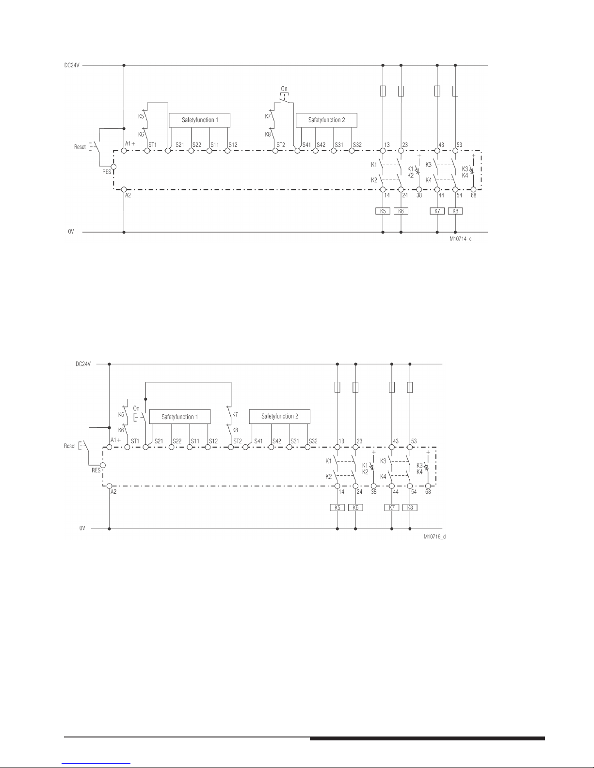
Operating mode: 3 (Fkt1=AUTO ; Fkt2=MANUAL)
Safety function 1: see page
7, Auto-Start
Safety function 2: see page 7, Manual-Start
Operating mode: 5 (MANUAL with common button)
Safety function 1: see page 7, Manual-start with common button
Safety function 2: see page 7, Manual-start with common button
Application examples with safety function
PRSU/M2SI
PRSU/M2SI
Page 7
7
10/2015 EN
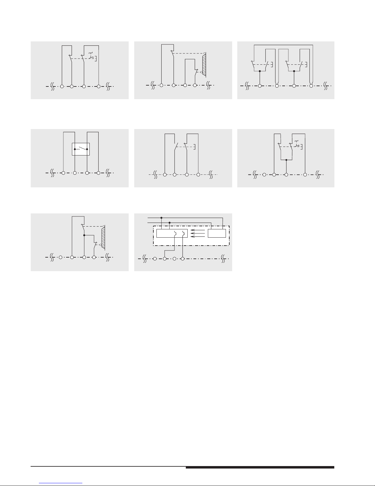
Application examples with safety function 1
Application examples with safety function 2
The safety function 2 is connected as well as safety function 1, but S11 S31, S12 S32, S21 S41 and S22
S42.
S22 S11 S12
M10757
NotAus
S21
S21 S22 S11 S12
Schiebeschutztür
geschlossen
M10756
S1
S2
S22S21 S11 S12
M10750
Fct.: E-stop (1),
with cross fault detection
SIL 3, PL e, Cat. 4
Fct.: Safety gate (2),
with cross fault detection
SIL 3, PL e, Cat. 4
Fct.: Two-hand control (3),
with cross fault detection
SIL 3, PL e, Cat. 4
Type III C to EN 574
S21 S22 S11 S12
Schaltleiste
M10754
S22 S11
S12S12
S1
M11124
S21 S22 S11 S12
M10753
NotAus
S21
Fct.: Safety mat / Safety edge / Tapeswitch (4), with cross fault detection
SIL 3, PL e, Cat. 4
Fct.: Exclusive or contacts (5),
with cross fault detection
SIL 3, PL e, Cat. 4
Fct.: E-Stop (6),
without cross fault detection
SIL 3, PL e, Cat. 4
1)
S21 S22 S11 S12
Schiebeschutztür
geschlossen
M10752
OSSD1 OSSD2
S22
S21
S11 S12
Sender
Empfänger
DC
24V
0V
M10751
Fct.: Safety gate (7),
without cross fault detection
SIL 3, PL e, Cat. 4
1)
Fct.: Light curtain (8),
without cross fault detection
SIL 3, PL e, Cat. 4
2)
1
) To achieve the stated safety classification the wiring has to be done with crossfault monitoring.
2
) To achieve the stated safety classification light curtains with selftest (type 4) according to IEC/EN 61496-1 have to be used.
Page 8
8
10/2015 EN
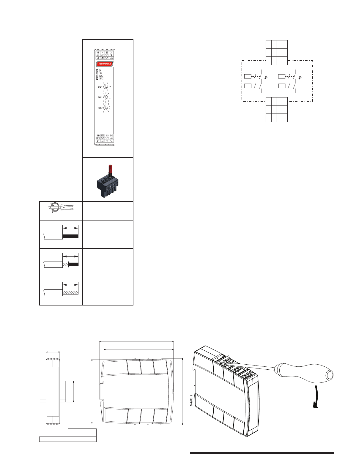
Circuit diagram
S12
A2
14
44
GND
S32
S11
A1+
13
43
RES
S31
S21
ST1
23
53
ST2
S41
S22
38
24
54
68
S42
M10501_a
13 43
K1 K3
K2 K4
23 53
14 44
24 54
K3/K4K1/K2
++
6838
Labeling and connections
M10707
M
4
2
8
8
_
a
DIN 5264-A; 0,6 x 3,5
0,5 Nm
5 LB. IN
M10248
A
A = 7 mm
1 x 0,2 ... 2,5 mm
2
1 x AWG 24 to 12
2 x 0,2 ... 1,0 mm
2
2 x AWG 24 to 18
M10249
A
A = 7 mm
1 x 0,25 ... 2,5 mm
2
1 x AWG 24 to 12
2 x 0,25 ... 1,0 mm
2
2 x AWG 24 to 18
M10250
A
A = 7 mm
1 x 0,2 ... 2,5 mm
2
1 x AWG 24 to 12
2 x 0,2 ... 1,5 mm
2
2 x AWG 24 to 16
Dimensions (dimensions in mm)
A B
PRSU/M2SI 110
± 1
22,5
M
4
3
4
5
_
a
M
4
3
4
5
_
a
3
5
115,3
-
0
0,7
+
122,6
-
0
0,7
+
B
A
1
0
6
,9
Mounting / disassembly of the terminal blocks
Page 9
9
10/2015 EN
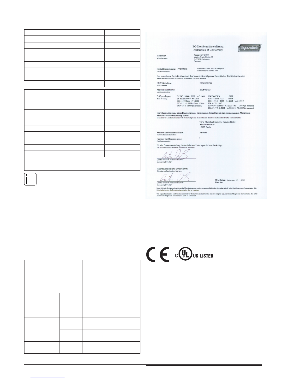
CE-Declaration of Conformity
EN ISO 13849-1:
Category: 4
PL: e
MTTF
d
: 134,5 a (year)
DC
avg
: 99,0 %
d
op
: 365 d/a (days/year)
h
op
: 24 h/d (hours/day)
t
cycle
: 3600 s/cycle
1 /h (hour)
IEC/EN 62061
IEC/EN 61508
IEC/EN 61511:
SIL CL: 3 IEC/EN 62061
SIL: 3
IEC/EN 61508 /
IEC/EN 61511
HFT
*)
: 1
DC
avg
: 99,0 %
SFF: 99,6 %
PFH
D
: 3,89E-10 h
-1
PFD: 3,27E-05
T
1
20 a (year)
*)
HFT = Hardware failure tolerance
Safety related data
nfo
The values stated above are valid for the standard type. Safety data for
other variants are available on request.
The safety relevant data of the complete system has to be determined
by the manufacturer of the system.
Approvals and Markings
Demand to our devic
e based on the
evaluated neccessary safety level of
the application.
In
tervall for cyclic test of the
safety function
EN ISO 13849-1
PL e with
Cat. 3
or Cat. 4
once per month
PL d with
Cat. 3
once per year
IEC/EN 62061,
IEC/EN 61508
SIL CL 3,
SIL 3
with HFT = 1
once per month
SIL CL 2,
SIL 2
with HFT = 1
once per year
EN 61511, EN 50156-1
SIL 3 once per year
TÜV
Baumuster
geprüft
Tapeswitch Corporation
e-mail: sales
@tapeswitch.com •
web: http://www.tapeswitch.
com
Phone: 631-630-0442 Toll Free: 800-234-8273
 Loading...