


Release 7/2009 Ver. 1.0 Technical Manual: GS-120 Light Curtain Systems
GS-120 Photo-Electric Light Curtain Systems
Technical Manual
WARNING
Tapeswitch photo-electric safety systems are intended to protect operators working at or near
dangerous machinery. They can only perform this function if they are correctly fitted to a
suitable machine. It is essential that the full contents of this manual and all the international
documents referred to herein are fully understood before any attempt at installation is made.
If in doubt, contact Tapeswitch Corporation.
IMPORTANT
This manual must accompany the product throughout its working life. Those persons
responsible for the product must ensure that all persons involved in the installation,
commissioning, operation, maintenance and servicing of the product have access to all the
information supplied by the manufacturers of the machine and its safety system.

Release 7/2009 Ver. 1.0 Technical Manual: GS-120 Light Curtain Systems
TABLE OF CONTENTS
1.0 GENERAL
1.1 INTRODUCTION 4
1.2 PRODUCT Range
1.2.1 General 4
1.2.2 Detection Capability 5
1.2.3 Protected Heights
1.2.4 Accessories 5
1.2.4.1 Mirror Units 5
1.2.4.2 Mounting Stands 7
5
1.3 ORDERING INFORMATION
1.32 GS-120 Multi-Beam Order Code 8
1.3.3 Cable Options 9
1.3.4 Interface and Programming Units 9
1.3.1 GS-120 Light Curtain Order Code 8
4
7
2.0 TECHNICAL DESCRIPTION
9
2.1 CURTAIN 9
2.2 COMMUNICATIONS
2.3 TEST INPUT
2.4 INDICATORS
2.4.1 LED Option 11
2.4.2 Diagnostic Option 12
3.0 INSTALLATION
10
10
11
13
3.1 GENERAL 13
3.2 MECHANICAL INSTALLATION
13
3.2.1 General Considerations 13
3.2.1.1 Multi-Sided Guarding 15
3.2.2 Curtain Dimensions 16
3.2.2.1 GS-120 Basic Syste m 16
3.2.2.2 GS-120 Multi-Beam System 17
3.2.2.3 GS-120 Cascaded System 18
3.2.3 Separation Distance 19
3.2.3.1 Normal Approach 19
3.2.3.2 Parallel Approach 21
3.2.3.3 Angled Approach 22
3.2.3.4 Approach to ‘L’ Installation 22
3.2.4 Optical Alignment 23
3.2.5 Reflective Surfaces 23
3.2.6 Systems in Close Proximity 24
3.2.7 Mounting Brackets 24
3.3 ELECTRICAL INTERFACE, OPERATION, AND INSTALLATION 27
3.3.1 General 27
3.3.2 Emitter Unit 27
3.3.2.1 General 27
3.3.2.2. Test Input 28
3.3.3 Receiver Unit 28
3.3.3.1 General 28
3.3.3.2 PNP Version 29
3.3.3.3 SSR Version 30
3.3.4 Interfacing to a Machine 31
3.34.1 PNP Version Manual Reset 31
3.34.2 PNP Version Auto Reset 32
3.34.3 SSR Version 33
3.4 INITIAL CHECKING AND ALIGNMENT 34
4.0 INTERFACE AND AUXILIARY UNITS 35
4.1 GENERAL 35
4.1.2 Special Interfacing Considerations 36
4.1.1 Methods of Interfacing 35
TAPESWITCH CORPORATION Phone: 631-630-0442
100 Schmitt Boulevard
Farmingdale, New York 11735 www.tapeswitch.com
2 Fax: 631-630-0454

Release 7/2009 Ver. 1.0 Technical Manual: GS-120 Light Curtain Systems
4.1.2.1 PNP Version Manual Reset 36
4.1.2.2 PNP Version Auto Reset 36
4.1.2.3 SSR Version 36
4.1.3 Connections to an AS-i System 37
5.0 PERIODIC CHECKING, SERVICING, AND MAINTENANCE 38
5.1 PERIODIC CHECKING 38
5.1.1 Commissioning Checks 38
5.1.2 6 or 12 Month Periodic Checks 38
5.1.3 Daily/Setting Examination 39
5.1.4 Checking Detection Capability 39
5.1.4.1 GS-120 System 39
5.1.4.2 GS-120 Multi-Beam System 40
5.2 SERVICING 41
5.3 MAINTENANCE
6.0 TECHNICAL SPECIFICATIONS (GS-120Series Emitter & Receiver) 42
APPENDIX A: BSRSA INTERFACE UNIT
APPENDIX B: BSRUA-2 INTERFACE UNIT
APPENDIX C: SRUB INTERFACE UNIT
APPENDIX D: SRUS INTERFACE UNIT
APPENDIX E: C6 MULTIFUNCTION INTERFACE CONTROLLER
APPENDIX F: GDC-1 24 VDC POWER SUPPLY
APPENDIX G: LAT LAS ER A LI G N ME NT TOOL
41
43
49
57
63
67
68
69
TAPESWITCH CORPORATION Phone: 631-630-0442
100 Schmitt Boulevard
Farmingdale, New York 11735 www.tapeswitch.com
3 Fax: 631-630-0454

Release 7/2009 Ver. 1.0 Technical Manual: GS-120 Light Curtain Systems
1.0 GENERAL
1.1 INTRODUCTION
Tapeswitch GS-120 light curtains are through-beam
photo-electric machine gu arding devices, designed to
protect operators working at or near dangerous
machinery. They m eet the requirements for EN61496
Type 2 light curtains and Category 3 safety control units
as defined in EN954-1.
When correctly installed on a suitable machine, the
system will detect a person (or part of a person) ente ring
a dangerous area in the vicinity of the machine, and will
signal the dangerous motion to cease before that
person can reach a position where injury could occur.
Tapeswitch GS-120 light curtains use infra-red
technology. A curtain of infra-red light is projected
across the dangerous area. Intrusion into this curtain by
a person or part of a person will be detected by the
system. This will cause safety output signals to be
generated which will stop t he dangero us m otion of the
machine.
WARNING
The information in this manual relates to the
use of the basic GS-120 light c urtain, to provi de
a basic safety switching device.
In some applications, a GS-120 light curtain
may be used together with other Tapeswitch
equipment to provide additional functions and
features. The additional information nec essary
for the correct use of a GS-120 light curtain
when used with other Tapeswitch equipme nt is
provided within this manual.
In such cases, some installation parameters,
notably the mounting position of the light
curtain in relation to the dangerous part of the
machine, can be affected and close attention
must be paid to all the information supplied
with all equipment.
INTERNATIONAL CONSIDERATION: The heritage of
the Tapeswitch GS-120 system is strongly grounded in
international commerce and standards. They were
developed by Tapeswitch Ltd., of Chorley, England.
Both Tapeswitch Ltd . and Tapes witch U.S. are p art of
Indel Corporation, a private U.S industrial group . The
GS-120 product line was d eve lo ped t o meet published
and proposed safet y standards for the United States,
Germany, England, Finland, and Sweden, as well as the
common market unified standard. GS-120 systems are
manufactured both in Eng land and the United States.
Tapeswitch GS-120 products have been independently
third party tested to IEC 61496 by BG, and are certified
to this standard (CE approval/certification). Contact
Tapeswitch for more details.
Tapeswitch can provide additional assistance to
customers wishing to use GS-120 guards in
international applications. Some foreign language
technical manuals are available.
1.2 PRODUCT RANGE
1.2.1 GENERAL
The GS-120 light curtains are available in a rang e of
different protected heights and detection capabilities.
These two parameters are known by many other names
and therefore it ma y be useful to def ine them here, as
they are intended to be us ed in th is m anual. T o make
this clearer it is also necessary to define two further
parameters, detection zone and operating range:
Detection Zone: This is the actual curtain of infra-red
light generated between t he em itter and receiver u nits
within which an appropriately dimensioned obj ect will be
reliably detected and, for the GS-120, can be
considered to be a two dimensio nal, r ectangular plane
(see Figure 1).
Operating Range: One dimension of the detection
zone rectangle is given b y the distance between the
emitter and receiver units . T his is the operat ing ra nge
(see Figure 1).
Protected Height: The other dimension of the
detection zone rectangle is commonly known as the
protected height. The word “height” has been adopted
in the latest standards for this equipment because most
curtains are mounted vertically. The protected height is
often related to, but is not the same as, the length of the
emitter and receiver units (see Figure 1).
TAPESWITCH CORPORATION Phone: 631-630-0442
100 Schmitt Boulevard
Farmingdale, New York 11735 www.tapeswitch.com
4 Fax: 631-630-0454

Release 7/2009 Ver. 1.0 Technical Manual: GS-120 Light Curtain Systems
Figure 1
Detection Capability: This is the minimum dimension
of an opaque object which will be reliably detected
anywhere within the detection zone.
NOTE: The spacing or pitch of the beams or lenses in a
light curtain is not the same as the detection capability.
The detection capability is always greater than the
spacing or pitch. Spacing or pitch should not be used in
the calculation of separation distances (see Figure 2).
1.2.2 DETECTION CAPABILITY
GS-120 light curtains are available with detection
capabilities of 30mm or 70mm.
Figure 2
TAPESWITCH CORPORATION Phone: 631-630-0442
100 Schmitt Boulevard
Farmingdale, New York 11735 www.tapeswitch.com
1.2.3 PROTECTED HEIGHTS
GS-120 light curtains are available with nominal
protected heights as follows:
Detection Capability Nominal protected heights
(in mm and inches)
30mm (1-3/16 in.) 200-300-400-600-800-900 1000-1200-1400-1600 mm
(8-12-16-24-32-36-40-48-56 64-72 inches)
70mm (2-3/4 in.) 600-800-1000-1200-1400 1600-1800 mm
(24-32-40-48-56-64-72
inches)
The minimum separation distance is 0.5 m.
Note:
The actual protected hei ght is 8 mm greater than the
nominal protected height.
1.2.4 ACCESSORIES
1.2.4.1 Mirror Units
A range of mirr or units ar e avail ab le t o en ab le a s ingle
curtain to be used to guard two or three sides of a
machine or to avoid structural obstructions.
The mirror assem bly consists of a high quality silverbacked glass mir ror adhesive ly attach ed to a le ngth of
extruded aluminum . Two pivot brackets ar e bolted to
the aluminum extrusion and can be adjusted anywhere
along the length for mechanical attachment. The actual
length of the mirror is 4 inches (1000mm) larger tha n the
active curtain length to accommodate a wide tolerance
for height alignment. Al l of the necess ary hardwar e is
supplied to facilitate mounting to the mounting/floor
stands. The dimensions of the pivot brackets, extruded
aluminum and overall mirrors are shown below in
millimeters.
5 Fax: 631-630-0454

Release 7/2009 Ver. 1.0 Technical Manual: GS-120 Light Curtain Systems
40mm
6.8mm
40mm
6.8mm
X
Glass Refl ecti v e
Su rface
Overall Length =
Prot ec tive Height + 4"
180° Rotation
in t his Plan e
Pivot Brackets
(180° Rot at io n;
Dis t anc e X is Adjust abl e)
Suppl ied wi t h:
1. 1-40m m x 40m m e xt rusion, 100m m la rger t han
protec t ive heig ht .
2. 1-s il v e r bac k ed mi rror, 100m m larger t han
protec t ive heig ht .
3. 2-pivot joi nts .
4. 2-40m m x 40m m e nd covers .
5. 4-5m m T s l ot nuts .
6. 4-#12 f la t was hers .
7. 4-5mm s pring washers.
8. 4-5m m x 5/ 8 hex bol ts.
Curtain Lengths
Mirror Asse mb ly
Length
P/N
200mm - 8" 300mm - 12" 0960
300mm - 12" 400mm - 16" 0961
400mm - 16" 500mm - 20" 0962
600mm - 24" 700mm - 28" 0963
800mm - 32" 900mm - 36" 0964
900mm - 36" 1000mm - 40" 0965
1000mm - 40" 1100mm - 44" 0966
1200mm - 48" 1300mm - 52" 0967
1400mm - 56" 1500mm - 60" 0968
Pivot Bracket
Extrusion Dimensions
TAPESWITCH CORPORATION Phone: 631-630-0442
100 Schmitt Boulevard
Farmingdale, New York 11735 www.tapeswitch.com
For units greater than 56 inches, custom mirrors are available.
6 Fax: 631-630-0454

Release 7/2009 Ver. 1.0 Technical Manual: GS-120 Light Curtain Systems
3/8" holes
3 lev eling bolts
P/ N 0957
Supplied with:
1. 5 ft. item 40mm X 40mm extrusion
2. 1-base stand.
3. 1-40mm X 40mm end cap.
4. 2-T slot nuts M5.
5. 2-M5 X12mm hex head.
6. 2-M5 spring lock washers.
7. 2-fl at washers 5/5.3mm.
8. 2-5/16 bolts.
9. 3-3/8 24 x 1/2" hex head.
5"
5"
5
4"
4"
1.2.4.2 Mounting Stands
Floor mounting stands are ava ilable f or use where the
guard cannot be mounted directly to the machine.
The mounting stand set includes a floor-mounted base
into which the 5-foot mounting post can be secured.
The floor base is steel and can be permanently mounted
to the floor surface with the pre-drilled mounting holes.
The post is extrud ed aluminum with slots to allow the
light curtain to be positioned anywhere along its length.
The mounting stands are supplied with all of the
necessary hardware to fac ilitate mounting a standard
GS-120 light curtain. Leveling bolts allow for minor
adjustments to the floor stand orientation.
1.3 ORD E RING INFORMATION
Part numbers for the various m odels are s hown in t he
table on the right. To fully specify a model and its
options use an order code as shown in sections 1. 3.1
and 1.3.2 on the following page.
Model Number Part Number
GS-120/8”(208mm)/30 0801
GS-120/12”(308mm)/30 0802
GS-120/16”(408mm)/30 0803
GS-120/24”(608mm)/30 0804
GS-120/32”(808mm)/30 0805
GS-120/36”(908mm)/30 0806
GS-120/40”(1008mm)/30 0807
GS-120/48”(1208mm)/30 0808
GS-120/56”(1408mm)/30 0809
GS-120/64”(1608mm)/30 0810
GS-120/72”(1808mm)/30 0811
GS-120/24”(608mm)/70 0821
GS-120/32”(808mm)/70 0822
GS-120/40”(1008mm)/70 0823
GS-120/48”(1208mm)/70 0824
GS-120/56”(1408mm)/70 0825
GS-120/64”(1608mm)/70 0826
GS-120/72”(1808mm)/70 0827
GS-120-4 0828
GS-120-3 0829
GS-120-2 0830
TAPESWITCH CORPORATION Phone: 631-630-0442
100 Schmitt Boulevard
Farmingdale, New York 11735 www.tapeswitch.com
7 Fax: 631-630-0454

Release 7/2009 Ver. 1.0 Technical Manual: GS-120 Light Curtain Systems
1.3.1 GS-120 LIGHT CURTAIN ORDER CODE
GS120 /
Outputs:
PNP = 2 x PNP outputs
SSR = 2 x Solid-State Relays
Curtain Type:
S = Single Unit
M = Master Unit
A = Slave Unit
D = Double-Ended Slave Unit
Curtain Length:
200 mm to 1800 mm
Detection Capability:
30 mm or 70 mm
Curtain Display:
LED - Discrete LEDs
DIAG - Dot Matrix Diagnostic Display
Bracket options:
CB = Clamp Bracket
AB = Adjustable Bracket
EB = End Cap Bracket
XXX / X / XXXX / XX / XXXX / XX
1.3.2 GS-120 MULTI-BEAM ORDER CODE
GS120 /
XXX / X / X / XXXX / XX
Outputs:
PNP = 2 x PNP outputs
SSR = 2 x Solid-State Relays
Curtain Type:
S = Single Unit
M = Master Unit
A = Slave Unit
D = Double-Ended Slave Unit
Number of Beams:
2
3
4
Curtain Display:
LED - Discrete LEDs
DIAG - Dot Matrix Diagnostic Display
Bracket options:
CB = Clamp bracket
AB = Adjustable bracket
EB = End cap bracket
TAPESWITCH CORPORATION Phone: 631-630-0442
100 Schmitt Boulevard
Farmingdale, New York 11735 www.tapeswitch.com
8 Fax: 631-630-0454

Release 7/2009 Ver. 1.0 Technical Manual: GS-120 Light Curtain Systems
1.3.3 CABLE OPTIONS
Cable assemblies are used to connect the GS-120
emitter and receiver units to a c ontroller or machine.
The emitter has a 5-wire cable and the receiver has an
8-wire cable. One end of each cable has a keyed quickdisconnect connector and the other end is unterminated.
The cables are IP68 rated, and UL and CSA
recognized.
Order cable options using the following part numbers:
Description Part Number
Emitter Cable, 15 ft, 5 Conductor 0972
Emitter Cable, 30 ft, 5 Conductor 0973
Emitter Cable, 98 ft, 5 Conductor 0976
Receiver Cable, 15 ft, 8 Conductor 0974
Receiver Cable, 30 ft, 8 Conductor 0975
Receiver Cable, 98 ft, 8 Conductor 0977
1.3.4 INTERFACE AND PROGRAMMING
UNITS
(See electrical interface and operation for technical
details)
Order interface and programming units using the
following part numbers:
Model Description Part Number
BSRSA
Wall-mounted box
0950
110/240 Vac or 24 Vdc
BSRUA-2
DIN rail mount
0951
110/240 Vac or 24 Vdc
SRUB
DIN rail mount
0952
24 Vdc
SRUS
DIN rail mount
0949
24 Vdc
C6
Wall-mounted box
0480
Multi-zone
GDC1
LAT
24 Vdc power supply
Laser alignment tool
0953
0956
2.0 TECHNICAL DESCRIPTION
2.1 CURTAIN
A basic GS-120 light c urtain consis ts of two uni ts: an
emitter unit and a receiver unit. Both units are identical
in shape and size. T he units are enclosed in a rob ust
extruded aluminum section with reinforced composite
end covers.
The emitter and receiver units together generate a
curtain of infra-red light b etween t hem. This curtain is
mounted in such a position in relation to the dangerous
parts of a machine that a person or part of a person
approaching those dangerous parts must first penetrate
the curtain. This penetr ation is detected by the light
curtain system and, b y means of its output switching
devices, the light curtain system causes the dangerous
parts to go to a safe state (e.g. by stopping moving
parts) before the person can reach them.
IMPORTANT
From the information above, it can be seen
that safe use of a light curtain relies not only
on the safety integri ty of the cur tain its elf but
also on its proper mechan ical and electrical
interfacing to the machine.
The safety integrity of the light curta in itse lf is
the responsibility of Tapeswitch and the
remainder of this section describes the
features of the design by which safety
integrity is ensured.
Proper mechanical and el ectrical inte rfacing
of the overall system is the responsibility of
the user. Comprehensive information for t his
purpose is provided in sections 3 and 4 of
this manual.
The emitter unit contains a number of infra-red light
emitting diodes (LEDs) . The quantity and spacing of
these LEDs depends on the protected height and the
detection capabilit y of the particular light curt ain. The
devices are arranged equally-spaced in an array.
The receiver unit cont ains a corresponding number of
infra-red photodiodes similarly arranged.
TAPESWITCH CORPORATION Phone: 631-630-0442
100 Schmitt Boulevard
Farmingdale, New York 11735 www.tapeswitch.com
9 Fax: 631-630-0454

Release 7/2009 Ver. 1.0 Technical Manual: GS-120 Light Curtain Systems
Each LED and photodiode is fitted with a precision lens,
which produces an evenly intense, slightly diverging
beam of infra-red l ight from each LED and a n evenly
sensitive, slightly converging ‘reception cone’ into each
photodiode. This arr ange m ent provides a high s igna l to-noise ratio and maximum operating range for the
system together with ease of alignment and rejection of
extraneous reflected light sources.
The function of each LED and photodiode is controlled
by its own dedicated, specially-designed ASIC
(Application Specific Integrated Circuit). All the circuitry
necessary for the operation of an LED or photodiode is
contained within this sin gle component, resulting in a
very low component count and consequent
improvement in system reliability.
For each LED in the emitter unit there is a
corresponding photodiode at the same relative position
in the receiver unit. Each LED/photodiode pair makes a
‘beam’ and the curtain is made up of a number of such
beams, all parallel to each other. (See Figure 3.)
Figure 3
Only one LED and one photodiod e are active at any
time. The emitter unit runs independently from the
receiver unit. There are no c onnections between the
units.
The emitter unit activa tes each of its LEDs in turn and
the receiver unit synchronizes with the emitter unit.
Each receiver ASIC, in its turn, generates an output
signal which is pro portional to the level of infra-r ed it
receives from its corresponding LED. Signals from
other sources, such as background lighting, are filtered
out inside the ASIC.
There is one microprocessor in the emitter unit and two
in the receiver unit. All thr e e microprocessors perf orm
exhaustive checks on their own hardware and software,
prior to and during operation.
The two in the receiver unit continually communicate
their results to each other suc h that if a f ault occur s in
one device the other can shut the system down.
In the receiver unit there are two independent switching
channels each containing an output signal switching
device (OSSD). Each of the two microcontrollers in the
receiver unit controls one of these OSSDs and monitors
the other.
The OSSDs are very robust solid state devices. These
devices are intended to be connected directly to the
machine control system, a Tapeswitch interface unit or
a suitable safety rela y such that if one or both of them
are in the OFF state, the machine will go to or remain in
a safe condition, f or example, by stopp ing dangerous
motion or by preventing dangerous motion from sta rting.
2.2 COMMUNICATIONS
The receiver unit incorporates a serial communications
port. Various auxiliary Tapeswitch units can be
connected to this port for the purposes of programming
functions within the light curtain and for interrogating th e
system.
No equipment other than Tapes witch brand should b e
connected to this port. Full instruc tions for the use of
this port with auxiliary equipment are provided within this
manual.
2.3 TEST INPUT
A pair of terminals is pro vided across which a pair of
normally closed, volt free contacts should be co nnected .
When these contacts are opened the emitter unit will
stop scanning, forcing the OSSDs to the OFF state.
This input simulates a curtain obstructed condition.
NOTE: This input is provided to allow the GS-120 to be
used with machine control systems which need to cycle
the safety circuit prior to operation. The GS-120 system
itself does not require this input to be used. If this input
is not used it should be jumpered and remain jumpered
at all times.
TAPESWITCH CORPORATION Phone: 631-630-0442
100 Schmitt Boulevard
Farmingdale, New York 11735 www.tapeswitch.com
10 Fax: 631-630-0454

Release 7/2009 Ver. 1.0 Technical Manual: GS-120 Light Curtain Systems
Figure 5
Standard & Master Emitter
Figure 4
Figure 6
Table 1 – LED Indicator Descriptions
2.4 INDICATORS
2.4.1 LED OPTION
The standard/master receiver unit has four status
indicators as shown in Figure 4. The standard/master
emitter unit has two status indicators as shown in
Figure 5. The slave emitter and receiver have one
status indicator as shown in Figure 6.
A description of each indicator is given in Table 1.
TAPESWITCH CORPORATION Phone: 631-630-0442
100 Schmitt Boulevard
Farmingdale, New York 11735 www.tapeswitch.com
Standard & Master Receiver
Slave Emitter & Receiver
11 Fax: 631-630-0454

Release 7/2009 Ver. 1.0 Technical Manual: GS-120 Light Curtain Systems
Figure 7
Table 2 – Diagnostic Displays
2.4.2 DIAGNOSTIC OPTION
For this option, the LED indicators on the standard and
master emitter units and all slave units are the same as
shown for the LED option above in Figures 4, 5, and 6.
However, the standard and master receiver units
contain a scrolling 4-digit alphanumeric display, shown
in Figure 7, which is used for diagnostic purposes.
The various displays and t heir meanings ar e shown in
Table 2.
Diagnostic Receiver
TAPESWITCH CORPORATION Phone: 631-630-0442
100 Schmitt Boulevard
Farmingdale, New York 11735 www.tapeswitch.com
12 Fax: 631-630-0454

Release 7/2009 Ver. 1.0 Technical Manual: GS-120 Light Curtain Systems
3.0 INSTALLATION
3.1 GENERAL
WARNING
Tapeswitch GS-120 systems are d esign ed t o
protect operators working at or near
dangerous machinery . They ca n only pe rform
this function if they are correctly fitted and
interfaced to a suitable machine. Those
persons responsible for the machine must
ensure that all persons involved in the
installation of the photo-electric safety
system have the necessary knowledge,
training and experience and that they are fully
aware of all laws, rules, regulations and codes
of practice pertaining to their task.
The attention of the installer is drawn to following
general requirem ents for the installation of a GS-120
system:
(a) The dangerous motion of the machine must be
electrically controllable.
(b) The machine response/stopping performance must
be adequate and consistent.
(c) It must be possible to stop the dangerous motion of
the machine at any point in its operation, in any
operating mode.
(d) The control syst em as a whole must be designed
and constructed to prov ide the appropriate category of
safety integrity as defined in EN954-1 'Safety of
machinery: Principles for the design of safety related
control systems'. The appropriate category should be as
prescribed in the r elevant C type EN standar d for the
type of machine concerne d. In the absence of such a
standard the appropriate category of safety integrity
should be determined by performing a risk assessment
as described in EN1050 'Safety of machinery: Risk
assessment
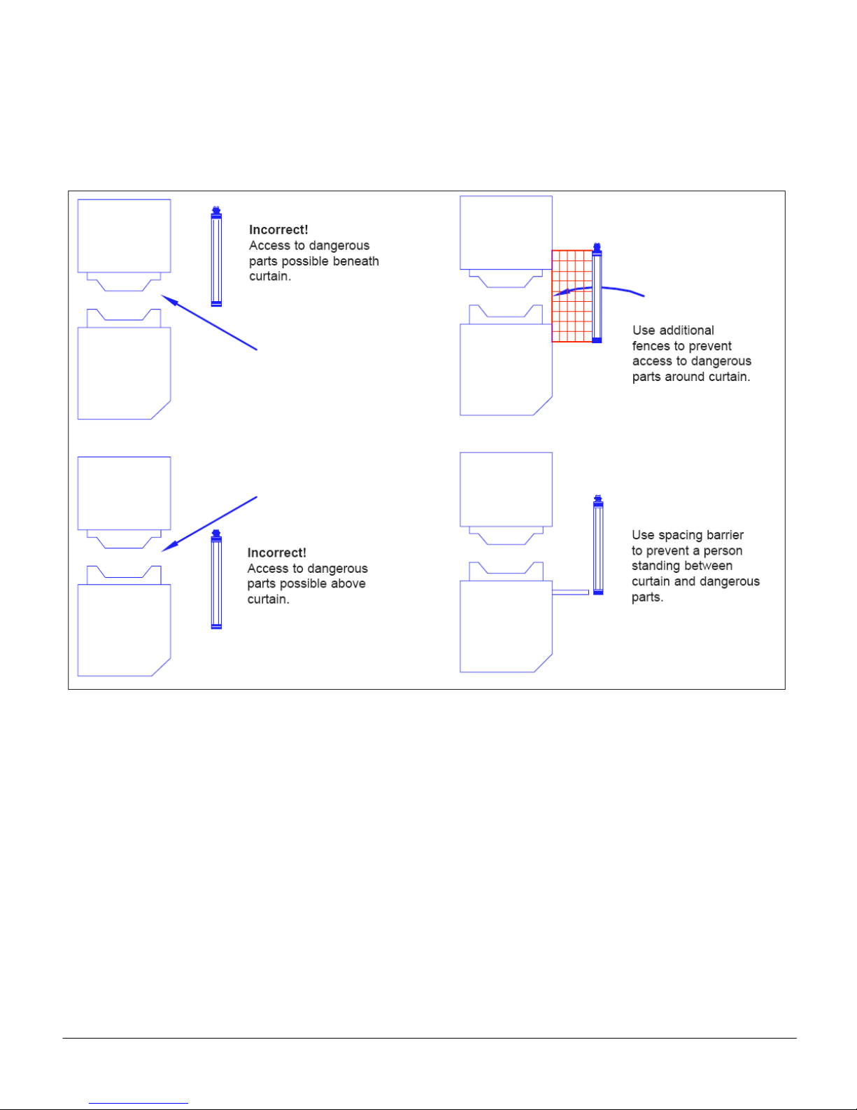
(e) Steps must be taken to prevent access to the
dangerous parts of t h e machine from an y direc tio n n ot
covered by the photo-electric curtain. Such steps could
include fixed or interlocking fences or screens,
additional photo-electr ic devices or pressure sens itive
mats. Similar steps should be taken to prevent a p erson
from st anding between the cur tain and the dangerous
parts of the machine.
(f) No devices other than those specified in this manual
should be connected to the internally-generated power
supply of the system.
(g) After installation, the machine/guard syste m must be
commissioned in ac cordanc e with the r equirem ents of
section 5.1.1 of this manual.
(h) Any covers removed during installation must be
replaced as soon as possible.
(i) At power on, af ter a power interruption or after the
curtain has been actuated, it must not be possib le for
the machine to star t (or restart) until a manual contr ol
has been operated. This is known as “start/restart
interlock”. The GS-120 can provide this function, but if it
is not installed, it must be provided elsewhere within the
safety system
(j) To avoid nuisance tripping, if a fluorescent lamp with
an electronic ballast is located within 5 feet (1.5 meters)
of the receiver unit, it mus t be outside of a 20º field of
view from the receiver unit (±10º about the center line).
If this is not practic al, a 60 H z fluorescent li ght fixture
should be used.
3.2 MECH ANICAL INSTALLATION
3.2.1 GENERAL CONSIDERATIONS
ANSI B11.19-1990 g ives guidance on the dim ensions
and positioning of photo-electric safety devices fitted to
industrial machines. The main considerations are
described below and are illustr ated in Figure 8.
(a) The appropriate protected height must be selected.
The curtain must be of sufficient height such that access
to the dangerous parts, from the direction of appr oach of
the operator, is only possible by obstructing the curtain
taking into account all possible operator positions.
(b) The c orrect minim um separation distanc e must be
observed. The curtain m ust be mounted in the correc t
position in relation to the dangerous parts of the
machine to take account of the stopping performance of
the machine, the curtain format used and the detection
capability of the curtain.
(c) Steps must be taken to prevent access to the
dangerous parts from any direction not covered by the
curtain and to prevent an operator from standing
between the curtain and the dangerous parts w ithout
obstructing the curtain. Additional mechanical guarding
will usually be necessary to achieve this.
TAPESWITCH CORPORATION Phone: 631-630-0442
100 Schmitt Boulevard
Farmingdale, New York 11735 www.tapeswitch.com
13 Fax: 631-630-0454
Release 7/2009 Ver. 1.0 Technical Manual: GS-120 Light Curtain Systems
The physical parameter s affecting the positioning are
the dimensions of the detection zone of the light curtain
(i.e. the protected height and the range) and the
minimum separation dis tan c e. T hes e ar e desc r ibed in
the following sections.
Figure 8
TAPESWITCH CORPORATION Phone: 631-630-0442
100 Schmitt Boulevard
Farmingdale, New York 11735 www.tapeswitch.com
14 Fax: 631-630-0454

Release 7/2009 Ver. 1.0 Technical Manual: GS-120 Light Curtain Systems
3.2.1.1 Multi-Sided Guarding
By using mirror columns the light curtain beams can be
deflected around corners t o form two and three sided
guard configurations. It should be borne in mind that for
each mirror used the range is reduced by approximately
20%. Also the alignment of systems with mirrors can be
difficult especially where the mounting surfaces are
uneven. It is therefore recommended that no more than
two mirrors are used between an y pair of emitter and
receiver units. Se e Figures 9, 10, an d 11 for diff erent
multi-sided guarding configurations.
Note: The arrangement shown in Figure 11 is not
recommended, as it is very difficult to determine that the
safety distance S is correct.
Figure 9 - Guarding a two-sided area
TAPESWITCH CORPORATION Phone: 631-630-0442
100 Schmitt Boulevard
Farmingdale, New York 11735 www.tapeswitch.com
Figure 10 – Guarding a 3-sided area
Figure 11 – Incorrect use of two-sided guarding
15 Fax: 631-630-0454

Release 7/2009 Ver. 1.0 Technical Manual: GS-120 Light Curtain Systems
Figure 12
3.2.2 CURTAIN DIMENSIONS
3.2.2.1 GS-120 Basic System
The curtain dimensions are defined by the protected
height and the range (i.e. the distance between the
emitter and receiver units ) . T he pr otec ted he igh t must
be selected to suit the application. The minimum range
for all systems is 500 millimeters. The maximum range
for systems with 30mm or 70mm detection capability is
15 meters (50 feet).
All the dimensions relating to the curtain, for each of the
GS-120 systems are s hown in Figure 12. T he upper
and lower boundaries of the curtain are indicated b y
arrows on the front window labels of each unit.
TAPESWITCH CORPORATION Phone: 631-630-0442
100 Schmitt Boulevard
Farmingdale, New York 11735 www.tapeswitch.com
16 Fax: 631-630-0454

Release 7/2009 Ver. 1.0 Technical Manual: GS-120 Light Curtain Systems
Figure 13
3.2.2.2 GS-120 Multi-Beam System
All the dimensions relating to the curtain, for
each of the Multi-beam systems (or multi-beam
slave systems) are shown in Figure 13.
TAPESWITCH CORPORATION Phone: 631-630-0442
100 Schmitt Boulevard
Farmingdale, New York 11735 www.tapeswitch.com
17 Fax: 631-630-0454

Release 7/2009 Ver. 1.0 Technical Manual: GS-120 Light Curtain Systems
3.2.2.3 GS-120 Cascaded Sy st e m
Additional flexibilit y to facilitate guarding in more than
one plane is provided, by the capability to connect slave
units to a basic or multi-beam master system.
The slave units can be ba sic or multi-beam systems,
with any of the defined detection characteristics of
30mm or 70mm.
The dimensions re lat ing t o the c urt ains , f or each slave
unit are as defined in the previous sections for each
model. The upper and lower boundaries of each curtain
are indicated b y ar rows on the front window labels of
each unit.
A maximum of two sets of slave units can be connected
to a master system as shown in Figure 14. Each
emitter-receiver pair has a type designation where:
Type GS-120/M is a master
Type GS-120/A is a slave
Type GS-120/D is a slave with a connector at each end
Master and slave units can be assembled up to a
maximum of 240 beams. Where:
30mm detection - 12 beams per 200mm curtain
70mm detection - 4 beams per 200mm curtain
Examples:
GS-120/M/1000/30 = 60 beams
GS-120/A/0400/70 = 8 beams
So, total = 68 beams
Notes:
1. When master/slave emitter-receiver sets have
different range capabilities, these must be
respected when systems are configured.
2. When master/slave emitter-receiver sets have
different detection capabilities, the separation
distance must be calculated and adhered to for
each set separately.
Figure 14
TAPESWITCH CORPORATION Phone: 631-630-0442
100 Schmitt Boulevard
Farmingdale, New York 11735 www.tapeswitch.com
18 Fax: 631-630-0454

Release 7/2009 Ver. 1.0 Technical Manual: GS-120 Light Curtain Systems
3.2.3 SEPARATION DISTANCE
Any machine, regardless of the efficiency of its braking
system, will take a certa in time to com e to rest after a
stop signal is generated.
The time from the instant that the c urtain is broken to
the instant that dangerous motion actually ceases is
called the “overall system response time”. The
dangerous parts will obviously continue to move during
this time. The curtain must therefore be positioned at a
certain minimum dis tance f rom the dang erous p arts to
prevent a person who h as obstruc ted the curtai n from
reaching the dangerous parts before they hav e stopped.
This distance is the “minimum separation distance” and
is defined as the distance, in the direction of approach,
between the physical point at which the curtain detects
an obstruction and the nearest dangerous parts.
ANSI B11.19-1990 provides guidelines on how to
determine the minimum separation distance for a given
application. Tapeswitch GS-120 systems are primarily
intended for use in norm al appr oach form at where t he
curtain is perpendicular to the direction of approach,
although they can be used in parallel and angled
approach formats.
3.2.3.1 Normal Approach
Normal approach form at is shown in Figure 15. For
normal approach format the inner edge of the front
window of each unit (i.e. the edge whic h is nearest to
the machine) should be considered to be t he point at
which an obstruction is detected. See plane X as
shown in Figure 15.
The effective sensing field of the device shall be located
at a distance from the nearest recognized hazard such
that the operator or others cannot reach the hazard with
a hand or other body part before stopping of the motion
during the hazardous portion of the machine cycle.
Figure 15
TAPESWITCH CORPORATION Phone: 631-630-0442
100 Schmitt Boulevard
Farmingdale, New York 11735 www.tapeswitch.com
19 Fax: 631-630-0454

Release 7/2009 Ver. 1.0 Technical Manual: GS-120 Light Curtain Systems
2.5
2.0
1.5
1.0
0.5
0.0
0.0 8.07.06.05.04.03.02.01.0
Blanked Dimensions or Minimum
Object Sensitivity in Inches
Penetration Fac tor D(pf) in Inc hes
DPF
1 inches
3.1 inches
8 inches
Detection
14mm
30mm
70mm
The minimum separation distance depends on the
application. The following formula should be used when
calculating this distance:
= K x (TS + TR+ TC+ TBM) + DPF
D
S
where:
DS = Minimum separation distance between the
device and the nearest point of operation
hazard in inches.
K = Hand speed constant.
See note.
T
= Stop time of the machine tool measured at
S
the final control element.
T
= Response time of the control system.
C
NOTE: TS and TC are usually measured by
a stop-time measurement device.
TAPESWITCH CORPORATION Phone: 631-630-0442
100 Schmitt Boulevard
Farmingdale, New York 11735 www.tapeswitch.com
= Response time of the presence-sensing device
T
R
and its interface, if any, as stated by the
manufacturer or as actually measured.
T
= Additional time allowed for the brake monitor (if
BM
used) to compensate for variations in normal
stopping time.
D
= Added distance due to t he penetration factor ,
PF
as recommended in the illustration below. The
minimum object sensitivity is stated by the
manufacturer. If beam blanking or floating
window features are used, these figures should
be added to the object sen s itivity figure before
using the chart.
NOTE: The value of the han d speed constan t, K, has
been determined by various studies.
Althou gh these studies indicate speeds of 63
in/sec to over 100 in/sec, they are not
conclusive determinations. The employer
should consider all factors, including the
physical ability of the operator, when
determining the value of K to be used.
20 Fax: 631-630-0454

Release 7/2009 Ver. 1.0 Technical Manual: GS-120 Light Curtain Systems
3.2.3.2 Parallel Approach
Parallel approach format is shown in Figure 16. For
parallel approach format the outer curtain detection limit
(as shown on the front window of each unit) m inus the
detection capability, should be considered to be the
point at which an obstruction is detected. See Plane X in
Figure 16.
Figure 16
For this type of protective equipment, the height H of the
detection zone shall not exceed 1000mm. If H is greater
than 300mm (200mm for non-industrial applicati ons),
the risk of undetected access beneath the detection
zone should be considered.
TAPESWITCH CORPORATION Phone: 631-630-0442
100 Schmitt Boulevard
Farmingdale, New York 11735 www.tapeswitch.com
21 Fax: 631-630-0454

Release 7/2009 Ver. 1.0 Technical Manual: GS-120 Light Curtain Systems
3.2.3.3 Angled Approach
If it is necessary to install the curtain, at an angle to the
direction of approach as shown in Figure 17, then the
following requirements apply:
An angle within ± 5° of normal or horizontal, need not be
considered to be angled, and the relevant formula used.
For detection zones which are positioned at angles
greater than ±5°, to the d irection of approach, account
shall be taken of the risks associated with the direction
of approach, and the most appropriate formula used.
3.2.3.4 Approach to ‘L’ Installation
If vertical and horizontal master/slave GS-120 light
curtains are used togeth er as in Figure 18, where the
vertical curtain is the main trip curtain and the horizontal
curtain performs presence sensing inside it, the
separation dista nce c alculations for the vert ical c urtain
are used. However, the detection capability calculations
of the horizontal curtain with respect to its height should
also be observed. Note: Where master/slave
combinations are used:
Total Master Unit Slave Unit
Response = Response + Response
Time Time Time
Figure 17
TAPESWITCH CORPORATION Phone: 631-630-0442
100 Schmitt Boulevard
Farmingdale, New York 11735 www.tapeswitch.com
Figure 18
22 Fax: 631-630-0454

Release 7/2009 Ver. 1.0 Technical Manual: GS-120 Light Curtain Systems
3.2.4 OPTICAL ALIGNMENT
The emitter and receiver units should be mounted facin g
each other at the same height with their axes al igned.
Misalignments, as il lustrated in Figure 19, should be
avoided. Tapeswitch offers a laser alignment t ool to add
visible assistance over longer range or when mirrors are
used. See section 4 for detailed information.
Figure 19
TAPESWITCH CORPORATION Phone: 631-630-0442
100 Schmitt Boulevard
Farmingdale, New York 11735 www.tapeswitch.com
3.2.5 REFLECTIVE SURFACES
There should be no reflective surfaces within the ‘fi eld of
view’ of the curtain units. Reflective surfaces within the
field of view can lead to non-detection of an obstruction.
The field of view of each of the emitter and receiver
units is approximately 5 degrees either side of the
optical axis.
A minimum distance from the optical axis to any
reflective surface must be observed. This distance
depends on the actual operating distance and must take
into account possible misalignment. This is illust rated in
Figure 20. The distance should be determined as
follows:
Operating distance L < 3m: X < 260 mm
Operating distance L > 3m: X > 0.0874L mm
Figure 20
23 Fax: 631-630-0454

Release 7/2009 Ver. 1.0 Technical Manual: GS-120 Light Curtain Systems
3.2.6 SYSTEMS IN CLOSE PROXIMITY
In order to avoid nuisance interference between
adjacent systems, whenever two or more emitterreceiver pairs are used within each other’s sensing
range, ensure that the fr ont window of an y unit is not
within the field of view of units of the opposite type
from other systems.
This can be achieved by ensuring that units of the same
type are mounted fac ing in opposite directions. See
Figure 21.
Figure 21
3.2.7 MOUNTING BRACKETS
Mounting brackets and their associated hard ware are
provided with the emitter and receiver units. The
brackets have been specially designed to allow
adjustment.
Each unit is supplied with two clamp brackets fitted, one
at each end. The clamp bracket is a short piece of
extruded aluminum which i s designed to interlock with
the unit housing extrusio n and to clamp in posit ion on
the rear of the hous ing by means of two set scr ews.
The set screws can be tightened or loosened with a
2mm Allen wrench, which is supplied with the unit. The
clamp bracket can be slid up and down the emitter and
receiver units to facilitate alternate positioning of the
bracket. The clamp brackets are a tight fit on the emit ter
and receiver units and may require some force to slide
them up and down on. The clamp bracket dimensions
are shown in Figure 22.
The clamp brackets can be moved to any position
over the length of the unit, but it is recommended
that they be kept in the supplied position.
Figure 22
TAPESWITCH CORPORATION Phone: 631-630-0442
100 Schmitt Boulevard
Farmingdale, New York 11735 www.tapeswitch.com
24 Fax: 631-630-0454

Release 7/2009 Ver. 1.0 Technical Manual: GS-120 Light Curtain Systems
Figure 24
This makes replacem ent of a unit much eas ier as
the new unit will have the brackets alre ady in the
correct position. The posi tion of the cl amps on the
units is shown in Figure 23.
The set screws may not be completely ti ghtene d in
the supplied position . These set screws must be
fully tightened before proceeding with the
installation. (A 2 mm Allen wrench is supplied for
use in tightening the brackets.) If these brackets are
not properly secured, the emitter and rece iver units
may shift causing nuisance tri pping, a false l ock-out
condition and/or a potential safety hazard.
Four wall brackets are supplied with each system
together with the 8 self-tapping screws needed to fix the
wall brackets to the clam p brackets. The wall brac ket
dimensions are shown in Figure 24.
The alternative mounting arrangements which these
brackets facilitate are shown in Figures 25, 26, & 27.
The internal construc tion of the units is such that the y
can withstand normal levels of vibratio n a nd shock. In
situations where the vibration of the machine cannot be
reduced to normal leve ls, v i br ation pr o of ing mountings
should be used.
Figure 23
TAPESWITCH CORPORATION Phone: 631-630-0442
100 Schmitt Boulevard
Farmingdale, New York 11735 www.tapeswitch.com
25 Fax: 631-630-0454

Release 7/2009 Ver. 1.0 Technical Manual: GS-120 Light Curtain Systems
2.56" (65mm)
1.85" (47mm)
2.56" (65mm)
Angular adjustment
screw
6mm dia.
mounting hole
Clamp plate
securing screw
.95" (24mm)
1.58" (40mm)
2.56" (65mm)
3.15" (80mm)
Figure 25
Figure 26
Figure 27
TYPE AB - MOUNTING BRACKETS
Type AB adjustable m ounti ng brac kets are an option al
choice for GS-120 Light Cu r tains . Combining a robust
design and quick release capability, these brackets
allow for s peed y installation and eas y interchange of a
light curtain unit without the need f or re-alignment. To
request this option when ordering your light curtain
please specify "AB" in your or der c ode. (part number
0978)
TAPESWITCH CORPORATION Phone: 631-630-0442
100 Schmitt Boulevard
Farmingdale, New York 11735 www.tapeswitch.com
26 Fax: 631-630-0454

Release 7/2009 Ver. 1.0 Technical Manual: GS-120 Light Curtain Systems
3.3 ELECTRICAL INTERFACE,
OPERATION, and INSTALLATION
This section is divided into two parts. The first part
discusses the interface and operation of the GS-120
system when the basic set (emitter and receiver) is
interfaced directly to the machine control circuitry by
means of the redundant solid state outputs.
The second section disc usses the interface when a ny
one of the various Tapeswitch control units is used.
The basic GS-120 system consists of an emitter and
receiver. The receiver unit provides two safety outputs.
These fail-safe outputs are solid-s tate PN P transistors
and are actively monitored and s hort-c irc uit protected.
The two outputs are independent of each other and
represent part of the redundancy of the overall light
curtain system. The outputs must always be in the
same state (i.e., both o utputs either on or off ). If one
output should fail i n the “on” position, the ot her output
will remain in the “off” position until the failure is
corrected. In order to maintain redundancy bo th outputs
must be interfaced to independent switching devices in
the machine control circuit (i.e., safety relays,
emergency stop relay packages, fail-safe PLC’S, etc.).
Both outputs must be used. The solid state ou tputs
can be interfaced directly to the machine control circuit
provided this circuitr y is compatible with the PNP-type
output. A number of manufacturers produce units
containing circuits of this type. Care should be taken to
ensure that the inputs of these units can accept t he PNP
outputs of the light curtain.
• The maximum current is 0.1 A.
• The output voltage, Ua , of each output is dependent
on the supply, Uv a nd the load and is given b y the
following expression Ua > Uv - 2v.
• If the solid state outputs are used directly, the
supply voltage to the light curtain (emitter and
receiver) must be c ommon to the supply voltage of
the device to which it will be interfaced.
• Both outputs must be used to maintain redundancy.
• Each output should be wired to independent switching
devices in the machine c ontrol circuit and SHOULD
NOT BE CONNECTED TOGETHER.
NOTE: The pair of solid state outputs are constantly
monitored and are designed to act as a single
of the
component in a fail-safe condition (i.e., if
outputs fails in the “on” position, the other output
will revert to the “off” position.
one
This output will remain “off” until the integri ty of th e
other output is restored. This level of integr ity mus t
be maintained throughout the machine control
circuit. It is the responsibility of the end user to
assure any fault within the safety circuit is detected
and that it puts the machine in a safe c o n d ition.
3.3.1 GENERAL
Both units must be suppl ied with 24 Vdc ± 20%. This
DC supply must be isolated by means of a safety
transformer which conforms to the requirements of
IEC61558-2-6. The emitter, receiver and interface unit
must use the same + 24V DC supply. The negative side
of the supply should be grounded and the cables should
be routed separately from power and motor drives.
The maximum cable length for each unit is 30 meters.
The power consumption is dependent on the protected
height of the system but is less than 12 VA.
The emitter and receiv er should be powered by a
common DC supply and connected to the system
ground. If power is removed from the emitter
only
the system may not automatically re-synchronize,
and may require power removal from the recei ver as
well in order to establ ish op tical communication and
synchronization. Power can be removed from the
receiver unit without any consequence to the
synchronization.
IMPORTANT
Power should be applied to both units at the
same time. If power is removed from the
emitter unit, power must also be removed
from the receiver unit.
3.3.2 EMITTER UNIT
3.3.2.1 General
The emitter unit has a five -pin male quick-disconnect
connector. Two pins for the DC supply, two fo r the test
input (see 3.3.2.2), and one for the grou nd. (protective
earth PE)
To connect to the emitter, a 5-pin female molded cable
assembly is necessary. This cable assembly is supplied
separately and is available in lengths of 15 feet (p/n
0972), 30 feet (p/n 0973), or 98 feet (p/n 0976). This
cable has an insulated j acket with color coded wires.
The cable has a fixed molded connector on one end and
flying leads at the other. The colors and corresponding
functions are shown in Figures 28 and 29.
TAPESWITCH CORPORATION Phone: 631-630-0442
100 Schmitt Boulevard
Farmingdale, New York 11735 www.tapeswitch.com
27 Fax: 631-630-0454

Release 7/2009 Ver. 1.0 Technical Manual: GS-120 Light Curtain Systems
Ground
Figure 28 – Emitter Connector
3.3.2.2 Test Input
On some machines, a test input is us ed to check the
interface between the phot o-electric saf ety device and
the machine. The input simulates the obstruction of the
curtain in order to c ycle the outp ut switchin g elem ents
and thereby expose an y fault before the next m achine
cycle. This input is appl ied during a safe part of the
machine cycle or at the end of the cycle.
If this function is used, a normally closed contact should
be connected as shown in Figure 29.
This contact must open for a minimum of 100ms. When
this contact is opened, th e light curtain safet y outputs
will be switched off and will remain off until the test
contact closes again and the curtain self-tests have
been successfully performed (assuming that the curtain
is not obstructed).
If the test input is not used, this input must be
jumpered.
NOTE: If the emitter cable is removed during
normal operation, the system will not return to
normal operation once the emitter is reconnected
until power is cycled on the receiver.
Figure 29 – Emitter Connections
3.3.3 RECEIVER UNIT
3.3.3.1 General
The GS-120 is availab le with two output m odes, PNP
and SSR, as shown in the order codes in section 1.3.
The PNP version has cross-monitored 24Vdc PNP
outputs, start/restart interlock and the ability to monitor
contacts from external devices (EDM). The SSR version
has volt-free contacts which are closed when the curtain
is clear, but does not have any start/restart interlock
function. This must be provided elsewhere in the safety
system. The receiver connector is shown in Figure 30.
The 24Vdc supply must have a 2A quick
blow in-line fuse fitted.
Figure 30 – Receiver Connector
TAPESWITCH CORPORATION Phone: 631-630-0442
100 Schmitt Boulevard
Farmingdale, New York 11735 www.tapeswitch.com
28 Fax: 631-630-0454

Release 7/2009 Ver. 1.0 Technical Manual: GS-120 Light Curtain Systems
Ground
3.3.3.2 PNP Version
3.3.3.2.1 Safety Outputs
This version has two 24 Vdc PNP outputs. The two
output signal switching devices (OSSDs) should be
wired to independent switching devices in the machine
control circuit. The OSSDs are solid-state de vices an d
are internally monitored and short-circuit protected. The
connections for the PNP version of the receiver are
shown in Figure 31.
The maximum current is 0.1A.
The output voltage, UA, of each OSSD is dependent on
the supply, UV, and the load which is given by the
following expression:
> UV - 2V
U
A
Figure 31- PNP Version Receiver Connections
3.3.3.2.2 Start/Restart and External Device
Monitoring (EDM)
In the PNP mode th e GS-120 can be set up for either
manual or autom atic start and restart. This functi on is
determined by the conn ections to the unit. In m anual
mode, the outputs will only switch on when the curtain is
clear and a reset s witc h is c losed and t hen opened . In
automatic mode the output s will be on whenever the
curtain is clear and off whenever the curtain is
obstructed.
The GS-120 also has the ability to monitor external
devices. This is achieved by using normally-closed
contacts of the external device and monitoring that they
are closed before allowing the outputs to switch from off
to on. The various wiring configurations for these
options are shown in Figures 32 to 35.
TAPESWITCH CORPORATION Phone: 631-630-0442
100 Schmitt Boulevard
Farmingdale, New York 11735 www.tapeswitch.com
Figure 32 – Auto Restart
Figure 33 - Auto Restart with EDM
Figure 34 – Manual Restart
29 Fax: 631-630-0454

Release 7/2009 Ver. 1.0 Technical Manual: GS-120 Light Curtain Systems
Ground
Figure 35 – Manual Restart with EDM
3.3.3.3 SSR Version
This version has two voltage-free solid-state outputs. It
operates in autom atic mode, so the outputs will be on
whenever the curtain is clear and off whenever the
curtain is obstructed. See Figure 36.
Figure 36 – SSR Version Wiring
TAPESWITCH CORPORATION Phone: 631-630-0442
100 Schmitt Boulevard
Farmingdale, New York 11735 www.tapeswitch.com
30 Fax: 631-630-0454

Release 7/2009 Ver. 1.0 Technical Manual: GS-120 Light Curtain Systems
3.3.4 INTERFACING TO A MACHINE
The interfacing of a l ight curtain to a machine can be
achieved by using discrete components or by means of
an interface unit such as the Tapeswitch SRUB.
All the relays shown are safety relays with positively
guided contacts. If this circuit is implemented using
discrete components, it is essential that this type of relay
is used.
3.3.4.1 PNP Version Manual Reset
It may be possible to connect the GS-120 directly to the
Machinery Primary Control Elements (MPCE) as shown
in Figure 37. The GS-120 provides the Start/Restart
function necessary to avoid unintended initiation of the
machine.
Figure 37 – PNP Version Manual Reset
Note: N/C contacts of K1 and K2 are used for
monitoring purposes. If EDM is carried out elsewher e,
the reset switch should be connected between pi n 2 and
pin 6 of the Receiver unit.
IMPORTANT
A number of manufacturers produce units containing
circuits of this type. Care should be taken to ensure that
the inputs of these units can accept the PNP outputs of
the light curtain.
TAPESWITCH CORPORATION Phone: 631-630-0442
100 Schmitt Boulevard
Farmingdale, New York 11735 www.tapeswitch.com
31 Fax: 631-630-0454

Release 7/2009 Ver. 1.0 Technical Manual: GS-120 Light Curtain Systems
3.3.4.2 PNP Version Auto Reset
The GS-120 can be used in Auto Restart mode as
shown in Figure 38. If this mode is selected, the Manual
Restart function must be provided elsewhere in the
machine safety control system (for example, in the
SRUB interface unit).
Note: The c onnection through 41 and 42 is used for
external monitoring (EDM). If an alternative safety relay
is used which does not have N/C contacts for
monitoring, then connect pin 2 to pin 6 on the Receiver
unit.
Figure 38 – PNP Version Auto Reset
IMPORTANT
A number of manufacturers produce units containing
circuits of this type. Care should be taken to ensure that
the inputs of these units can accept the PNP outputs of
the light curtain.
TAPESWITCH CORPORATION Phone: 631-630-0442
100 Schmitt Boulevard
Farmingdale, New York 11735 www.tapeswitch.com
32 Fax: 631-630-0454

Release 7/2009 Ver. 1.0 Technical Manual: GS-120 Light Curtain Systems
3.3.4.3 SSR Version
The interfacing of a GS-120 light curta in to a machine
can be achieved by means of an interface unit such as
the Pilz PNOZ 8. The circuit diagram for the PNOZ 8
and the typical c o nnec t ions to the GS-120 light curtain
and the machine are shown in Figure 39 below.
Figure 39 – SSR Version
IMPORTANT
A number of manufacturers produce units containing
circuits of thi s type. Care should be taken to ensure that
the inputs of these units can accept the volt-free outputs
of the light curtain, and that the outputs of the light
curtain are wired with one channel "pull up" and one
channel "pull down" so as to maintain the failure mode
integrity.
TAPESWITCH CORPORATION Phone: 631-630-0442
100 Schmitt Boulevard
Farmingdale, New York 11735 www.tapeswitch.com
33 Fax: 631-630-0454

Release 7/2009 Ver. 1.0 Technical Manual: GS-120 Light Curtain Systems
3.4 INITIAL CHECKING AND A LIGNMENT
The procedure for alignment is described below.
Apply power to the GS-120 system.
The amber indicator s on t h e emitter and recei ver u nits
should be lit. If either of the indicat ors is not lit, check
the wiring.
The yellow indicators on the em itter and the receiver
units should be in t he off state. If e ither of these two
indicators is flashing, there is a fault, contact your
Tapeswitch distributor. If the yellow indicator on the
emitter unit is on constantly, check the wiring as
described in sections 3.3.2 and 3.3.3.
The green indicator on the receiver unit should be lit, if
not, adjust the units into general alignment until the
green indicator comes on.
Adjust the units to optimum alignment as follows:
1. Slowly turn the emitter unit clockwise until the green
indicator on the receiver unit goes off and the red
indicator comes on. (Note this position.)
2. Then turn the em itter unit c ounter-cloc kwise, again
until the green ind icator goes of f and the red indicator
comes on. (Note this position.)
3. Set the emitter at the center of the two noted
positions.
4. Repeat steps 1, 2 and 3 but th is time turning the
receiver unit.
Using the test piece provided, obstruct the curtain. On
the receiver unit the green indicator should go off and
the red indicator comes on.
Move the test piece in an d out of the curtain several
times and check that the indicators change state
appropriately each time.
See section 5.2 of this m anual if the system does not
function as described above.
The installation of the machine can now be completed.
Before putting the machine into use, the complete
system (i.e. the machine and all its safeguarding
devices) should be commissioned by qualified personnel
and, as a minimum, the commissioning checks
described in section 5.1.1 of this manual should be
performed.
Periodic checks in accordance with section 5.1.2 should
be carried out at the prescribed intervals. Daily checks
to be performed on th e GS-120 system are detail ed in
section 5.1.3 of this m anual. In som e cases there are
specific statutory requirements concerning the
examination, inspectio n and test of a machine an d its
safety devices. It is for the user to determ ine if such
requirements exist f or the machine in question a nd to
ensure that those requirements are met.
TAPESWITCH CORPORATION Phone: 631-630-0442
100 Schmitt Boulevard
Farmingdale, New York 11735 www.tapeswitch.com
34 Fax: 631-630-0454

Release 7/2009 Ver. 1.0 Technical Manual: GS-120 Light Curtain Systems
4.0 INTERFACE AND AUXILIARY UNITS
4.1 GENERAL
In applications where the two PNP or solid state outputs
are not suitable for the machine control circuit, an
interface unit m ust be uti lized. T his interf ace unit m ay
be user supplied, provided it is compatible with either
the PNP or SSR outputs and has two channels. A
number of manufacturers produce units containing
circuits of this type. The interface unit must be de signed
to the same level of int egrit y as the GS-120 i n ord er to
maintain the same overall level of safety.
Several Tapeswitch interf a c e units are available whic h
offer options in configuring the input power source,
mounting package and type of electrical interface
desired. All of the units perform the actual switching of
the electrical circuit of the dangerous machine using
positively-guided saf ety relays. All of th e ac-powered
interface units (BSRSA and BSRUA-2) provide the
stepped-down +24 Vdc power for the GS-120 emitter
and receiver pair. The dc-powered interface units,
(SRUB an d SRUS), are powered b y an external +24
Vdc power supply and this supply must also power the
GS-120 emitter and receiv er pair. All of the interfac e
units provide isolation f rom the low am perage GS-120
solid state outputs (0.5 A each) and the potentially
higher amperage required by the machine control
circuitry. Each interface unit provides LED status
indicators. All LEDs will be discussed in the description
of the applicable interface units. These units are
described in the appendices of this document.
4.1.1 METHODS OF INTERFACING
All of the interface units have a m inim um of two saf ety
outputs. These outputs are to be interfaced with the
machine primary control elements (MPCEs). An
MPCE is defined as an e lectrically control led element
which directly controls the normal operating motion of a
machine such that it is the last (in time) to operate when
motion is initiated or arrested.
The safety output contacts of the interface unit must be
connected to a machine’s MPCEs in such a way that if
either of the safety output relays is switched off, then the
machine will be brought t o res t, r egardl es s of the state
of the other relay.
This gives assurance that the failure of a s ingle relay
cannot prevent the machin e from being stoppe d. The
safety output relays are cross-monitored within the
interface unit. This means any disparity between the
two relays will be detected. The machine will be
disabled until the cause of the disparity has been
removed. Such a disparity could be the loss of signal on
one of the two channels co ming from the light curt ain.
TAPESWITCH CORPORATION Phone: 631-630-0442
100 Schmitt Boulevard
Farmingdale, New York 11735 www.tapeswitch.com
The interface will only allow the safety relays to move to
the ON state if both channels are working correctly
together.
All interface units are provided with indicator lamps
which show the stat us of the interface. T he number,
color, meaning and location of the indicators may
change with the type of interface. All interfaces
however, have indicator s which specifically show the
commanded state of the output safety relays.
Both of these outputs must be used to take
advantage of the inherent redundancy of the
interface unit.
The two safety outputs are normally (NO). The outputs
are closed when no obstructions are in the light curtain
and no faults exist. Once the light curtain is broken the
outputs open. The state of the output may remain open
until a reset switch is applied (MANUAL RESET) or will
automatically close (AUTOMATIC RESET) once the
light curtain is cleared. Details of the resetting features
are discussed in the individual interface sections found
in the appendices.
The safety outputs can be used in several ways,
depending on the MPCEs found on the machine being
guarded. MPCE is the abbreviation for Machine
Primary Control Element. An MPCE is an electrically-
powered control device which directly controls the
guarded machines motion and is the final device in the
operating sequence when motion is either initi ated or
halted. This would be the main hydraulic control val ve
in a hydraulically controlled press. Some of the
common arrangements are described below:
• Normal risk m achine - These usual ly have a single
MPCE. In this case both normally open safety outputs
should be used together as shown in Figure 40.
• High risk machines - These should have 2 MPCEs. In
some countries, it is customary for both MPCEs to
operate in the sam e m ode. In th is c ase, eac h of the
normally open (NO) outputs controls a s i ngl e M PC E.
See Figure 41 for an illustration of the type of
interface. Any additional output contacts can be used
as a monitor, e.g. as an input to a PLC.
To protect the contacts of the safety output relays from
the effects of switching inductive loads, an appropria tely
rated power factor cor rection device must be inst alled
across t he MPCE coils. Fi gures 40 and 41 show Arc
Suppressors used for this pur pose. Arc Suppressors
are user supplied.
35 Fax: 631-630-0454

Release 7/2009 Ver. 1.0 Technical Manual: GS-120 Light Curtain Systems
Machine
Control
Voltage
Safety
Fuse
Safety
Output
1
Safety
Output
2
Arc
Suppressor
MPCE
1
Machine
Control
Voltage
Safety
Fuse
Safety
Output
1
MPCE
1
Arc
Suppressor
Safety
Fuse
Safety
Output
2
MPCE
2
Arc
Suppressor
CAUTION
Arc Suppressors must not be connected
across safety relay contacts.
Figure 40 - Interfacing a Machine with 1 MPCE
Figure 41 - Interfacing a Machine with Dual
SAFETY FUSES: It is good practice to protect the
safety r elays against welding due to a current s urge.
This can be done by current limiting designs in the
machine’s controls, or by simple fusing as shown in
Figure 40 and 41. The current through the safety
output contacts should be l imited to a level be low that
TAPESWITCH CORPORATION Phone: 631-630-0442
100 Schmitt Boulevard
Farmingdale, New York 11735 www.tapeswitch.com
Identical MPCEs
which could cause the c ontact to weld. Fuses with a
current rating less than that of the output contacts
should be used.
On the BSRSA Interface Unit, these safety (output
protection) fuses are par t of the unit. All of the other
interface units do not provide safety fuses (output
protection) and these fuses should be supplied
externally by the user.
4.1.2 SPECIAL INTERFACING CONSIDERATIONS
4.1.2.1 PNP Version Manual Reset
It may be possible to connect the GS-120 directly to the
Machinery Primary Control Elements (MPCE). The GS120 in this configuration provides the Start/Restart
function necessary to avoid unintended initiation of the
machine.
4.1.2.2 PNP Version Auto Reset
The GS-120 can be used in Auto Restar t m ode. If t his
mode is selected, the Manual Restart function must be
provided elsewhere in the machine safety control
system (for example, in the SRUB interface unit).
4.1.2.3 SSR Version
The interfacing of a GS-120 light curtain with SSR
outputs requires a controller that is compatible with
these devices. Care should be taken to ensure that the
inputs of this unit can accept the volt-free outputs of the
light curtain, and that the outputs of the light curtain are
wired with one channe l " pu l l up" and one channel "pull
down" so as to maintain the failure mode integrity.
36 Fax: 631-630-0454

Release 7/2009 Ver. 1.0 Technical Manual: GS-120 Light Curtain Systems
Figure 42
Connecting a GS-120 to an AS-i System
4.1.3 CONNECTIONS TO AN AS-i SYST E M
A GS-120 system c an be connected to an AS-i Safe
System using standard AS-i Safe I/O modules as shown
in Figure 42.
The connection of the Emitter and Receiver units to the
system is simply achieved by plugging into standard
AS-i components using the cables supplied.
Note: The power su pply leads of the GS-120 system
not
should
be connected di rectl y to the YELLOW AS-i
cable as this may cause AS-i data transmission
problems. It is recomm ended that this connection be
made using a decoupling network.
Alternatively the guard can be connected to the BLACK
AS-i cable (the auxiliary power cable).
TAPESWITCH CORPORATION Phone: 631-630-0442
100 Schmitt Boulevard
Farmingdale, New York 11735 www.tapeswitch.com
37 Fax: 631-630-0454

Release 7/2009 Ver. 1.0 Technical Manual: GS-120 Light Curtain Systems
5.0 PERIODIC CHECKING,
SERVICING, AND MAINTENANCE
5.1 PERIODIC CHECKING
5.1.1 COMMISSIONING CHECKS
The commissioning exam ination s hould be carried o ut
by persons who are competent and who possess all the
information supplied with the machine and its safety
equipment. The results of the examination sh ould be
recorded and copies of this record should be kept by the
user and the employer of the person performing the
examination. The person carrying out the examination
should ensure that the following general standard of
performance is met:
(a) It should not be possib l e f or the danger o us parts of
the machine to be set in motion while the light curtain is
penetrated.
(b) Penetration of the light curtain dur ing a dangerous
phase of the operation of the m achine shoul d result i n
the dangerous parts being arrested or, where
appropriate, assuming an otherwise safe condition,
before any part of a person can reac h th em . It shou ld
not be possible for the dangerous parts to be set in
motion until the curtain has been cleared, the safety
system has been restored to its normal condition, and
the machine controls have been reset.
The person performing the examination should also:
(c) Inspect the position of the light curtain to ensure that
it is set at the correct distance from the dangerous parts
of the machine as recorded on the machine information
label or plate.
(d) Ensure that additional safeguarding measures have
been provided where nec essary to prevent access to
the dangerous parts of the machine not protected by the
light curtain.
(e) Where appropriate, test the overall system response
time using a suita ble device and ensure that it is th e
same or less than that recorded on the machine
information label or plate.
(f) Test the detec tion capability of the light curtain as
described in section 5.1.4 of this manual.
(g) Examine the machine controls and c onnections to
the GS-120 system to ensure that the requirements
described in this manual a nd in the machine manual
have been met.
(h) Examine the stopping performance monitor (if
installed) to ensure that it is installed and functioning
correctly. Ensure that the means whereby the stopping
performance can be assessed by the operator is
indicating correctly.
(i) Test the muting arrangements (if installed).
(j) Examine brakes or clutches (if installed) as
recommended.
NOTE: No stopping performance monit or or mutin g
facility is provided with the basic GS-120 system
and there is no means provided for the connection
of such devices to the system. These devices may
however have been provided elsewhere in the
machine control system.
5.1.2 6 OR 12 MONTH PERIODIC CHECKS
These examinations should be carried out by competen t
persons. The results shou ld be recorded and a copy
kept by the user.
The person should ensure that the general standard of
performance as described in section 5.1.1 (a) and (b) is
achieved.
The person should perform the commissioning
inspections and tests detailed in sect ion 5.1.1. W hen
checking the stopping perform ance monitor, item (h),
any equally effective means of determining that the
overall system response time, as recorded on the
machine inform ation label or plate, is not exceed ed is
acceptable.
In addition the person should:
(a) Examine all switching elements in the switching
paths controlled by the ligh t curtain outputs to ensure
that they are functioning correctly and are not in need of
maintenance and or replacement.
(b) Inspect the machine to ensure that there are no
mechanical or structur al aspects which could prevent
the machine from stopping or assuming an otherwise
safe condition when called upon to do so.
(c) Examine and inspect t h e m achine controls and t he
connections to the GS-120 s ystem to ensure that no
modifications have b een made which cou ld adversely
affect that system, and that suitable modifications have
been correctly performed and properly recorded.
TAPESWITCH CORPORATION Phone: 631-630-0442
100 Schmitt Boulevard
Farmingdale, New York 11735 www.tapeswitch.com
38 Fax: 631-630-0454

Release 7/2009 Ver. 1.0 Technical Manual: GS-120 Light Curtain Systems
<150 mm
<150 mm
Test piece
5.1.3 DAILY/SETTING EXAMINATION
The following tests should be carried out daily by a
designated person appointed by the machine user. The
results should be r ecorded and a cop y shou ld be kept
on or near the machine. Specific statutory req uirements
may apply to certain types of machines. The desi gnated
person should:
(a) Check that access to the dangerous parts of the
machine is not possible from any direction not protected
by the light curtain and that side and rear guards are in
order.
(b) Check that the minimum distance from the
dangerous parts of the machinery to the light curtain is
not less than the distance stated on the machine
information label or plate.
(c) Check that it is not possible for a p erson to stand
between the dangerous parts of the machine an d the
light curtain.
(d) Check that when the muting facilit y (if installed) is
operative, the moving parts are no longer dangerous.
(e) Check that the stopping performance monitor (if
installed) is in use and is set up and functioning
correctly.
(f) Check that electrical enclosures are closed and
locked and that any keys have been removed for
retention by a designated person.
(g) Check for external signs of damage to equipment or
to electrical wiring.
(h) Check the detection capability of the GS-120 as
described in section 5.1.4.
5.1.4 CHECKING DETECTION CAPABILITY
5.1.4.1 GS-120 System
The detection capabi lity of the light curtain s hould be
checked as required in the previous sections using the
method described below. See Figure 43.
(a) With power app li ed to t he GS-120 system and wit h
the machine at rest, check that the light curtain is
functioning by observing the state of the appropriate
indicators. The green ind icator should be on and the
red indicator should be off.
(b) Insert the test piece provided with the 30 mm model
into the light curtain beam s. The axis of the test piece
should be perpendicular to the plane of the light curtain.
Starting at the top of the emitter unit, position the t est
piece less than 150 millimeters from the emitter surface ,
and pass it slowly down the front of the unit. While the
full diameter of the test piece is within the area defined
by the two arrow markers on the front window, the green
indicator should G O OFF AND RE MAIN OFF and th e
red indicator should BE LIT AND REMAIN LIT.
(c) R epeat the above tes t with the test pi ece inserted
close to the front of the rec eiver unit and with the tes t
piece inserted at the midpoint between the emitter and
receiver units. The indicators should behave as
described above whenever the test piece is betw een the
arrow markers.
At no time while the test piece is obstructing
the curtain should the green indicator come
on. If it does, the machine must be isolated
and must not be used until the cause has
been investigated.
(d) If the s ys tem passes the above tests proceed as
follows. Initiate a cycle of the machine a nd t hen ins ert
the test piece into the curtain. Upon insertion of the test
piece during dangerous motion, the dangerous parts
should come to rest without apparent delay.
If the machine does not stop or there is any
delay in its response, the machine must be
isolated and must not be used until the fault
has been rectified.
WARNING
WARNING
Figure 43 – Light Curtain Detection Test
TAPESWITCH CORPORATION Phone: 631-630-0442
100 Schmitt Boulevard
Farmingdale, New York 11735 www.tapeswitch.com
39 Fax: 631-630-0454

Release 7/2009 Ver. 1.0 Technical Manual: GS-120 Light Curtain Systems
5.1.4.2 GS-120 Multi-Beam System
The operation of the light curtain should be checked as
required in the previous sections using the method
described below and as shown in Figure 44.
(a) With power app li ed to t he G S-120 system and wit h
the machine at rest, check that the light curtain is
functioning by observing the state of the appropriate
indicators. The green indic ator should be on, and the
red indicator should be off.
(b) To test the curtain is operating correctly, insert your
hand in between the emitter and receiver units and
obstruct one of the beams. While the beam is
obstructed, the gree n indicator should GO OFF AND
REMAIN OFF and the red indicator should BE LIT AND
REMAIN LIT. Mo ve your hand in and out of the beam
several times and check that the indicators chang e state
each time as appropriate.
(c) Repeat the above test for eac h of the beams . The
indicators should behave as described above wheneve r
the beams are obstructed.
WARNING
At no time while a beam is obstructed should the
green indicator come on. If it does, the machine
must be isolated and must not be used until the
cause has been investigated.
(d) If the s ys tem passes the above tests proceed as
follows. Initiate a cycle of the m achine and then inser t
your hand into the curtain. Upon insertion of your hand
during dangerous m otion, the dangerous parts s hould
come to rest without apparent delay.
WARNING
If the machine does not st op or there is a ny delay in
its response the machine must be isolated and must
not be used until the fault has been rectified.
Figure 44
TAPESWITCH CORPORATION Phone: 631-630-0442
100 Schmitt Boulevard
Farmingdale, New York 11735 www.tapeswitch.com
40 Fax: 631-630-0454

Release 7/2009 Ver. 1.0 Technical Manual: GS-120 Light Curtain Systems
UNIT
STATE OF
INDICATORS
CAUSE(S) ACTIONS(S)
Emitter
Amber LED
not lit.
No power
to unit
Connect power
Red LED
lit steady
Test input
is open
Close test i nput
Red LED
flashing
Emitter unity
faulty
Replace emitter
unit
Receiver
Amber LED
not l it
No power
to unit
Connect power
Red LED
fully lit (no
obstruction
of cur t ain)
Units o ut
of alignment
Check ali gnment
Test input
open on
emitter
Check emitter
red LED
Emitt er unit
faulty
No power on
em itter unit
Check emitter
amber LED
Ye llo w LE D
flashing
Receiver
outputs are
shorted
Remove short
between outputs
Ye llo w LE D
Steady
Light Curtain
has been
programmed
Re conne ct hand
hel d blanking unit
and re-configure
to co r rect setti ng
5.2 SERVICING
The GS-120 system is designed to be ser viced at u nit
level. There are no user-serviceable parts within the
units.
When a safety-critical fault occurs in the GS-120 system
or in the machine interface, the machine will be
disabled. It is first neces sary to establish whether the
fault is in the GS-120 system or in the machine
interface.
Use Ta bles 1 and 2 in section 2.4 and Table 3 below to
identify faults within the GS-120 system.
NOTE: The emitter and receivers are not matched
pairs. They become mated pairs only upon
power up. It is not neces sary to replac e both
units, should one become faulty.
Table 3 – Fault Table
5.3 MAINTENANCE
There are no mechanical, electrical or optical
adjustments necessary. Apart from occasionally
cleaning of the windows on the emitter and receiver
units, GS-120 systems are mainten ance free. Use a
soft, lint-free cloth and an anti-static cleaner.
Do not use solvents of any kind.
TAPESWITCH CORPORATION Phone: 631-630-0442
100 Schmitt Boulevard
Farmingdale, New York 11735 www.tapeswitch.com
41 Fax: 631-630-0454

Release 7/2009 Ver. 1.0 Technical Manual: GS-120 Light Curtain Systems
EN 13849-1:2006 PLE, EN 954-1 CAT 4
6.0 TECHNICAL SPECIFICATIONS (Basic GS-120, Emitter and Receiver ONLY)
TAPESWITCH CORPORATION Phone: 631-630-0442
100 Schmitt Boulevard
Farmingdale, New York 11735 www.tapeswitch.com
42 Fax: 631-630-0454

Release 7/2009 Ver. 1.0 Technical Manual: GS-120 Light Curtain Systems
GUARDSTAR
BSRSA
POWER
CONSUMP TION:
RESET
B SERIES
System Controller
CORPORATI ON
R
240VAC
RESISTIVE LO AD
6.94
6.00
5.00
4.12
8.00
9.50
APPENDIX A – BSRSA INTERFACE UNIT
1.0 GENERAL DESCRIPTION
The BSRSA interface unit is designed as a standalone
control panel. It interfaces a GS-120 light curtain
(emitter and receiver) with the guarded machine’s
controls.
2.0 OPERATIONAL SEQUENCE AND LED
STATUS DESCRIPTION
When power is firs t applied to the light curtai n system
via the BSRSA:
• A red LED (H3) on the BSRSA controller should
illuminate indicating that the control unit has power.
• No pow er will be supplied to the em itter or receiver
of the light curtain and the output status indicators in the
BSRSA controller will not be illuminated. All of the
outputs will be de-energized and the output contacts will
be open, until a reset has been applied.
• Reset the system by the front panel key switch or the
external remote reset, if us ed. See below for details.
After the reset switch is rel eased, both the emitter and
receiver units of the light curtain should have amber
indicators illuminated which shows that power has been
applied. If the light curtain is properly aligned, the
receiver should have a green LED illuminated which
shows the light curtain is clear. If the receiver shows a
red LED illuminate d, then the lig ht curta in is either not
properly aligned, faulty, or obs tructed. Once the units
are properly aligned and any obstructions are removed,
the green LED shou ld be illum inated and the receiver
LEDs should f ollo w t he sta te of the light cur tai n (gr ee n
indicates curtain clear and red indicates curtain is
blocked, obstructed, or misaligned). With the green
LED illuminated on the receiver, the output status
indicator on the BSRSA controller should be green (H2).
The output status indicator on the BSRSA controller will
be red (H1) when the curtain is blocked, obstructed, or
misaligned.
The redundant safety outputs will follow the state of the
light curtain, i.e., if the light curtain is clear; safety
outputs 1 & 2 will be c losed ( energi ze d) , bu t if the light
curtain is obstructed, saf ety outputs 1 & 2 will b e open
(de-energized)). The safety outputs reset
the light curtain is cleared again. The safety outputs will
not reset (close/energize) if a fault exists.
The lockout contact will close (energize) once the reset
sequence has been completed. It will remain closed at
all times unless a fault has occurred or power has been
removed. The lockout contact does not follow the state
of the light curtain. Once t he lock out conditi on occur s
TAPESWITCH CORPORATION Phone: 631-630-0442
100 Schmitt Boulevard
Farmingdale, New York 11735 www.tapeswitch.com
automatically
(loss of power or failure) it will be necessary to reset the
system.
The monitoring output will follow the state of the safety
outputs and should be used for non-safety functions (i.e.
indication and status).
• External remote reset can be accomplished by
connecting a normally-open, momentary-contact switch
to terminal X2 between connections 1 and 2. (This will
operate in conjunction with or replace the front panel
key reset switch.)
3.0 MECHANICAL INFORMATION
Figure 45 shows the metal enclosure size and mounting
dimensions of the BSRSA interface unit. The
dimensions are in inches. The BSRSA enclosure is
rated for the operating environments found in most
manufacturing plants. Figure 46 shows an internal view
of the BSRSA interface unit.
4.00
Type no:
Serial no:
110-
TYPICAL
Sensing Uni t
by Tapeswitch
24V DC
50/60 HZ
30VA
Equals
8273
8.75
Supply Voltage:
Output Contac ts :
4.0A@ 240VAC
Safety System
Response Ti me
Response Ti me
+10MS
Tapeswith
100 SCHMITT BLVD FARMINGDALE. NY 11735 1-800-234-
Figure 45 – BSRSA Interface Unit Outline and
Dimensions
43 Fax: 631-630-0454

Release 7/2009 Ver. 1.0 Technical Manual: GS-120 Light Curtain Systems
Safety Outputs
to Machine Contro l s
W1
W2
Power
Input
EmitterReceiver
BSRSA
Controller
Figure 46 - BSRSA Interface Unit Internal Vi ew
4.0 ELECTRICAL CONNECTIONS
The BSRSA interface unit has four internal terminal
strips, designated X1, X2, X6, and X7. Each connection
point is m echanical ly suit able f or (1) 2.5mm
wire. Crimped ferrules or tinning must be used on all
stranded wires. Figure 47 shows the system block
diagram for the BSRSA controller.
Figure 47 - BSRSA System Block Diagram
Terminal X7 is for AC input power. Term inal X6 is f or
the +24 Vdc power input. All connections between the
BSRSA interface unit and the GS-120 light curtain
emitter and receiver units are made at terminal X2. All
connections between the BSRSA interface unit and the
machine’s control are m ade at t erminal X1. Figure 48
show details of the connections for the po wer, output,
and reset functions.
2
, 14 AWG
The interconnection diagr am (Figure 49) and the wire
run list (WRL) (Figure 50) show the proper terminal
numbers and associated functions for the cabling
between the GS-120 emitter and receiver units and the
BSRSA interface unit. Be sure to observe the color
coding shown to assure proper operation.
The cables for the interface between the GS-120 emitter
and receiver units and the BSRSA unit are not included
with the light curtain and m ust be ordered separ ate ly.
The emitter cable has five c onductors in an insulated
jacket. The receiver cable has eight conductors in an
insulated jacket. The cables have different connectors
and will only mate to the pr oper c omponent of the light
curtain.
The metal enclosure has four double knockouts capab le
of accepting standard ½” or ¾” conduit fittings. It is
recommended that any high vol tage connection to th e
BSRSA control unit be made with suitable cabling
and/or conduit protectio ns. The connections between
the BSRSA and the GS-120 em itter and rece iver units
are non-hazardous, low-vol tage signals and additio nal
protection of these cables is not necessary. It is
recommended that suitable fittings or cable grips be
used to maintain the moisture integrity of th e install ation.
It is strongly recommended that the low-voltage
connections be separated from the high-voltage
connections. Local electrical codes should be
observed.
5.0 FUSES
The BSRSA is equipped with four fuses, F1, F2, F 3, and
F4. See Figure 46 for the location of these fuses. Fuse
F1 is a 500 mA, 250 Vac slow-blow type, and is
intended to protect from potential shorts and surges on
the high voltage side of the interface unit. Fuse F2 is a
1.2 A, 250 Vac quick-blow type and is intended to
protect from potential shorts in the low voltage, 24 Vdc,
circuitry of the interface unit. Fuses F3 and F4 are
output protection fus es. These fuses are 3.15 A, 250
Vac slow-blow types, and protect the safety output relay
contacts from weld ing d ue t o c urr ent s urges or excess
loading. Care should be taken to replace any fuses with
the correct rating. While replacing any fuses, particular
attention should be given to the fus e holder. Excess
stress on the fuse holders during replacement can lead
to intermittent connections, which may cause nuisance
tripping and/or a nuisance l ock -out condition.
TAPESWITCH CORPORATION Phone: 631-630-0442
100 Schmitt Boulevard
Farmingdale, New York 11735 www.tapeswitch.com
44 Fax: 631-630-0454

Release 7/2009 Ver. 1.0 Technical Manual: GS-120 Light Curtain Systems
Specifications Data Tolerance
Supply Voltages
110 V AC
240 VAC
+ 10%
- 15%
24 VDC
+ 10%
- 15%
Safety
Outputs
Type
Positively guided, forced
contact
Contacts
Two (NO) for use with FSDS
(Final Switching Devices)
One (NO) for lockout use,
(Secondary Switching Device)
Rating
4.0 A resistive load @
240VAC
4.0 A resistive load @
24VDC
5 Hz maximum rate
Fusing Two (2), 3.15Amp, i nternal
Monitor/Auxiliary
Output
0.5 Amp, 48 VD C 10 Watt
max
Dimensions
9.50 in. (241mm) hi gh
7.00 in. (178mm) wide
4.12 in. (105mm) deep
Weight
Approxi mately 7 lbs.
Enclosure Rating
NEMA TYPE 1 (standard)
NEMA TYPE 12 (available)
Connecting
Terminals
Type
Captive terminals, with
removable headers
Capacity One 2.5m m sq. ( AWG 14)
6.0 TEST INPUT
The BSRSA interface includes a test input. This input is
used to check the interfac e between the ph oto-electric
safety system and the machine. It electrically simulates
an obstruction in the light curtain. While in the normal or
run mode, the test input is jumpered (closed). It is
opened and closed when used for testing. The
machine’s control logic can verify that the safety output
relays did, in fact, cycle, thereby exposing any fault
before the next machine cycle.
This test should be conducted during a safe part of the
machine cycle, or at the end of the cycle. While the test
input is opened, power i s removed from the light curtain
(both emitter and receiver). Once the test input is
closed, power is restored to the light curtain. The
emitter and receiver may take a few seconds to resynchronize, and, consequently, the safety outputs may
take a few seconds to r esum e t heir norm al state. T he
device connected to the test input should have a dr y
contact which is closed during the run mode and
momentarily opened during the test mode.
The test in put is located on term inal XI, connections 9
and 10. If the test input is not utilized, a jumper should
be installed across these connections. (This feature is
seldom used and, therefore, a removable jumper is
installed at the factory.)
7.0 MONITOR/AUXILLIARY OUTPUT
A non-safety monitor /auxiliary output is als o provided.
This is a solid sta te rela y output which is closed when
the light curtain is clear and is open when the light
curtain is obstructed, a fault exists, or a lockout
condition is present. This output is provided on terminal
X1, locations 1 and 2. This output can be used for
display and status indicat ion purposes. It m ust not be
used for safety-re lated machine contro l and switching
functions.
8.0 TECHNICAL SPECIFICATIONS
TAPESWITCH CORPORATION Phone: 631-630-0442
100 Schmitt Boulevard
Farmingdale, New York 11735 www.tapeswitch.com
45 Fax: 631-630-0454

Release 7/2009 Ver. 1.0 Technical Manual: GS-120 Light Curtain Systems
Safety Ou tput 1 (NO)
Monitor Output (NO)
Non-Safety
Lockout Output (N O)
Safety Ou tput 2 (NO)
Test Input
(jumper if not us ed )
101 2 3 4 5 6 7 8 9
X1
Terminal X1: 9 and 10 must be
jumpered if not used.
MACHINE CONTROL CONNECTIONS
2
1
Momentar y C o ntact N/ O
Exter n al R es et swi t ch - ( i f u sed )
X2
REMOTE RESET
X6
24 V DC In
X6/ 1: + 24 V DC
X6/2: 0 VDC
1 2
DC POW E R CO NNE CT I O NS
110 / 240
VAC
For 110 V :
Jump er 1 to 3
Jump er 2 to 4
For 240 V :
Jump er 2 to 3
N/C 1
6541 2 3
Line
Ground
Neutral
X7
AC POWER CONNECTIONS
Figure 48 - BSRSA Terminal Numbers and Functions
NOTE: Connection from the emitter and receiver
is made to terminal X2, see Figure 44 for details.
TAPESWITCH CORPORATION Phone: 631-630-0442
100 Schmitt Boulevard
Farmingdale, New York 11735 www.tapeswitch.com
46 Fax: 631-630-0454

Release 7/2009 Ver. 1.0 Technical Manual: GS-120 Light Curtain Systems
1 2 3
+
_
BN WH BU BK
GY
+24Vdc
GND
0V
DATA 1
DATA 2
PNP OUT 1
PNP OUT 2
1 2 3 4 5 6 4 5
0V
+24Vdc
GND
GND
7
8
TO
T I
GY
BUWH
BN
PKYLGN SHIELD
P1
J1
P2
J2
W2 W1
B Series
Receiver
B Series
Emitter
1 2 4 5 7 8
9
BSRSA Controller Light Curtain Schematic Diagram
3
6 10
X 2
Figure 49 –Light Curtain to BSRSA Interconnection Diagram
TAPESWITCH CORPORATION Phone: 631-630-0442
100 Schmitt Boulevard
Farmingdale, New York 11735 www.tapeswitch.com
47 Fax: 631-630-0454

Release 7/2009 Ver. 1.0 Technical Manual: GS-120 Light Curtain Systems
Cable # Cable Type
Color
Code
Function From To
RKT5-612/XX
Emitter
5 Pin Quick Disconnect
BSRSA
Termin a l X2
W1 " Brown +24VDC 1 10
W1 " White OV DC 2 9
W1 " Blue Test Out
3} Jumper 3 to 4, if not used
4} Jumper 4 to 3, if not used
No Connecti on
W1 " Black Test In No Connecti on
W1 " Gray Ground 5 4
RKT8-09/XX
Receiver
8 Pin Quick Disconnect
BSRSA
Termin a l X2
W2 " White OV DC 1 5
W2 " Brown 24VDC 2 6
W2 " Green Ground 3 3
W2 " Yellow Outp ut 1 4 7
W2 " Gray Output 2 5 8
W2 " Pink Da ta (-) 6} Isolate 6 & 7 No Connecti on
W2 " Blue Data (+) 7} Isolate 6 & 7 No Connection
W2 " Shield Ground 8 Ground
Figure 50 – Wire Run List for BSRSA
TAPESWITCH CORPORATION Phone: 631-630-0442
100 Schmitt Boulevard
Farmingdale, New York 11735 www.tapeswitch.com
48 Fax: 631-630-0454

Release 7/2009 Ver. 1.0 Technical Manual: GS-120 Light Curtain Systems
APPENDIX B – BSRUA-2 INTERFACE UNIT
1.0 GENERAL DESCRIPTION
The BSRUA-2 interface unit is designed to be
incorporated into the user’s machine control system. It
interfaces either one or two GS-120 light curtains with
the protected machine’s controls.
2.0 OPERATIONAL SEQUENCE AND LED
STATUS DESCRIPTION
2.1 CONFIGURED FOR ONE
LIGHT CURTAIN
When power is first applied to the light curtain system:
• Two amber LEDs on the BSRUA-2 Controller should
illuminate, indicating that the control unit has power
(system status LEDs for channel 1 & channel 2).
• Power is automatically applied to the emitter and
receiver units and, if the s ystem is properl y connected
and aligned (see the follo wing w iring i nform ation), a nd
the l ight curtain is clear with no fau lts, the BSRUA-2
controller should have two green LEDs illuminated.
These LEDs indicate that the output status (for channel
1 and channel 2) is “on” and the redundant output safety
relays are in the “on” state or closed. T he outputs wil l
remain closed until an obstruction or fault occurs in the
light curtain. When the light curtain is obstructed, both
red LEDs will illuminate and flash. These LEDs indicate
that the output status (channel 1 and channel 2) is “off”
and the redundant output s afety relays are in the “of f”
state or opened.
The outputs will remain opened until the light curt ain is
clear. The outputs follow t he state of the light curtain
and reset AUTOMATICALLY without any operator
intervention. It is important to note the BSRUA-2
controller does not distin guish between a light curtain
fault, obstruction, m isalignm ent, or wiring error. All of
these conditions caus e the BSRU A-2 to respond as if
the light curtain is obstructed and the redundant safety
outputs will be in the “off” state (opened).
LIGHT CURTAINS
2.2. CONFIGURED FOR
When power is first applied to the light curtain system:
• Two amber LEDs on the BSRUA-2 Controller should
illuminate indicating that the control unit has power
(system status LEDs for channel 1 and channel 2).
• Power is automatically applied to the emitters and
receivers on both light curt ains, and, if the system is
properly connected and aligned (see the following wiring
TWO
information), and the light curtains are clear with no
faults, the BSRSUA-2 Controller should have two green
LEDs illuminated. These LEDs indicate the output
status (for channel 1 and channel 2) is “on” and the
redundant output safet y relays are in the “on” state or
closed. The outputs will remain closed until an
obstruction or fault occurs in either of the two light
curtains. When a light curtain is obstructed, the
corresponding red LED will illuminate and flash. These
LEDs indicate the output status (both redundant safety
outputs are “off”), and also identif y which light curtain
(emitter 1/receiver 1 or em itter 2/receiver 2) h as been
obstructed. Channel 1 flashing red indicates t hat light
curtain one has been obstructed, and channel 2 flashing
red indicates that light curtain two has been obstructed.
For the light curtain wh ich is unobstructed, the green
output status LED will remain steadily lit.
It is important to note that although a green LED status
indicator may be illuminated, the redundant safety
outputs may actually be off as a result of the other light
curtain being obstructed. The LEDs are designed to
assist the user determine which light curtain has caused
the output to go to the off state.
The outputs will remain opened until both light curtains
are clear. The outputs follow the states of the light
curtains and reset AUTOMATICALLY without any
operator intervention. It is important to note the
BSRUA-2 does not distinguish bet ween a light curtain
fault, obstruction, m isalignment, or wiring error. All of
these conditions cause the BSRUA-2 to respond as if a
light curtain is obstructed, and the redundant safety
outputs will be in the “off” state (opened).
3.0 MECHANICAL INFORMATION
Figure 51 shows the case size and mounting
dimensions of the BSRUA-2 interface unit. All
dimensions are in millimeters. The unit must be
mounted in an enclosure rated for the known operating
environment. In most cases, the unit will fit into an
existing machine’s contr ol unit panel. The unit snaps
onto a common electrical mounting rail, style DIN EN 50
022-35.
TAPESWITCH CORPORATION Phone: 631-630-0442
100 Schmitt Boulevard
Farmingdale, New York 11735 www.tapeswitch.com
49 Fax: 631-630-0454

Release 7/2009 Ver. 1.0 Technical Manual: GS-120 Light Curtain Systems
73
118
16151413121110987654321
17181920212223242526272829303132
152
MOUNT ON TOP HAT DIN RA IL
- DIN EN 50 022-35
Safety Out p u ts
to Machine Contro ls
W1
W2
Power
Input
Emi tt er
Receiver
BSRUA-2
Controller
W1
W2
W1A
Power
Input
Emitter #1
Emitter #2
W2A
Receiver #1
Safety Outputs
to Machine Controls
Receiver #2
BSRUA-2
Controller
Figure 51 - BSRUA-2 Interface Unit
Outline & Dimensions
4.0 ELECTRICAL CONNECTIONS
Figure 51 also shows the 32 integral connection
terminals, in two rows along the top of the interface unit.
The terminals are num bered 1 to 32. Eac h ter m inal is
suitable for up to two (2) 2.5mm
Crimped ferrules or tinning must be used on all s tranded
wires.
Figures 52 and 53 show system block diagrams for the
BSRUA-2 Controller. Figure 52 shows the configuration
for one light curtain. Figure 53 shows the configuration
for two light curtains. Figure 54 shows the terminal
numbers for the input and output functions (Input P ower,
ac/dc, and the redundant safety outputs). These
functions and terminal numbers are the same for either
the one or two light curtain configuration. The necessary
jumpers for the different configurations are noted. They
must be installed properly in order to insure the correct
and safe operation of the s yst em. Some jumpers may
be factory installed, an d the user m ust insure that the
unit is configured properly for the intended use.
All connections between the BSRUA-2 and the light
curtain(s) must be made with the proper emitter and
receiver cables (ordered separately).
For the case where one light cur tain is used, refer to
Figures 55 and 56. These s how the interconnection
diagram and the wire run list (WRL) and give the proper
terminal numbers and their associated functions for the
cabling between the GS-120 Series emitter and receiver
units and the BSRU-2A controller.
For the case where two light curtains are used, refer to
Figures 57 and 58. These s how the interconnectio n
diagram and the wire run list (WRL) and give the proper
terminal numbers and their associated functions for the
TAPESWITCH CORPORATION Phone: 631-630-0442
100 Schmitt Boulevard
Farmingdale, New York 11735 www.tapeswitch.com
2
(14 AWG) solid wires.
cabling between the GS-120 Series emitter and receiver
units and the BSRU-2A controller.
Be sure to observe the color coding sho wn to assure
proper operation.
Figure 52 – System Block Diagram
for the BSRUA-2 Interface Unit
Configured for ONE Light Curtain
(See Figures 55 and 56 for detailed connections)
Figure 53 - System Block Diagram
for the BSRUA-2 Interface Unit
Configured for TWO Light Curtains
(See Figures 57 and 58 for detailed connections)
50 Fax: 631-630-0454

Release 7/2009 Ver. 1.0 Technical Manual: GS-120 Light Curtain Systems
Specifications Data Tolerance
Supply Voltages
110 V AC
240 VAC
+ 10%
- 15%
24 VDC
+ 10%
- 15%
Safety
Outputs
Type
Positively guided, forced
contact
Contacts Two normally open (NO)
Rating
4.0 A resistive load @ 240VAC
4.0 A resistive load @ 24VDC
5 Hz maximum rate
Fusing 3.0 A recommended, by user
Dimensions
6.00 in. (152mm) long,
2.88 in. (73mm) wide,
4.65 in. (118mm) high
Weight
Approxi mately 2 lbs.
Enclosure Rating
IP 20
Enclosure Mounting
DIN EN 50 022-35
Connecting
Terminals
Type Captive terminals
Capacity Two 2.5mm sq. (AWG 14)
5.0 FUSES
The BSRUA-2 is equip ped with two fus es, F1 and F2.
Both fuses are located on the top of the Din Rail
enclosure. These fuses are secured with a springloaded twist mechanism. They are easily accessed with
a common flathead scre w driv er. Fuse F 1 is a 1 amp,
250 Vac, quick-blow type, and is intended to protect
from potential shorts and surges on the high-voltage
side of the interface unit. Fuse F2 is a 2 amp, 250 Vac
quick-blow type, and is int e nded to protect from shorts
and surges in the low-voltage, 24 Vdc circuitr y of the
interface unit. It is recommended that external fuses be
used to prevent the safety output contacts from welding
(as described in section 4.1.1 of the main document).
6.0 TEST INPUT
The BSRUA-2 i nterface provides a test input f or each
light curtain . This input is used to c heck the interfac e
between the photo-electric safety system and the
machine. It elec trical ly sim ulates an o bstr uction in the
corresponding lig ht c urtai n. While in the normal or run
mode, the test input is jumpered (closed). It is opened
and closed when used for testing. The machine’s
control logic can verify that the safety output relays did,
in fact, cycle, thereby exposing any fault before the next
machine cycle.
This test should be conducted during a safe part of the
machine cycle, or at the end of the cycle. W hile this
input is open, power is removed from the corresponding
light curtain (bot h em itter and rec eiver). O nce the test
input is closed, power is restored. The emitter and
receiver may take a few seconds to re-synchronize, and,
consequently, the safety outputs may take a few
seconds to resume their normal state. The device
connected to the tes t input should have a dry contac t
which is closed during the run mode and mom entarily
opened during the test mode.
The test inputs are located at terminals 7 and 8 for light
curtain num ber one and terminals 19 and 20 f or light
curtain number two. The test input on terminals 19 and
20 is active for the TWO light curtain configuration
ONLY. This input will ha ve no ef fec t in the single light
curtain configuration. If these inputs are not used,
jumpers should be insta lled on these term inals. (This
feature is seldom used and, therefore, removable
jumpers are installed at the factory).
TAPESWITCH CORPORATION Phone: 631-630-0442
100 Schmitt Boulevard
Farmingdale, New York 11735 www.tapeswitch.com
7.0 TECHNICAL SPECIFICATIONS
51 Fax: 631-630-0454

Release 7/2009 Ver. 1.0 Technical Manual: GS-120 Light Curtain Systems
26
27
28
Live
Ground
Neutral
AC Power Input
2
3
+24V DC
OV DC
DC Input Power
FOR AC POWER
Redundant
Safety Outputs
N/O
Output 1
N/O
Output 2
23
21
Test Inputs (if used)
7
8
19
20
110VAC: Jumper 29 to 31 and 30 to 32
240VAC: Jumper 30 to 31
24
22
JUMPERS
Jumper 1 to 2, 4 to 9 Jumper 1 to 2, 7 to 8 (if not used)
5 to 14, and 7 to 8 (if not used) 19 to 20 (if not used)
For ONE Light Curtain
Figure 54 - Input and Output Functions, Jumper Details and
Terminal Numbers for the BSRUA-2
For TWO Light Curtains
TAPESWITCH CORPORATION Phone: 631-630-0442
100 Schmitt Boulevard
Farmingdale, New York 11735 www.tapeswitch.com
52 Fax: 631-630-0454

Release 7/2009 Ver. 1.0 Technical Manual: GS-120 Light Curtain Systems
1 2 3
+
_
BN WH BU BK
GY
+24Vdc
GND
0V
DATA 1
DATA 2
PNP OUT 1
PNP OUT 2
1 2 3 4 5 6 4 5
0V
+24Vdc
GND
GND
7
8
TO
T I
GY
BUWH
BN
PKYLGN SHIELD
P1
J1
P2
J2
W2 W1
B Series
Receiver #1
B Series
Emitter #1
1 2 4 5 7 8 9 14 15 16 25 27
BSRUA-2 Controller
BSRUA-2 Controller Wiring Diagram for ONE Se nsing Unit Configuration
Figure 55 – Interconnection Diagram for the BSRUA-2 ONE Light Curtain Configuration
TAPESWITCH CORPORATION Phone: 631-630-0442
100 Schmitt Boulevard
Farmingdale, New York 11735 www.tapeswitch.com
53 Fax: 631-630-0454

Release 7/2009 Ver. 1.0 Technical Manual: GS-120 Light Curtain Systems
CABLE # CABLE TYPE
COLOR
CODE
FUNCTION FROM TO
RKT5-612/XX
Emitter
5 Pin Quick D isconnect
BSRUA-2
W1 " Brown +24V D.C. 1 15*
W1 " White OV D .C. 2 16*
W1 " Blue Test Out
3} Jumper 3 to 4, if not used
4} Jumper 4 to 3, if not used
No Connection
W1 " Black Test In No Connection
W1 " Gray Ground 5 25, 27, or Ground
RKT8-09/XX
Receiver
8 Pin Quick D isconnect
BSRUA-2
W2 " White OV D .C. 1 16*
W2 " Brown 24V D.C. 2 15*
W2 " Green Ground 3 25, 27, or Ground
W2 " Yellow Outp ut 1 4 4
W2 " Gray Output 2 5 5
W2 " Pink D ata (-) 6} Isolate 6 & 7 No Connection
W2 " Blue Data (+) 7} Isolate 6 & 7 No Connection
W2 " Shield Ground 8 Ground
* Denotes Double Connection
Figure 56 – Wire Run List for the BSRUA-2 ONE Light Curtain Configuration
TAPESWITCH CORPORATION Phone: 631-630-0442
100 Schmitt Boulevard
Farmingdale, New York 11735 www.tapeswitch.com
54 Fax: 631-630-0454

Release 7/2009 Ver. 1.0 Technical Manual: GS-120 Light Curtain Systems
Figure 57 – Interconnection Diagram for the BSRUA-2 TWO Light Curtain Configuration
TAPESWITCH CORPORATION Phone: 631-630-0442
100 Schmitt Boulevard
Farmingdale, New York 11735 www.tapeswitch.com
55 Fax: 631-630-0454

Release 7/2009 Ver. 1.0 Technical Manual: GS-120 Light Curtain Systems
CABLE # CAB LE TYPE
COLOR
CODE
FUNCTION FROM TO
RKT5-612/XX
Emitte r #1
5 Pin Quick D isconnect
BSRUA-2
W1 " Brown +24V D.C. 1 17*
W1 " White OV D.C. 2 18*
W1 " Blue Te st Out
TWIS T PAIR TOG ETHER
Black and Blue Wire
No Connection
W1 " Black Te st In No Connection
W1 " Gray Ground 5 25, 27, or Ground
RKT5-612/XX
Emitte r #2
5 Pin Quick D isconnect
BSRUA-2
W1A " Brown +24V D.C. 1 15*
W1A " White OV D .C. 2 16*
W1A " Blue Test Out
TWIS T PAIR TOG ETHER
Black and Blue Wire
No Connection
W1A " Black Te st In No Connection
W1A " Gray Ground 5 25, 27, or Ground
RKT8-09/XX
Receiver #1
8 Pin Quick D isconnect
BSRUA-2
W2 " White OV D .C. 1 18*
W2 " Brown 24V D.C. 2 17*
W2 " Green Ground 3 25, 27, or Ground
W2 " Yellow Output 1 4 4
W2 " Gray Output 2 5 5
W2 " Pink Data (-) 6} Isolate 6 & 7 No Connection
W2 " Blue Data (+) 7} Isolate 6 & 7 No Connecti on
W2 " Shield Ground 8 25, 27, or Ground
RKT8-09/XX
Receiver #2
8 Pin Quick D isconnect
BSRUA-2
W2A " White OV D .C. 1 16*
W2A " Brown 24V D.C. 2 15*
W2A " Green Ground 3 25, 27, or Ground
W2A " Yellow Outp ut 1 4 9
W2A " Gray Output 2 5 14
W2A " Pink Data (-) 6} Isolate 6 & 7 No Connection
W2A " Blue Data (+) 7} Isolate 6 & 7 No Connection
W2A " Shield Ground 8 25, 27, or Ground
* Denotes Double Connection
Figure 58 – Wire Run List for the BSRUA-2 TWO Light Curtain Configuration
TAPESWITCH CORPORATION Phone: 631-630-0442
100 Schmitt Boulevard
Farmingdale, New York 11735 www.tapeswitch.com
56 Fax: 631-630-0454

Release 7/2009 Ver. 1.0 Technical Manual: GS-120 Light Curtain Systems
APPENDIX C – SRUB INTERFACE UNIT
1.0 GENERAL DESCRIPTION
The SRUB interface unit is designed to be incorporated
into the user’s machine control system. It interfaces a
GS-120 light curtain with the protected machine’s
controls. The SRUB requir es a +24 Vdc input, which
must be common with the +24 Vdc. supplied to the light
curtain.
2.0 OPERATIONAL SEQUENCE AND LED
STATUS DESCRIPTION
Note: The LEDs on the SRUB provide status indication
of the o utput state of the saf ety relays onl y. No status
indicators for the light curtain (emitter and receiver) are
provided on this unit.
2.1 RESETTING OPTIONS
The SRUB interface can be configured for either a
manual (latched) reset or and automatic res et. In the
manual reset mode, the safety outputs will go to the “off”
state (opened) once the light c urtain is obstruc ted and
remain in the “off” state until the obstruction is removed
and an external (user supplied) reset switch is activate d.
Once this reset sequence is completed, the safety
outputs will resume the “on” state (closed). In the
automatic reset mode, the safety outputs will follow the
state of the light curtain (i.e., light curtain clear: outputs
“on” (closed), light curtain obstructed: outputs “off”
(opened). The operational sequence for both reset
options is described below.
2.1.1 Manual Reset
When power is first ap plied to a light curtain s ystem in
manual reset mode:
• No LEDs will be illuminated until a manual (external)
reset is applied.
• Once the external reset is applied, the two green
LEDs (channel 1 and channel 2) will illuminate.
(Provided the system is properly wired, no faults exist
and the GS-120 emitter an d r eceiv er units have pow er
and are properly aligned.) This indicates that both
safety relay outputs are in the “on” or closed state. Both
LEDs must be illuminated in order for the guarded
machine to operate.
• These outputs will remain “on” (closed) until the light
curtain is obstructed, faulty or misaligned. If an
obstruction occurs, both green LEDs will go off and
remain off. The LEDs will remain off, even if the light
curtain is cleared, until a reset is applied.
• Once a reset is ap pl ied the two LEDs will illumina te,
and the safety output relays will return to the “on”
(closed) state.
2.1.2 Automatic Reset
When power is first ap plied to a light c urta in s ystem in
automatic reset mode:
• Both green LEDs will illuminate and the safety output
relays will be “on” (clos ed). T he LEDs and outputs will
remain on, provided the light curtain is clear.
• When the light curtain is obstructed, both LEDs w ill go
off and the safety outputs contac ts will also go to the
“off” (open) state. The y will remain off until the light
curtain is clear.
• Once the obstruction is removed, both LEDs will
illuminate and both safety output relays will return to the
“on” state.
• If one of the output signals from the GS-120 light
curtain is disconnected, the corresponding LED
(channel 1 or channel 2) will go off . Both saf et y output
relays will also go off and remain off. The system will n ot
reset, even if the signal is res tored. This condition is
considered a catastrophic failure and requires a powerdown/power-up cycle to restore normal operation
(provided this failure has been rectified).
3.0 MECHANICAL INFORMATION
Figure 59 shows the case size and mounting
dimensions of the SR UB in terf ace unit. A ll dim ensions
are in millimeters. The unit must be mounted in an
enclosure rated for the k nown operating environment .
In most cases, the unit will fit into an existing machine’s
control unit panel. The unit snaps into a common
electrical mounting rail, style DIN EN 50 022-35.
TAPESWITCH CORPORATION Phone: 631-630-0442
100 Schmitt Boulevard
Farmingdale, New York 11735 www.tapeswitch.com
57 Fax: 631-630-0454

Release 7/2009 Ver. 1.0 Technical Manual: GS-120 Light Curtain Systems
118.7mm
113.6mm
70.0mm
Mount on Top Hat
DIN Rail
DIN EN 50 022-35
100.0mm
72.0mm
EmitterReceiver
+24V D.C.
Supply
SRUB
Controller
Safety Outputs
to Machine
Controls
W1
W2
W3
Figure 59 - SRUB Interface Unit
Outline & Dimensions
4.0 ELECTRICAL CONNECTIONS
The SRUB controller has twenty integral connection
terminals, in two rows, a long the top of the unit. The
terminals are marked according to their intended
function. Each terminal is suitable for up to two (2)
2.5mm² (14 AWG) solid wires. Crimped ferrules or
tinning must be used on a ll st randed w ires . Figure 60
shows the system block diagram for the SRUB
controller. Figure 61 shows the term inal numbers for
the various input and output functions.
Particular attention should be given to the jumper
placements for configuring MANUAL RESET and
AUTOMATIC RESET. These jumpers must be inst alled
properly in order to insure the correct and safe ope ration
of the system.
Note: Improper installation of the jumpers may lead to
false indication of the two green LEDs (channel 1 an d
channel 2). For example, both LEDs may be
illuminated, indicating both safety outputs are “on”
(closed), however, the outputs may actually be “off”
(opened) without the proper jumper configuration.
Figures 62 and 63 sho w the interconnec tion diagram
and the wire run list (WRL) and give the proper terminal
numbers and their associat ed func tions f or the cablin g
between the GS-120 Series emitter and receiv er units
and the SRUB controller. All connections between the
SRUB and the light curtain (emitter and receiver ) must
be m ade with the proper emitter and receiver cables
(order separately).
Figure 60 System Block Diagram
For the SRUB Interface Unit
TAPESWITCH CORPORATION Phone: 631-630-0442
100 Schmitt Boulevard
Farmingdale, New York 11735 www.tapeswitch.com
58 Fax: 631-630-0454

Release 7/2009 Ver. 1.0 Technical Manual: GS-120 Light Curtain Systems
Operating voltage
24 VDC at +/- 10%
Power consumption
approxi mately 5 VA
Contact configuration 2 N/O sa fety contact ,
1 N/C auxiliary contact
Co n ta ct typ e
Relay positive gui ded
Operating temperature
-25ºC to +50ºC
Termin a l/Ho using style D IN 40050 (Terminal IP20)
(Housing IP 40)
Conductor connection 2 x 2.5mm
2
solid wire DIN 26206
or 1 x 1.5mm
2
stranded wire with
ferrule D IN 46228
Max switching capacity
1500 VA
Switching voltage
250 VAC, 24 VDC Resistive load
Switching current
6A AC, 6A DC
4.1 MONITOR INPUT
(Manual Reset Mode ONLY)
The SRUB interface unit provides a mac hine monitor
input. This monitor input receives a closed contact from
the machine’s control c irc uit. Under n or mal conditions
this input will be cl osed at all times. If a fault occurs
external to the light curtain system, the machine’s
control circuit must pr ovide an open to this input . This
open contact must remain open until the external fault is
rectified. If the fau lt per sist s (input rem ains ope n) a nd
the light curtain s ystem is cycle d while obstructed, the
SRUB unit will not reset. Under this condition, all of the
LEDs will be off. The system will be capable of resetting
only after this monitor input is closed (machine/external
fault corrected). If this f eature is not used, the m ost
common case, a j um per must be ins t al led b et ween X 1
and X2 (when in the manual reset mode).
4.2 EXTERNAL RESET
(Manual Reset Mode ONLY)
In the manual reset mode, the SRUB Controller requires
an external reset switch. This switch should be a
normally-open, momentary-contact type. The location of
the reset switch must be such that any person resetting
the safety system m ust be able to com pletely see the
hazardous area. The syste m s hould not be able to be
reset if an operator is within the hazardous area, or if a
fault exists in the safety system and/or machine control
circuitry. The reset circuit of the SRUB Controller is
designed to protect ag ainst a failure (failed c losed) or
by-pass of the reset button. The reset circuit requires a
closure and return t o an op en position. Replac ing the
reset switch with a sim ple jumper will not convert the
SRUB Controller to automatic reset operation. (For
automatic reset operation, see the jumper configuration
in Figure 61.)
4.3 MONITOR/AUXILLARY OUTPUT
A non-safety monitor /auxiliary output is also pr ovided.
This output is a normally-cl osed rela y contact which is
open when both safety outputs are closed (light curtain
clear) and closed when bo th safety outputs are open
(light curtain obstructe d). This output can b e used for
display and status indicat ion purposes. It m ust not be
used for safety-re lated machine contro l and switching
functions.
5.0 FUSES
The SRUB interface unit conta ins no user-accessible
fuses. It is recommended that the +24V DC supply
voltage be self-regulated and protected against any
possible faults or surges from the SRUB controller. It is
also recommended that external fuses be used to
prevent the safety output contacts from welding (as
described in section 4.1.1 of the main document).
TAPESWITCH CORPORATION Phone: 631-630-0442
100 Schmitt Boulevard
Farmingdale, New York 11735 www.tapeswitch.com
6.0 TECHNICAL SPECIFICATI ONS (SRUB)
59 Fax: 631-630-0454

Release 7/2009 Ver. 1.0 Technical Manual: GS-120 Light Curtain Systems
Auxilary Output
(non-safety)
N/C
Output
41
42
Open on
External Fault
M onitor Input (if used)
M anual Oper ation ONLY
X
1
X
2
+24V DC
OV DC
A1 (+)
A
2
(-)
+24V DC Power Input
T11
T34
External Reset
M anual Oper ation ONLY
Redundant
Safety Outputs
N/O
Output 1
N/O
Output 2
13
14
23
24
On the SRUB Jumper On the SRUB Jumper
X1 to X2 (if monitor feature is not used) T11 to X2 ONLY
For MANUAL Operation
Figure 61 Input and Output Functions, Jumper Details and
TAPESWITCH CORPORATION Phone: 631-630-0442
100 Schmitt Boulevard
Farmingdale, New York 11735 www.tapeswitch.com
JUMPERS
For AUTOMATIC Operation
Terminal Markings for the SRUB
60 Fax: 631-630-0454

Release 7/2009 Ver. 1.0 Technical Manual: GS-120 Light Curtain Systems
T11A1(+) T34 X1 X2 T12 T44 PE T22 13 23 41
A2(-) 14 24 42
1 3 4
5
+
-
+
1 2 4
5
+
-
+
-
K3
K2
K1 K1
K2
K3
K1
K3 K3
K2K2 K2
K3
K1 K1
K1 K2 K3
gn gn
GYYEBNWH GN BN WH
BU
BK GY
2
-
3
SRUB
Safety outputs
to machine
control circuit
Test input
if required
Fuse 2A
B Series Receiver Unit B Series Emitter Unit
L N
Power
Supply
24V DC
Reset
Figure 62 –Light Curtain to SR UB Interconnection Diagram
TAPESWITCH CORPORATION Phone: 631-630-0442
100 Schmitt Boulevard
Farmingdale, New York 11735 www.tapeswitch.com
61 Fax: 631-630-0454

Release 7/2009 Ver. 1.0 Technical Manual: GS-120 Light Curtain Systems
CABLE # CABLE TYPE
COLOR
CODE
FUNCTION FROM TO
RKT5-612/XX
Em itt e r 5 P in
Quick Disconnect
Molded/Pre-wired
+24V DC
Power Supply
W1 " Brown +24V DC 1 +24V DC
W1 " White OV DC 2 OV DC
W1 " Blue Test Out 3
TWIST P AIR
TOGETHER
Black & Blue Wire
W1 " Black Test In 4
W1 " Gray Ground 5 Ground
RKT8-09/XX
Receiver 8 Pin
Quick Disconnect
Molded/Pre-wired
Split Ca ble
+24V DC
Power Supply
W2 " White OV DC 1 OV DC
W2 " Brown +24V D C 2
+24V DC
W2 " Green Ground 3 Ground
Receiver 8 Pin
Quick Disconnect
Molded/Pre-wired
SRUB
W2 " Yellow Outp ut 1 4 T12
W2 " Gray Output 2 5 T22
W2 " Pink D a ta (-) 6
No Connection
Isolate 6 & 7
W2 " Blue Date (+0 7
W2 " Shield Ground 8 PE
User
Supplied
User
Defined
24V DC
Power Supply
SRUB
W3 " " +24V DC -
A1 (+)
W3 " " OV D C -
A2 (-)
W3 " " Ground - PE
TAPESWITCH CORPORATION Phone: 631-630-0442
100 Schmitt Boulevard
Farmingdale, New York 11735 www.tapeswitch.com
Figure 63 – Wire Run List for the SRUB Interface Unit
62 Fax: 631-630-0454

Release 7/2009 Ver. 1.0 Technical Manual: GS-120 Light Curtain Systems
APPENDIX D – SRUS INTERFACE UNIT
1.0 INTRODUCTION
Tapeswitch SRUS interf ace c ontrol units are des igned
to be used with GS-120 Light curtains to form a
complete safety system. Full system installation
instructions are supplied with the light curtains.
2.0 PRODUCT DESCRIPTION
The SRUS interface unit oper ates from 24Vdc s upply.
The unit is housed in a DIN rail mounting enclosure with
16 integral terminals. This unit is intended to be
mounted in an existing electrical enclosure on the
machine. This existing enclosure must be sealed to
minimum rating of IP54.
3.0 PRINCIPLE OF OPERAT ION
When power is first applied, relays K1 & K2 are deenergized and there is no path through the safety
contacts 13-14 and 23-24. When the reset switch is
closed (Y1 - Y2 ) ther e will still be no path thr ough the
safety contacts. When the reset switch is opened again
the path through the safety contacts is established.
If the light curtai n is then obstr ucted, its outputs g o off
and the safety contacts open. Even when the light
curtain is clear aga in the safety outputs rem ain open
until the reset is repeated.
The unit provides both a manual or auto reset function.
In manual reset mode, the reset function provides start
and restart interlock functions as follows:
START INTERLOCK - When power is applied t o the
system, the output relays cannot be energized until
a reset signal has been applied.
RESTART INTERLOCK - Once the light curtain has
been obstructed and the output relays have deenergized, they cannot be energized again until the
light curtain has been cleared and a reset signal h as
been applied.
The start/restart interlock function must be incorporated
somewhere in the machine safety system. However, this
function may be provide d b y equipm ent other than th e
light curtain, i.e., it may already be included in the
machine control circuit. In such a case, the light curtain
interface should function in an auto-reset mode.
In auto-reset mode the output re lays will be e nergi zed
whenever power is applie d to the system and the light
curtain is clear, and the ou tput relays will re-energize
immediately after an interruption is cleared.
TAPESWITCH CORPORATION Phone: 631-630-0442
100 Schmitt Boulevard
Farmingdale, New York 11735 www.tapeswitch.com
In manual or auto r eset mode, reset will be pre vented
while the light curta in is ob s truc ted, if ther e is a fault in
the reset circuit or if the two output relays are in
disparity.
The safety output contacts of the control unit are
connected to the machine primary control element(s) in
such a way that if either of the safety output relays is de-
energized then the machine will be brought to rest
regardless of the state of the other relay.
NOTE: A machine primary control element or MPCE is
defined as 'an electrically controlled element which
directly controls the normal operating motion of a
machine such that it is the last (in time) to operate when
motion is initiated or arrested'.
In addition, where the machine control system has two
MPCEs, these devices can be monitored by connecting
normally closed auxil iary contacts from each MPCE in
series with the res et input. Disparity between the t wo
MPCEs will prevent a reset.
4.0 INSTALLATION
WARNING
TAPESWITCH SAFETY SYSTEMS ARE DESIGNED TO
PROTECT OPERATORS WORKING AT OR NEAR
DANGEROUS MACHINES. THEY CAN ONLY PERFORM
THAT FUNCTION IF THEY ARE CORRECTLY FITTED AND
INTERFACED TO A SUITABLE MACHINE. EVERY EFFO RT
HAS BEEN MADE TO PROVIDE COMPREHENSIVE AND
ACCURATE INFORMATION. IT IS THE RESPONSIBILITY
OF THE USER TO ENSURE THAT ALL PERSONS
INVOLVED IN THE INSTALLATION OF THE PRODUCT
HAVE THE KNOWLEDGE, TRAINING AND EXPERIENCE
NECESSARY AND THAT THEY ARE FULLY CONV ERSANT
WITH ALL LAWS, RULES, REGULATIONS AND CODES OF
PRACTICE PERTAINING TO THEIR TASK.
4.1 MECHANICAL
4.1.1 GENERAL
The SRUS interface unit should be mounted in the
machine control unit on standard ' top hat' term inal rail
type DIN EN 50 022-35. The machine control unit must
provide sealing to IP54 according to IEC 529. The
dimensions of the SRUS interface unit are shown in
Figure 64.
Mechanical vibrations greater than 5g / 33Hz should be
avoided when in transporta tion and when in oper at io n.
63 Fax: 631-630-0454

Release 7/2009 Ver. 1.0 Technical Manual: GS-120 Light Curtain Systems
Figure 64 – Dimensions
4.1.2 RESET INPUT DEVICE
A normally open switch, pr eferably a 22 mm industrial
pushbutton, should be us ed to pro vide th e res et i nput.
The switch should b e housed in a suitable enc losure
and should be mounted in such a position that it is safe
from passing traffic and such that the person operating
the switch can see all of the dangerous area.
4.2 ELECTRICAL
4.2.1 GENERAL
The connections for the SRUS interface unit are shown
in Figure 67. Crimped ferrules should be fitted on all
stranded wires. The ex act cabling req uirements are at
the discretion of the installer and depend to a large
extent on the siting of the various control system
elements. In general, it is recommended that high
voltage cables are routed away from low volta ge cables.
4.2.2 LIGHT CURTAIN CONNECTION
Connect the fail-safe PNP inputs from the GS-120 light
curtain terminals 4 & 5 (cable c olors yello w & grey) to
terminals S12 & S22, as shown in Figure 67.
4.2.3 POWER CONNECTION
Connect +24Vdc to terminal A1 (+) & connect 0V to
terminal A2 (-) as shown in Figure 67. The power
consumption is approximately 2.5VA.
4.2.4 RESET INPUT CONNECTION
If the machine has two MPCEs, a pair of normally
closed auxiliary contacts from each MPCE can be
connected in series as follows: For manual reset
connect across term inals Y1 & Y2 see Figure 65. For
Auto Reset connect across terminals Y1 & Y2 see
Figure 66. This provides cross-monitoring of the
MPCEs such that if the y are in d ispari ty du e to a f ault,
reset will be prevented until the fault is rectified.
If there is no external m onitoring, fit a link across the
terminals.
4.2.5 SAFETY OUTPUT CONNECTION
Two normally open s af et y outp uts ar e pro vi ded. In l o w
to medium risk applications the machine is normally
provided with a single MPCE. In such cases both safety
outputs should be co nnected in seri es with the MPC E
coil as shown in Figure 68. If the machine is fitted with
two MPCEs one safety output s hould be connecte d in
series with each MPCE coil as shown in Figure 69.
To protect the contacts of the safety output relays from
the effects of switching inductive loads, it is
recommended that arc s uppress ors should b e fitted in
parallel with the MPCE coils as shown Figures 68 and
69. Arc suppressors must not be fitted across the safety
relay contacts.
To protect against the possibility of both safety outputs
welding in, due to an overc urrent fault in the m achine
circuit, 6A quick blow, or 4A slow blow fuses should be
fitted in series with the MPCE coils as shown in Figures
68 and 69. T his limits the current through the safety
output contacts to well below that which could cause the
contacts to weld.
4.2.6 MONITOR OUTPUT
If auxiliary signal contacts are required, the normally
open contacts across terminals 33 & 34 can be used.
NOTE: All outputs of the SRUS are safety outputs
and can be used in the machine stop circuit.
Figure 65 - Cross-monitoring of MPCEs - Manual Reset
Figure 66 - Cross-monitoring of MPCEs –Auto Reset
TAPESWITCH CORPORATION Phone: 631-630-0442
100 Schmitt Boulevard
Farmingdale, New York 11735 www.tapeswitch.com
64 Fax: 631-630-0454

Release 7/2009 Ver. 1.0 Technical Manual: GS-120 Light Curtain Systems
Figure 67 – SRUS Connection Details
Figure 68 – Safety Output Connection (Single MPCE)
TAPESWITCH CORPORATION Phone: 631-630-0442
100 Schmitt Boulevard
Farmingdale, New York 11735 www.tapeswitch.com
The diagram shows
manual reset function
with the GS-120 guard.
For automatic reset
put a link between
the contacts
BR1
BR2
and an additional
link between
Y1
Y2
Figure 69 - Safety Output Connection (Two MPCEs)
65 Fax: 631-630-0454

Release 7/2009 Ver. 1.0 Technical Manual: GS-120 Light Curtain Systems
5.0 TECHNICAL SPECIFICATION
Operating Voltage 24 Vdc +/- 10%
Power Consumption approx. 2.5 VA
Response Time < 30ms
Temperature Range:
Operating
Reset Function Manual or Auto
Contact Configuration 3 x N/O safety contacts
Contact Type Relay positive guided
Max. Switching Capacity 1500 VA (resistand load)
Max. Switching Capacity 250 Vac, 24 Vdc
Switching Current 6A ac, 6A dc
Enclosure:
Protection Rating
Terminal Capacity
Material
-25ºC to +55ºC
DIN 40050 (Terminal IP20) (Housing IP40)
2 x 2.5mm² solid wire DIN 26206 or
1 x 1.5mm² stranded wire with ferrule DIN 46228
Self-extinguishing according to UL 94 V-0
TAPESWITCH CORPORATION Phone: 631-630-0442
100 Schmitt Boulevard
Farmingdale, New York 11735 www.tapeswitch.com
66 Fax: 631-630-0454

Release 7/2009 Ver. 1.0 Technical Manual: GS-120 Light Curtain Systems
B SERIES
Sy ste m
Controller
GUARDSTAR
by Tapeswitch
R
RESET
100 Schmitt Blvd., Farmingdale, NY 11735
Toll Free: 1-800-234-8273
Tapeswitch
CORPORATION
MANUAL
MODE
OUTPUT
OFF
OUTPUT
ON
C6
MULTIFUNCTION CONTROLER
C6
Multifunction Controller
C6
+10MS
4.0A@ 240VAC
RESISTIVE LOAD
30VA TYPICAL
110-240VAC
50/60 HZ
Type No:
Serial No:
Supply Voltage:
Power
Consumption:
Output Contacts:
Safety System
Response Time
Equals
Sensing Unit
Response Time
ZONE 1
ZONE 2
ZONE 3
ZONE 4
ZONE 5
ZONE 6
8.94" (227mm)
8" (203mm)
7" (178mm)
10.75"
(273mm)
4.12" (105mm)
10"
(254mm)
11.5"
(292mm)
6" (152mm)
APPENDIX E – C6 MULTIFUNCTION INTERFACE CONTROLLER
1.0 PRODUCT DESCRIPTION
The C6 Multifunction Inter face C ontrol ler ser ves as an
interface between various Tapeswitch low-voltage
sensors and an end-user device (machine and/or
process control). It is ideal for existing machines in enduser and OEM applications. The C6 Multifunction
Interface Controller is designed to monitor up to six
sensor zones comprised of a combination of 1 to 3 GS120 Light Curtains and/or 1 to 6 other sensing devices.
It provides the neces s ary power to the GS-120 emitter
and receiver units, and m onitors the output sign als. In
addition to the light curtains, the C6 is specifically
engineered for operation with various pressuresensitive, normally-open switches such ad ribbon
switches, sensing edges/ bumpers and switching mats.
The C6 Controller provides constant monitoring of all
sensing devices. In the event of a failure within a sensor
or its cable (open or short circuit), the controller
automatically detects the failure. In addition to the abili ty
to detect a failure within the sensor or its cabling, the C6
is designed to detect a failure within the controller itself.
The C6 Controller is a ful l y self-contained unit with in a
metal enclosure. See Figure 70. It is intended to be wall
mounted and has six knockouts capabl e of accepting
standard 1/2" or 3/4" conduit. It will accept an input
power of source range of 85 to 264 Vac at an input
frequency range of 47 to 63 Hz. The unit will also accept
a regulated 24 Vdc supply.
The C6 Controller pro vides the option of settin g each
zone for automatic or manual reset. To manually reset
the controller, a key switch is provided on the front
panel.
The controller provides two redundant safety output
relay contacts (dry contact or voltage free) in which the
output can be configured as normally-open (closed
when the relay is energized) or normally-clos ed (open
when the relay is energi zed). When the output relays
are configured as normally-open, the two closed
contacts will open when the sensing device is actuated
(i.e., safety mat is stepped on) , or should a fault occ ur
within the safety device, or in the event that the power is
removed. The outputs will remain open until the sensing
device is clear and reset is applied. W hen the output
relays are configured as normally-closed, the two open
contacts will close when the sensing device is actuated
(i.e., safety mat is stepped on) , or should a fault occ ur
within the safety device, or in the event that the power is
removed. The outputs will remain closed until the
sensing device is clear and reset is applied.
TAPESWITCH CORPORATION Phone: 631-630-0442
100 Schmitt Boulevard
Farmingdale, New York 11735 www.tapeswitch.com
When the zone(s) is set in Manual Mode, the safety
outputs will remain open until the sensing device i s clear
and a reset signal is applied. When the zones are set to
AUTO, the safety outputs wil l reset automatical ly after
the sensing device is clear.
Each of the six zones is equip ped with three indicator
lights: Manual Mode, Output On and Output Off,
providing the status of each zone. The C6 Controller
also has non-safety monitor output relays for each zone.
They are Form C ( normally-open, common, nor mallyclosed) contact arrangem ents. The monitor r elays are
intended for status purposes only.
2.0 INSTALLATION INSTRUCTIONS
A complete technical description of the C6
Multifunction Controller, including installation
instructions, can be found in the separate C6
Technical Manual which comes with the unit (part
number 0480).
Figure 70 – C6 Multifunction Controller Outline Drawing
67 Fax: 631-630-0454

Release 7/2009 Ver. 1.0 Technical Manual: GS-120 Light Curtain Systems
159mm
97mm
1
2
3
4
5
Connections:
1. L
2. N
3. PE
4. OV
5. +24V
38mm
97 mm
37 mm
1.0 PRODUCT DESCRIPTION
The GDC-1 power suppl y conv er ts an ac vo lta ge input
to +24 Vdc, which can be used to power a GS-120 light
curtain (emitter and receiver) and an SRUB Controller.
It will accept a wide range of input voltages, from 88 to
264 Vac, automatically. No jumpers or voltage strapping
is necessary. The ac input is f use-protected against
current surges or short circuits within the high-voltage
side of the unit.
APPENDIX F – GDC-1 24 VDC POWER SUPPLY
A green L ED will illuminate , indicating that +24 Vdc is
present. The +24 Vdc output voltage is adjustable with
a small Philip’s head sc rewdriver. The output vo ltage
should be adjusted with a c alibr ated m eter , once al l of
the loads are connected. The dimensions and terminal
markings are shown in Figure 71. The Technical
Specifications are shown in Figure 72.
99 mm
Figure 71 GDC-1 Dimensions and Terminal Markings
Input Voltage 88 to 264 Vac
Input Freguency 47 to 63 Hz
Input Current
Inrush Current 33 A at 230 Vac, cold start
Output Voltage 24 V, adjustable ± 10%
Output Current 2.2 A
Ripple 120 mv p-p
Line Regulation ± 0.5%
Load Regulation ± 0.5%
Overload Protection
Overvoltage Protection Auto recovery after fault condition is removed
Operating Temperature -25 °C to +70 °C
MTBF 228,000 hours
EMC
Safety Standards UL 60950-1, TUV EN 60950-1 approved
Figure 72 – GDC-1 Technical Specifications
1.3 A at 115 Vac
0.8 A at 230 Vac
110 to 150% of rated output power
with automatic recovery
EN 55022 (C15PR22)
EN 61000-3-2, -3
TAPESWITCH CORPORATION Phone: 631-630-0442
100 Schmitt Boulevard
Farmingdale, New York 11735 www.tapeswitch.com
68 Fax: 631-630-0454

Release 7/2009 Ver. 1.0 Technical Manual: GS-120 Light Curtain Systems
2.6”
2.0”
Laser Type
Class llla Laser Diode
Maximum Output
<5mW
Wavelength:
640nm (± 10)
Beam Diameter
Adjustable
Power Requirements
2-LR44 Alkaline batteries (incl)
Operating Time
2.5 ho urs cont inuous
Dimensions
0.40" Dia x 2.5" L
Weight
2.0 oz. with batteri es
Switch
Momentary On/Off
UP & DOWN
BEAM CAN BE FOCUSED FOR ANY DISTANCE
1.0 PRODUCT DESCRIPTION
The Laser Alignment Tool provides a visual indication of
the alignment between a GS-120 emitter and receiver.
It is particularly usef ul for long range install ations and
installations requiring mirrors. The Laser Alignment
Tool simply snaps into one of the GS-120 sensing units
(emitter or receiver). See Figure 73. It projects a beam
of light across the sensing f ield and places a targeting
dot on the (emitter or receiver). The dot gives the
installer visual feedback on the accuracy of the
alignment. The laser can be focused by simply rotating
the beam projection head. The beam is kept on by
applying inward pressure to the projector head until the
“on” switch actuates.
For optimum alignment, the laser tar get dot should be
located at the center of the c lear lens of the em itter or
receiver. Initially, the t arget dot may not land on the
emitter or receiver a t a ll. I n this case, place a sheet of
cardboard or a similar target behind the unit in order to
provide a larger area for the laser dot to land. Once the
laser dot is found, it will give the installer an indication
as to which direction the sensing units need to be
adjusted.
The Laser Alignm ent Tool i s for initi al set-up ONL Y. It
can not be used during normal machine operation since
it will obstruct the light curt ain. The laser MUST NOT
BE POINTED OR DIRECTED TOWARDS ANY
PERSONS. Figure 74 shows th e outline dimensions,
and Figure 75 lists the technical specifications.
APPENDIX G – LAT LASER ALIGNMENT TOOL
Figure 73 – LAT Alignment Tool Setup
Figure 74 – LAT Dimensions
ALIGNMENT
TOOL SLIDES
BY THE THUMB
WHEEL HANDLES
TAPESWITCH CORPORATION Phone: 631-630-0442
100 Schmitt Boulevard
Farmingdale, New York 11735 www.tapeswitch.com
Figure 75 – LAT Technical Specifications
69 Fax: 631-630-0454
 Loading...