

Page 1
Release 08/2007 Ver. 2.0 Technical Manual: C6 Multifunction Interface Controller
C6 Multifunction Interface Controller
Technical Manual
WARNING
Tapeswitch safety systems are intended to protect operators working at or near dangerous
machinery. They can only perform this function if they are correctly fitted to a suitable
machine. It is essential that the full contents of this manual and all the international
documents referred to herein are fully understood before any attempt at installation is
made. If in doubt, contact Tapeswitch Corporation.
IMPORTANT
This manual must accompany the product throughout its working life. Those persons
responsible for the product must ensure that all persons involved in the installation,
commissioning, operation, maintenance and servicing of the product have access to all the
information supplied by the manufacturers of the machine and its safety system.
TAPESWITCH CORPORATION Phone: 631-630-0442
100 Schmitt Boulevard 1 Fax: 631-630-0454
Farmingdale, New York 1735 www.tapeswitch.com
Page 2

Release 08/2007 Ver. 2.0 Technical Manual: C6 Multifunction Interface Controller
CONTENTS
Page
1. INTRODUCTION 3
2. METHODS OF INTERFACING 3
3. ELECTRICAL CONNECTIONS 4
3.1 Reset, Manual/Automatic
3.2 Pressure Sensitive Sensor(s) Connections
3.3 Mechanical
3.4 Power Connection
4. OPERATION SEQUENCE AND LED STATUS DESCRIPTION 11
4.1 Manual Reset
4.2 Automatic Reset
4.3 Monitor Output
4.4 Printed Circuit Board LEDS
5. OUTLINE DRAWING 13
TAPESWITCH CORPORATION Phone: 631-630-0442
100 Schmitt Boulevard 2 Fax: 631-630-0454
Farmingdale, New York 1735 www.tapeswitch.com
Page 3

Release 08/2007 Ver. 2.0 Technical Manual: C6 Multifunction Interface Controller
C6 Multifunction Interface Controller
When used with Light Curtains; also
see the B-Series Technical Manual
1. Introduction
The C6 Multifunction Interface Controller acts as an
interface between various Tapeswitch low voltage
sensors and the end-user device (machine and/or
process control). It is ideal for existing machines and
end-user and OEM applications. The C6 Multifunction
Interface Controller is designed to incorporate up to
six sensor zones comprised of a combination of 1 to 3
B- Series Light Curtains and/or 1 to 6 sensing
products. It provides the necessary power to the BSeries sensing unit emitter and receiver, and monitors
the output signals from the B-Series sensing unit. In
addition to the light curtains, the C6 is specifically
engineered for operation with various pressure
sensitive, normally open switches (ribbon switches,
sensing edges/ bumpers and switching mats).
The C6 Controller provides constant monitoring of the
sensing device. In the event of a failure within the
sensor or its cable (open or short circuit) the controller
automatically detects the failure. In addition to the
ability to detect a failure within the sensor or its
cabling, the C6 is designed to detect a failure within
the controller itself. The C6 Controller is a fully selfcontained unit within a metal enclosure. It is intended
to be wall mounted and has six knockouts capable of
accepting standard 1/2" or 3/4" conduit. It will accept
an input power of source range of 85 to 264 VAC at
an input frequency range of 47 to 63Hz. The unit will
also accept a regulated 24 VDC supply.
The C6 Controller provides the option of setting each
zone for automatic or manual reset. To manually reset
the controller, a key switch is provided on the front
panel.
The controller provides two redundant safety output
relay contacts (dry contact or voltage free) in which
the output can be configured as normally open
(closed when the relay is energized) or normally
closed (open when the relay is energized). When the
output relays are configured as normally open, the
two closed contacts will open when the sensing
device is actuated (i.e., safety mat is stepped on), or
should a fault occur within the safety device, or in the
event that the power is removed. The outputs will
remain open until the sensing device is clear and
reset is applied. When the output relays are
configured as normally closed, the two open contacts
will close when the sensing device is actuated (i.e.,
safety mat is stepped on), or should a fault occur
within the safety device, or in the event that the power
is removed. The outputs will remain closed until the
sensing device is clear and reset is applied.
When the zone(s) is set in Manual Mode the safety
outputs will remain open until the sensing device is
clear and a reset signal is applied. When the zones
are set to AUTO, the safety outputs will reset
automatically after the sensing device is clear.
Each of the six zones is equipped with three indicator
lights: Manual Mode, Output On and Output Off,
providing the status of each zone. The C6 Controller
also has non-safety monitor output relays for each
zone.
They are Form C (normally-open, common, normallyclosed) contact arrangements. The monitor relays are
intended for status purposes only.
2. Methods of Interfacing
The C6 Controller has two safety outputs. These
outputs are to be interfaced with the machine primary
control elements (MPCE’s). An MPCE is defined as
an electrically controlled element which directly
controls the normal operating motion of a machine
such that it is the last (in time) to operate when motion
is initiated or arrested.
The safety output contacts of the C6 Interface Unit
must be connected to a machine’s MPCE’s in such a
way that if either of the safety output relays is
switched off, then the machine will be brought to rest,
regardless of the state of the other relay.
This gives assurance that the failure of a single relay
cannot prevent the machine from being stopped. The
safety output relays are cross-monitored within the
interface unit. This means any disparity between the
two relays will be detected. The machine will be
disabled until the cause of the disparity has been
removed. Such a disparity could be the loss of signal
on one of the two channels coming from the sensing
unit. The interface will only allow the safety relays to
move to the ON state if both channels are working
correctly together.
Both of these outputs must be used to take
advantage of the inherent redundancy of the
interface unit.
TAPESWITCH CORPORATION Phone: 631-630-0442
100 Schmitt Boulevard 3 Fax: 631-630-0454
Farmingdale, New York 1735 www.tapeswitch.com
Page 4
Release 08/2007 Ver. 2.0 Technical Manual: C6 Multifunction Interface Controller
The safety outputs can be used in several ways,
depending on the MPCE’s found on the machine
being guarded. MPCE is the abbreviation for Machine
Primary Control Element. An MPCE is an electrically
powered control device which directly controls the
guarded machines motion and is the final device in
the operating sequence when motion is either initiated
or halted. This would be the main hydraulic control
valve in a hydraulically controlled press. Some of the
common arrangements are described below:
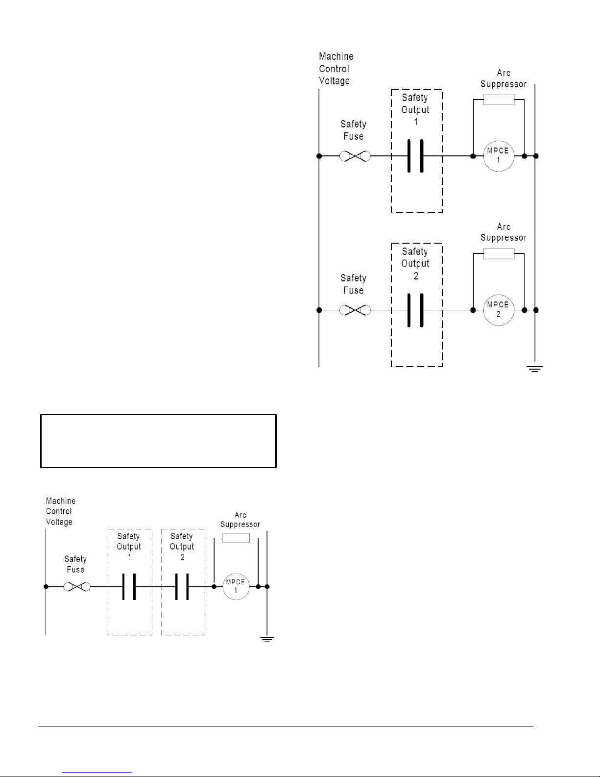
• Normal Risk Machine - These usually have a single
MPCE. In this case, both normally-open safety outputs
should be used together, as shown in Figure 1.
• High Risk Machines - These should have 2
MPCE’s. In some countries, it is customary for both
MPCE’s to operate in the same mode. In this case,
each of the normally-open (NO) outputs controls a
single MPCE. See Figure 2 for an illustration of this
type of interface. Any additional output contacts can
be used as a monitor, e.g., as an input to a PLC.
To protect the contacts of the safety output relays
from the effects of switching inductive loads, an
appropriately rated power factor correction device
must be installed for the MPCE coils. Figures 1 and 2
show ‘Arc Suppressors’ used for this purpose. They
must not be fitted across the safety relay contacts.
Arc Suppressors are user-supplied.
CAUTION
Suppressors must not be connected
across safety relay contacts.
Figure 1 - Interfacing a Machine with 1 MPCE
Figure 2 - Interfacing a Machine with Dual
Identical MPCE’s
3. Electrical Connections
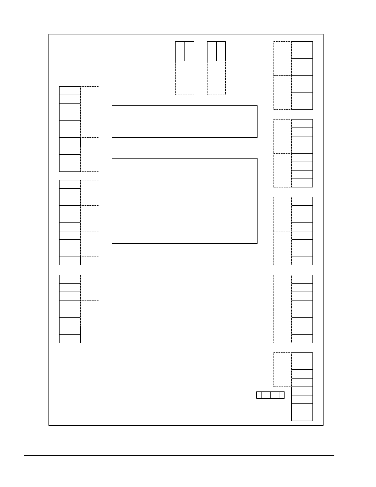
The C6 Controller has eight internal block connectors:
• Mat 1 / Guard 1
• Mat 2 / Guard 2
• Mat 3 / Guard 3
• Mat 4 / Mat 5
• Mat 6
• Safety O/P 1 / Safety O/P 2 / Monitor O/P 1
• Monitor O/P 3 / Monitor O/P 4 / Monitor O/P 5
• Monitor O/P 5 / Monitor O/P 6
Each terminal is mechanically suitable for (1) 2.5mm
(14AWG) wire. Crimped ferrules or tinning must be
used on all standard conductors.
Note: All unused mat inputs must be linked out
using jumper wires in order for the controller to
operate (see the sensor wiring diagram, figure 4,
for link outs). Unused light curtain inputs do not
need to be linked.
The exact wiring requirements are at the discretion of
the installer and depend to a large extent on the siting
of the various control elements, Generally, it is
recommended that high voltage cables be routed
away from low voltage cables.
TAPESWITCH CORPORATION Phone: 631-630-0442
100 Schmitt Boulevard 4 Fax: 631-630-0454
Farmingdale, New York 1735 www.tapeswitch.com
Page 5
Release 08/2007 Ver. 2.0 Technical Manual: C6 Multifunction Interface Controller
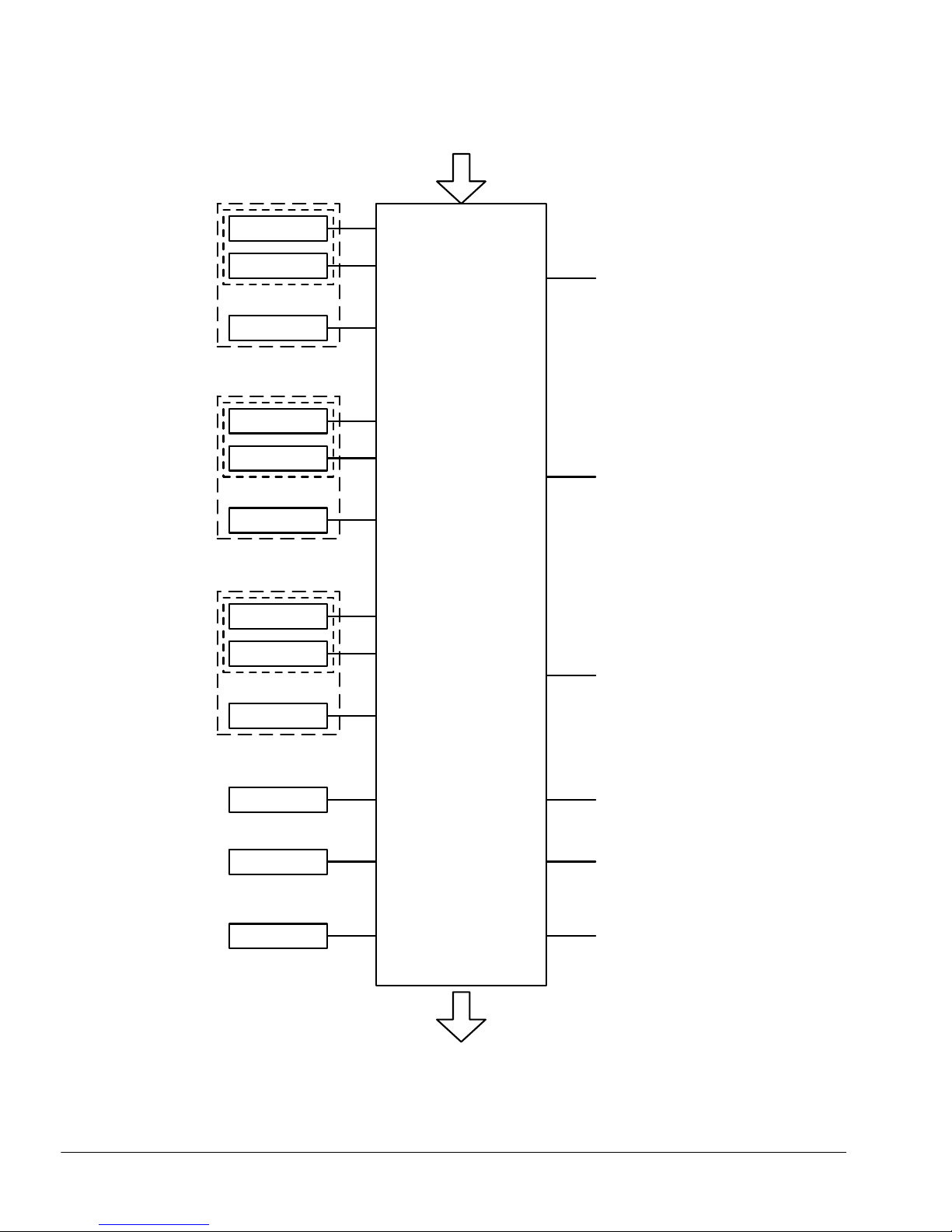
Figure 7 shows the System Block Diagram for the C6
Controller.
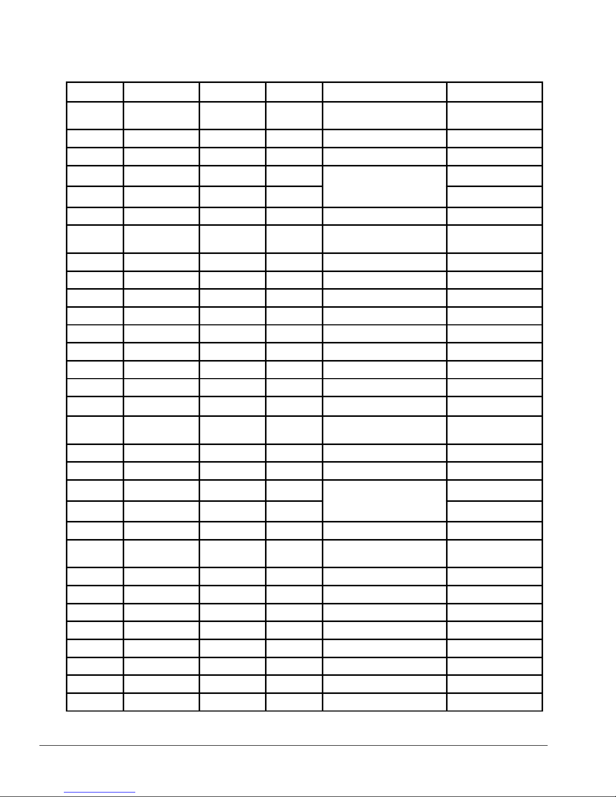
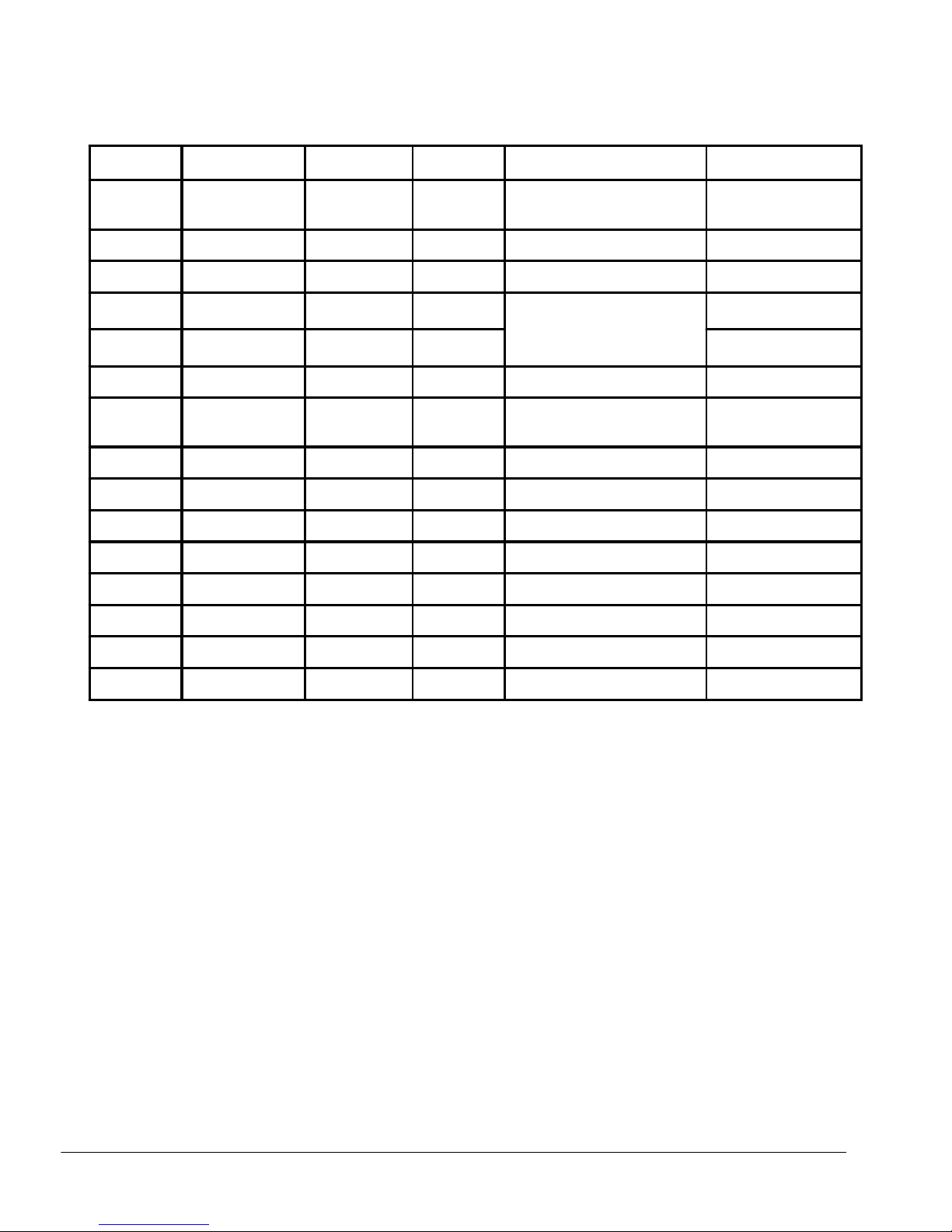
For light curtain installations the Wire Run List (WRL),
Figure 8, will give the proper terminal numbers and
associated functions for the cabling between the BSeries sensing unit (emitter and receiver) and the C6
Control Unit. Be sure to observe the color coding
shown to assure proper operation. The cables for the
interface between the B-Series Sensing Unit (emitter
and receiver) and the C6 Unit are ordered separately.
The emitter cable has five conductors with a black
insulation jacket. The receiver cable has eight
conductors with a black insulation jacket. The cables
will only mate to the proper component of the sensing
unit.
3.1 Reset, Manual/Automatic
The C6 is configured from the factory preset as an
auto reset controller and the output contacts will
resume their original states automatically once the
activated sensor is cleared (i.e., person / object is
removed from the safety mat). For applications where
a manual reset is required, the C6 has P.C. Board
mounted jumpers that change the reset function of a
particular zone from auto reset to manual reset. This
can be accomplished by removing the jumper for the
zone you want changed. This manual reset function is
available on all 6 zones. When a zone is in the
manual reset mode, a Manual Mode Amber indicator
light on the front panel will be illuminated to indicate
the zone that is in manual reset. When the sensing
device is activated, the output contact will remain
open until the sensing device is clear and the
controller is manually reset by the key switch.
In addition to the Amber Manual Mode indicator
lamps, the front panel also has Green lamps that
indicate Output On and Red lamps that indicate
Output Off.
3.2 Pressure Sensitive Sensor(s) Connection
Connect the sensor cables to the C6 Control Unit in
accordance with the Sensor Connection Wiring
Diagram, taking particular care that there are no stray
strands which could cause a short between the
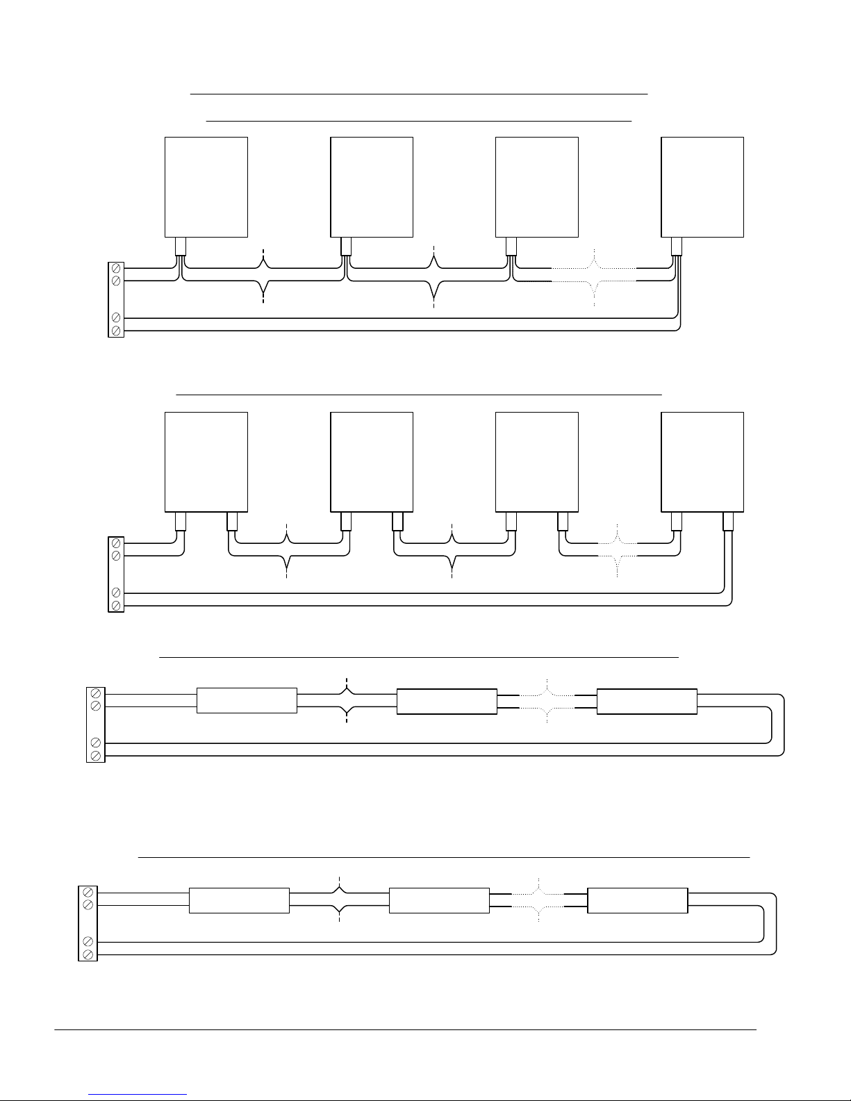
adjacent terminals. A number of sensors can be
connected in series. See Figure 6 for details and
limitations. When connecting a number of sensors in
series, the C6 Controller treats these “combined”
sensors as a single sensor. When any one of these
sensors is actuated the output relays de-energize.
3.3 Mechanical
The metallic enclosure has six knockouts capable of
accepting standard conduit fittings. It is recommended
that any high voltage connection made to the C6
control Unit be made with suitable cabling and/or
conduit protections. The connection between the C6
and the B-Series Sensing Unit (emitter and receiver)
are non-hazardous low voltage signals and additional
protection of these cables is not necessary. It is
recommended that suitable fitting or cable grips be
used to maintain the moisture integrity of the
installation. It is also recommended to separate the
low voltage connections from the high voltage
connections. Local electrical codes should be
observed.
3.4 Power Connection
The power supply P.C. Board is mounted to the inside
of the metal enclosure door. The power supply is
designed to accommodate an input voltage range of
88 to 132 VAC and 176 to 264 VAC and an input
frequency range of 47 to 63Hz. Along the bottom
edge of the P.C. Board is a terminal block CN1.
Terminal block CN1 is the input power connection
point for the C6 Controller. Supplied with the C6
Controller is a mating terminal block connector and
pins to which the input power wires will be crimped to
and inserted into the terminal block. Once the terminal
block connector is assembled, it can be attached to
the P.C. Board terminal block by inserting the
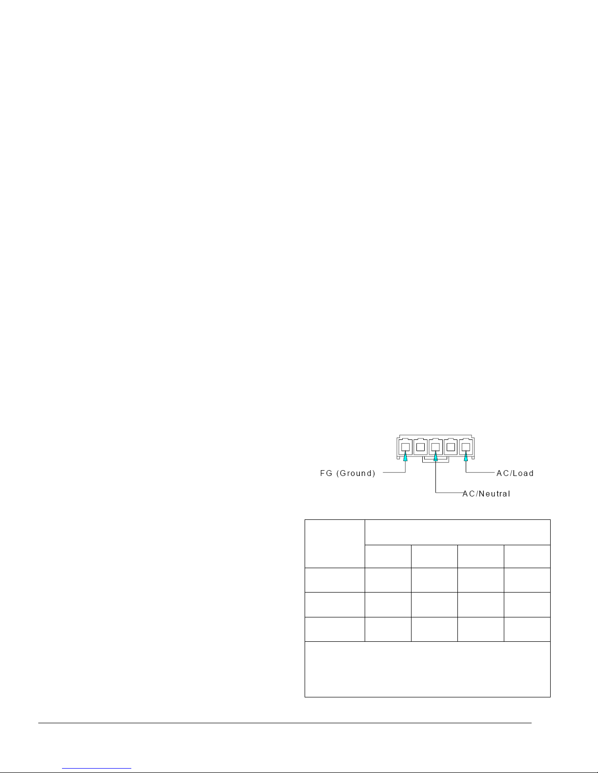
connector into the terminal block, CN1. See Figure 3
below.
Figure 3 - Connector
SENSOR
TYPE
Mats
(single lead)
Mats
(dual lead)
Edges Smooth 1 Smooth 2 Ribbed 1 Ribbed 2
All unused mat inputs must be linked out using jumper wires in
order for the controller to operate, i.e. LINK A-B LINK C-D.
If you are connecting a Guard to Guard #1 NO CONNECTIONS
should be made to Mat #1. Same holds true for Guard #2 and
Guard #3.
White 1 White 2 Black 1 Black 2
Figure 4 - Sensor Wiring Diagram
SENSOR CONNECTION
A B C D
Red White Black Yellow
TAPESWITCH CORPORATION Phone: 631-630-0442
100 Schmitt Boulevard 5 Fax: 631-630-0454
Farmingdale, New York 1735 www.tapeswitch.com
Page 6
Release 08/2007 Ver. 2.0 Technical Manual: C6 Multifunction Interface Controller
-
+
24 V D C
RES ET
C T R
N /C
N / O
C T R
N /C
N / O
Sa fe ty
O/P 1
Sa fe ty
O /P 2
C 6 C O N T R O L L E R
C O N N E C T IO N S
C T R
N /C
N / O
C T R
N /C
N / O
C T R
N /C
N / O
C T R
N /C
N / O
Mo nitor
O/ P 1
A ll u n use d m at inp u ts m ust b e lin ke d o ut
us in g jum pe r w ire s in o rd e r for th e c o n tro lle r
Mo nitor
O/ P 2
to o p era te , i.e .,
L IN K A -B
L IN K C -D
If yo u a re c o nne c t ing a G ua rd to G uard #1
Mo nitor
O/ P 3
N O C O N N E C TIO NS s h ou ld b e m ad e to M at
#1 . S am e ho ld s true fo r G uard #2 a n d
G u ard #3 .
Mo nitor
O/ P 4
M 1A
MAT 1 GUA R D 1 MAT 2 MAT 3 MAT 4 MAT 5GUA R D 2 G U ARD 3
M 1B
M 1C
M 1D
+2 4
C O M
G 1A
G 1B
M 2A
M 2B
M 2C
M 2D
+2 4
C O M
G 2A
G 2B
M 3A
M 3B
M 3C
M 3D
+2 4
C O M
G 3A
G 3B
C T R
N /C
N / O
C T R
N /C
N / O
Mo nitor
O/ P 5
M 4A
M 4B
M 4C
Mo nitor
O/ P 6
M 4D
M 5A
M 5B
M 5C
M 5D
56421
PR OGR AM
JU MP ER S
RE SET
3
MA NU AL
M 6A
MAT 6
M 6B
M 6C
M 6D
AU TO/
Figure 5 - PC Board Terminal Block Locations
TAPESWITCH CORPORATION Phone: 631-630-0442
100 Schmitt Boulevard 6 Fax: 631-630-0454
Farmingdale, New York 1735 www.tapeswitch.com
Page 7
Release 08/2007 Ver. 2.0 Technical Manual: C6 Multifunction Interface Controller
INTERCONNEC T DIAGRAMS, D A IS Y C H A INED /SER IES CONNEC T ION
Multiple M ats w ith 4 C o n ductor Stand ard Color C o ded Lea d W ire
MAT 1 MAT 2 MAT 3 MAT N
C
A
D
B
BL ACK
RE D
YE LLO W
WHITE
WHITE
RE D WHITE
NO T E: Maxim um Num b er o f M ats Limite d to 100 S qu are Feet
WHITE
RE D
YE LLO WYE LLO WYE LLO W
BL ACKBL ACKBL ACK
RE D
Multiple M ats w ith O ptiona l 2 Cond u cto r Standard Color Code d L ead Wire
MAT 1 MAT 2 MAT 3 MAT N
C
A
D
B
BL ACK # 1
WHITE # 1
BL ACK # 2
WHITE # 2
BL ACK
WHITE
BL ACK BL ACK
WHITE
WHITE
BL ACK BL ACK
WHITE
BL ACK
WHITEWHITE
C
A
D
B
Multiple Sens in g E d ges, B umpers and Ribbon Switch es with Color Cod e d W ire
BL A CK #1
WHIT E #1
BL A CK #2
WHITE #2
Ed ge/sen sor 1
Ed ges and B um p ers Ca n Be O rd er ed w ith L ead W ire E x iting B oth En ds to Facilita te E asy S eries C onn ec tio n
BL K
WHT
BL K BL K BL K
Ed ge/sen sor 2 Ed ge/sen sor N
WHT WHTWHT
WHIT E
BL A CK
NO T E: Maxim um Num b er o f E d ges, B umpe rs , and Ri bb on Sw itch es L im ited to 200 Feet
Multiple Sen sin g E d ges, Bumpers and Ribbon Sw itche s w ith N o n-C o lor C oded Zip C ord W ire
C
A
D
B
RIBBED #1
Ed ge/sen sor 1 Ed ge/sen sor NEd ge/sen sor 2
SM OO T H #1
RIBBED #2
SM OO TH #2
RIB
SM O
RIB
SM O SM OS M O
RIB RIB
SM O O TH
RIBBE D
Figure 6 - Multiple Sensor Connections
TAPESWITCH CORPORATION Phone: 631-630-0442
100 Schmitt Boulevard 7 Fax: 631-630-0454
Farmingdale, New York 1735 www.tapeswitch.com
Page 8
Release 08/2007 Ver. 2.0 Technical Manual: C6 Multifunction Interface Controller
Power Input
Emitter # 1
Receiver # 1
or
Sensor #1
W1
W2
Monitor Output #1
Zone 1
Zone 1
Emitter #2
W1A
Receiver #2
or
W2A
Sensor #2
Zone 2
C6
Multifunction
Controller
Monitor Output #2
Zone 2
Emitter #3
W1B
Receiver #3
or
Sensor #3
Zone 3
W2B
Monitor Output #3
Zone 3
Sensor #4
Zone 4
Monitor Output #4
Zone 4
Sensor #5
Zone 5
Monitor Output #5
Zone 5
Sensor #6
Zone 6
Monitor Output #6
Zone 6
Safety Outputs to
Machine Controls
Figure 7 - System Block Diagram
TAPESWITCH CORPORATION Phone: 631-630-0442
100 Schmitt Boulevard 8 Fax: 631-630-0454
Farmingdale, New York 1735 www.tapeswitch.com
Page 9
Release 08/2007 Ver. 2.0 Technical Manual: C6 Multifunction Interface Controller
WIRE RUN LIST for the C6 Multifunction Controller
Up to Three Light Curtain Configurations
Cable # Cable Type Color Code Function From Light Curtain #1 C6 to Guard #1
RKT5-612/XX
5 Pin Quick Disconnect
Emitter
W 1 " Brown +24 VDC 1 +24
W 1 " White OV DC 2 COM
W 1 " Blue Test Out
TWIST PAIR TOGETHER
W 1 " Black Test In No Connection
W 1 " Gray Ground 5 COM
RKT8-09/XX
W 2 " White OV DC 1 COM
W 2 " Brown 24 VDC 2 +24
W 2 " Green Ground 3 COM
W 2 " Yellow Output 1 4 G1A
W 2 " Gray Output 2 5 G1B
W 2 " Pink Data (-) 6} Isolate 6 & 7 No Connection
Black & Blue Wire
Receiver
8 Pin Quick Disconnect
No Connection
W 2 " Blue Data (+) 7} Isolate 6 & 7 No Connection
W 2 " Shield Ground 8 COM
Cable # Cable Type Color Code Function From Light Curtain #2 C6 to Guard #2
RKT5-612/XX
W 1 A " Brown +24 VDC 1 +24
W 1 A " White OV DC 2 COM
W 1 A " Blue Test Out
W 1 A " Black Test In No Connection
W 1 A " Gray Ground 5 COM
RKT8-09/XX
W 2 A " White OV DC 1 COM
W 2 A " Brown 24 VDC 2 +24
5 Pin Quick Disconnect
TWIST PAIR TOGETHER
8 Pin Quick Disconnect
Emitter
No Connection
Black & Blue Wire
Receiver
W 2 A " Green Ground 3 COM
W 2 A " Yellow Output 1 4 G 2 A
W 2 A " Gray Output 2 5 G 2 B
W 2 A " Pink Data (-) 6} Isolate 6 & 7 No Connection
W 2 A " Blue Data (+) 7} Isolate 6 & 7 No Connection
W 2 A " Shield Ground 8 COM
Figure 8 - Wire Run List
TAPESWITCH CORPORATION Phone: 631-630-0442
100 Schmitt Boulevard 9 Fax: 631-630-0454
Farmingdale, New York 1735 www.tapeswitch.com
Page 10
Release 08/2007 Ver. 2.0 Technical Manual: C6 Multifunction Interface Controller
WIRE RUN LIST for the C6 Multifunction Controller
Up to Three Light Curtain Configurations (continued)
Cable # Cable Type Color Code Function From Light Curtain #3 C6 to Guard #3
W 1 B " Brown +24 VDC 1 +24
W 1 B " White OV DC 2 COM
RKT5-612/XX
5 Pin Quick Disconnect
Emitter
W 1 B " Blue Test Out
TWIST PAIR TOGETHER
W 1 B " Black Test In No Connection
Black & Blue Wire
No Connection
W 1 B " Gray Ground 5 COM
W 2 B " White OV DC 1 COM
W 2 B " Brown 24 VDC 2 +24
W 2 B " Green Ground 3 COM
RKT8-09/XX
8 Pin Quick Disconnect
Receiver
W 2 B " Yellow Output 1 4 G 3 A
W 2 B " Gray Output 2 5 G 3 B
W 2 B " Pink Data (-) 6} Isolate 6 & 7 No Connection
W 2 B " Blue Data (+) 7} Isolate 6 & 7 No Connection
W 2 B " Shield Ground 8 COM
Figure 8 - Wire Run List (continued)
TAPESWITCH CORPORATION Phone: 631-630-0442
100 Schmitt Boulevard 10 Fax: 631-630-0454
Farmingdale, New York 1735 www.tapeswitch.com
Page 11

Release 08/2007 Ver. 2.0 Technical Manual: C6 Multifunction Interface Controller
4. Operational Sequence and LED
Status Description
Note: The LEDS on the C6 provide status indication
for the output state of the safety relay in relation to
each of the six zones. The LEDS also indicate what
zones are in Manual Mode.
RESETTING OPTIONS
The C6 Interface can be configured for a manual
(latched) reset or automatic reset. In the manual reset
mode the safety outputs will go to the “off” state once
the light curtain is obstructed and remain in the “off”
state until the obstruction is removed and the reset
key switch is activated. Once this reset sequence is
followed the safety outputs will resume the “on” state.
In the automatic reset mode the safety outputs will
follow the state of the light curtain or sensor (i.e., light
curtain clear: outputs “on”, light curtain obstructed:
outputs “off”.) The following operational sequence will
be described for both reset options.
4.1 Manual Reset
When power is first applied to the C6 Controller:
1.) The amber Manual Mode lights (only for the zones
in Manual Mode) will be illuminated and no other
lights will be illuminated until the key switch reset is
initiated.
2.) Once the key switch reset is initiated, the six green
LEDS (zones 1 through 6) will illuminate. This is
provided the system is properly wired, no faults exist
and the sensors are clear and or the B-Series sensing
units (emitter and receiver) have power and are
properly aligned. All safety relay outputs will be in the
“on” state. The green LEDS on the C6 Controller
indicate that all the zone safety outputs from the
sensors and/or B-Series sensing units are functioning.
All of the green LEDS must be illuminated in order for
the safety output relays to be in the “on” state.
3.) These outputs will remain “on” until a zone(s)
sensor(s) is activated and/or the light curtain(s) is
obstructed, faulty or misaligned. If an activation and/or
obstruction occurs in a zone(s), the green LEDS
(Output On) will go off and remain off and the red
(Output Off) light(s) will flash. The green LEDS will
remain off (even if the sensors and or light curtain is
cleared) until the key switch reset is applied.
4.) Once the reset is applied, the flashing red light(s)
for the activated zone(s) will turn off and the six green
LEDS will illuminate and the safety output relays will
also go to the “on” state.
4.2 Automatic Reset
When power is first applied to the C6 Controller:
1.) Power is automatically applied to sensors and or
light curtains (emitters and receivers) and if the
system is properly connected and aligned (see the
following wiring information) and the sensing units are
clear with no faults, the C6 Controller should have six
green “Output On” LEDS illuminated.
Note: When the C6 Controller is set in the Automatic
Reset Mode, the Manual Mode amber lights will NOT
be illuminated.
These green LEDS indicate the output status (zones
1 through 6) is “on” and the redundant output safety
relays are in the “output on” state (normally open or
normally closed depending on wiring hook-up choice).
The outputs will remain “on” until an obstruction or
fault occurs in any of the sensing units and/or light
curtains (emitter or receiver pairs). When a sensing
unit zone is activated the corresponding red LED
“Output Off” will illuminate and flash. These LEDS
indicate the output status (both redundant safety
outputs are off) and also identify which sensing zone
has been activated.
Zone 1 Red flashing indicates that sensing unit one
has been activated and Zone 2 Red flashing indicates
that sensing unit two has been activated, etc. For the
zones, which are not activated, the Green LED output
status will remain lit steady. It is important to note that
the Green LED status indicators may be illuminated,
however, the redundant safety outputs may actually
be off as a result of the other zone sensing unit being
activated. This is designed to assist the user as to
which sensing unit zone has caused the output to go
to the off state. The outputs will remain open until the
sensor and or light curtain is clear. The outputs follow
the state of the sensor and or light curtain and reset
AUTOMATICALLY without any operator intervention.
It is important to note the C6 does not distinguish
between a light curtain fault, obstruction, misalignment
or improper wiring. All of these conditions cause the
C6 to respond as if the sensor is activated and or the
light curtain is obstructed and the redundant safety
outputs will be in the off state.
TAPESWITCH CORPORATION Phone: 631-630-0442
100 Schmitt Boulevard 11 Fax: 631-630-0454
Farmingdale, New York 1735 www.tapeswitch.com
Page 12
Release 08/2007 Ver. 2.0 Technical Manual: C6 Multifunction Interface Controller
4.3 Monitor Output
Non-safety monitor outputs are also provided for all
six zones. These outputs can be configured either
normally open or normally closed. The monitor
outputs should be wired in such a way to indicate the
status of both safety output relays. As an example, if
both safety outputs are connected as normally open
(contacts closed when the mat and or light curtain is
clear) the monitor relay output should be wired as
normally closed. Therefore, when the safety outputs
are open (contacts open when the mat and or light
curtain are activated), the monitor outputs will be
closed. These outputs can be used for non-safety
related functions such as displays and status
indications. It must not be used for safety related
machine control and switching functions.
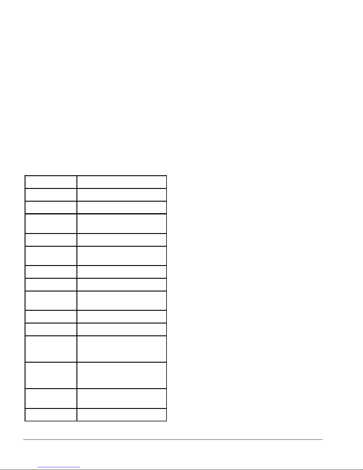
C6 - TECHNICAL SPECIFICATIONS
MODEL STYLE C6 Multifunction Controller
Part Number
Supply Voltage
Power
Consumption
Enclosure Type
Protection Rating
Weight
Sensor Wiring
Reset Mode
Outputs Relays
Output Contacts
Monitor Output
Applications
Operating
Temperature
Response Time
0480
110-240 VAC 50/60 Hz or 24 VDC
30VA TYPICAL
Metal Wall Mount
NEMA 1 Standard / IP10, NEMA
12 Optional / IP52
9.5 lbs. (4.3 kg)
Fail-Safe
Automatic (supplied) or
Manual Reset or Combination
Forced Guided Safety Relays
6.0A @ 240 VAC Resistive Load
Non-Safety 6 X (N/O or N/C)
Selectable, 10A @ 250 VAC
Resistive
Light curtains, ribbon switches,
sensing edges/bumpers, switching
mats
0 oC to 50 oC
10ms
4.4 Printed Circuit Board LEDS
On the main printed circuit board, adjacent to the
sensor/ light curtain terminal blocks are a series of red
LEDS. The LEDS are placed in pairs to coincide with
the location of the inputs of the sensors and light
curtains. The purpose of these LEDS is to indicate the
status of the sensing device that is being used. If both
LEDS are illuminated, this indicates that the sensing
device is open or clear. If both LEDS are off, this
indicated that the sensing device is closed or blocked.
If only one of the LEDS is illuminated, this indicates
that there is a problem with the sensor wiring or
sensor (mat, edge, and bumper, etc.). In a light curtain
application a single LED will indicate that one of the
receiver outputs is inoperative or not connected.
TAPESWITCH CORPORATION Phone: 631-630-0442
100 Schmitt Boulevard 12 Fax: 631-630-0454
Farmingdale, New York 1735 www.tapeswitch.com
Page 13
Release 08/2007 Ver. 2.0 Technical Manual: C6 Multifunction Interface Controller
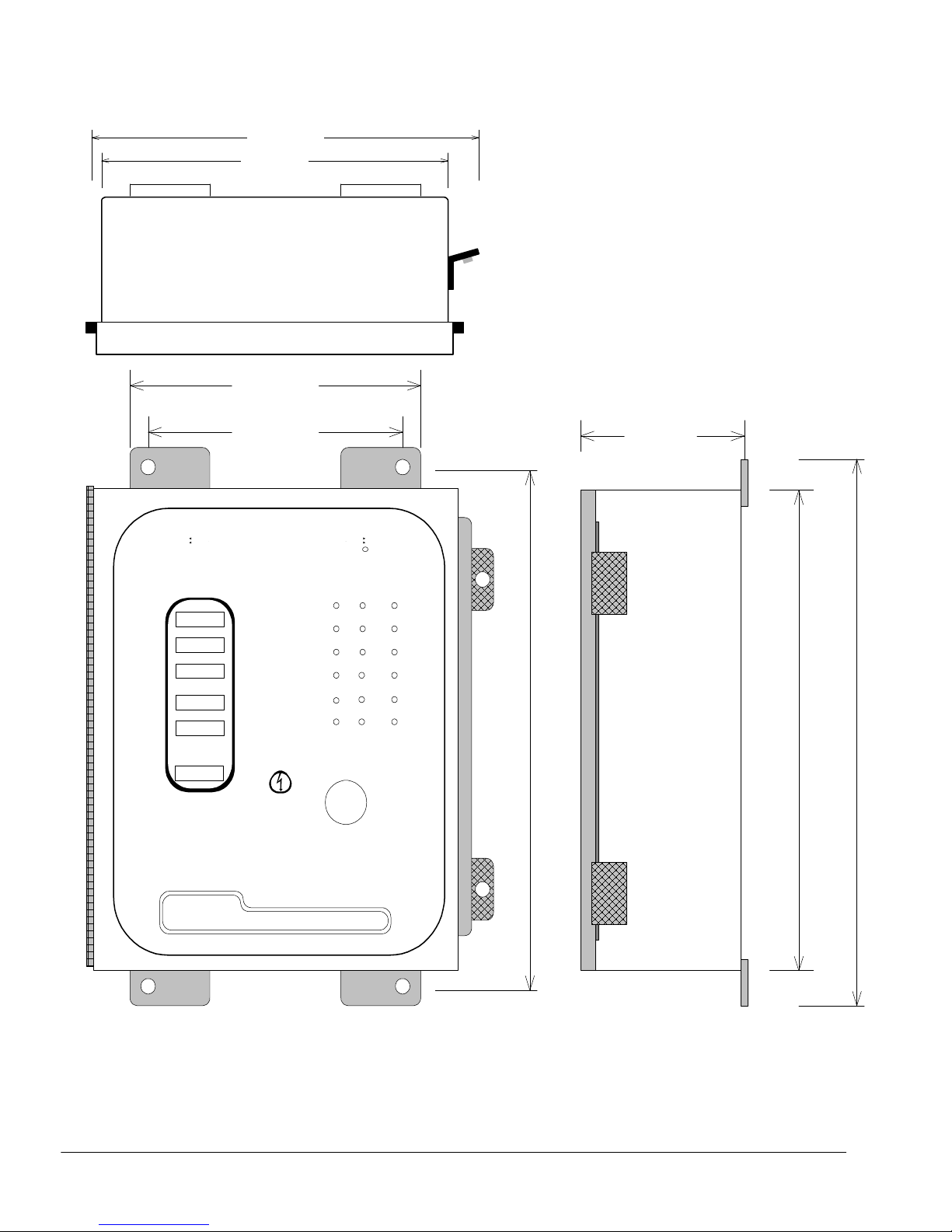
5. Outline Drawing
8.9 4" (2 27 m m )
8 " ( 20 3m m)
7" (1 78mm)
6" (1 52mm)
GGGG UUUU A R D S T A R
A R D S T A R
Typ e No :
C6
Ser ial No:
Sup ply V oltag e:
110 -240V AC
50/6 0 HZ
Pow er
Con sump tion:
30V A TYP ICAL
Outp ut C ontac ts:
4.0A@ 24 0VAC
RES ISTIV E LO AD
Safe ty Sys tem
Res ponse Time
Equa ls
Sen sing U nit
Res ponse Time
+1 0M S
A R D S T A RA R D S T A R
ZO NE 1
ZO NE 2
ZO NE 3
ZO NE 4
ZO NE 5
ZO NE 6
by Tapesw itch
MANU AL
OUTP UT
MOD E
ON
RESE T
B SERIES
C 6
C6
M U L T I F U N C T IO N C O N T R O L E R
M ultifunction Controller
Syste m
Ta pe sw itch
COR PORA TION
100 Schm itt Blvd. , Farmi ngdale, NY 11 735
Toll Free: 1 -800-2 34-827 3
4.1 2" (1 05mm )
R
OUTP UT
OFF
10 .75"
(27 3mm)
10"
(25 4m m)
11 .5"
(29 2m m)
C o ntrolle r
TAPESWITCH CORPORATION Phone: 631-630-0442
100 Schmitt Boulevard 13 Fax: 631-630-0454
Farmingdale, New York 1735 www.tapeswitch.com
 Loading...