

Page 1
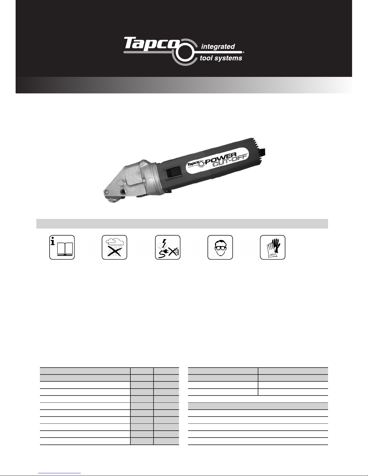
OPERATIONS MANUAL
Operating Instructions for the Dräco
Metal-Shear SD5-1 and S1001N-1
To avoid any disturbance, please read the following instructions:
FOR YOUR SAFETY:
Valid 10/2002
1 2 3 54
1 Safe operation of this machine is only possible when the
operating instructions and the safety precautions are
read completely and the instructions contained therein
are strictly observed.
2 The machine must not be used or operated in a damp or a
wet environment.
3 Always inspect the cable and plug before using machine.
Damage must only repaired by a qualified professional. The
plug should only be placed into the main socket when the
machine is in the off position.
4+5 Always wear protective goggles, protective gloves and
heavy-duty shoes when working.
For further notes on safety please refer to the red safety leaflet
enclosed in the tool box.
l Do not carry the machine by the cable.
l Always remove the plug from the power supply socket
before carrying out any work on the machine, during work
interruptions or when not using the machine.
l Always place the cable to the rear, away from the machine.
l Apply the machine to the sheet metal only, when switched on.
l Always provide for secure footing when working.
l Firmly clamp the work piece if it does not remain stationary
from its own weight.
l The knife should not rub on the jaws as there is a possible
danger of breaking the cutting tool.
l Do not exceed the maximum allowable material thickness,
especially when cutting over double folded joints or welded
seams.
F
DRÄCO metal shears SD5-1 S1001N-1
max. cutting capacity
steel 400 N/mm² mm/ga. 1.0 / 19 1.3 / 18
stainless steel 600 N/mm² mm/ga. 0.7 / 21 1.0 / 19
stainless steel 800 N/mm² mm/ga. 0.4 / 24 0.7 / 21
aluminium 250 N/mm² mm/ga. 1.5 / 16 2.0 / 14
tightest radius mm/ga. 50 100
working speed ± m/min 5-9 5-9
strokes min
-1
3900 3900
motor capacity Watt 300 300
weight kg 1.6 1.6
all units are ready to use
SD5-1 S1001N-1
spare parts spare parts
knife 01011 knife 01001
set of jaws BG13574/1 set of jaws BG10600
knife-pin set BG12555
optional accessories
metal-box 18000
adjustable guide S/01 up to 100mm 10059
adjustable guide S/01 up to 250mm 10060
adjustable guide S/01 up to 500mm 10061
support roller BG10076
BG=Set other voltages available
Page 2
2
WWW.TAPCO-EUROPE-TOOLS.COM
SPARE PARTS FOR SD5-1 AND S1001N-1
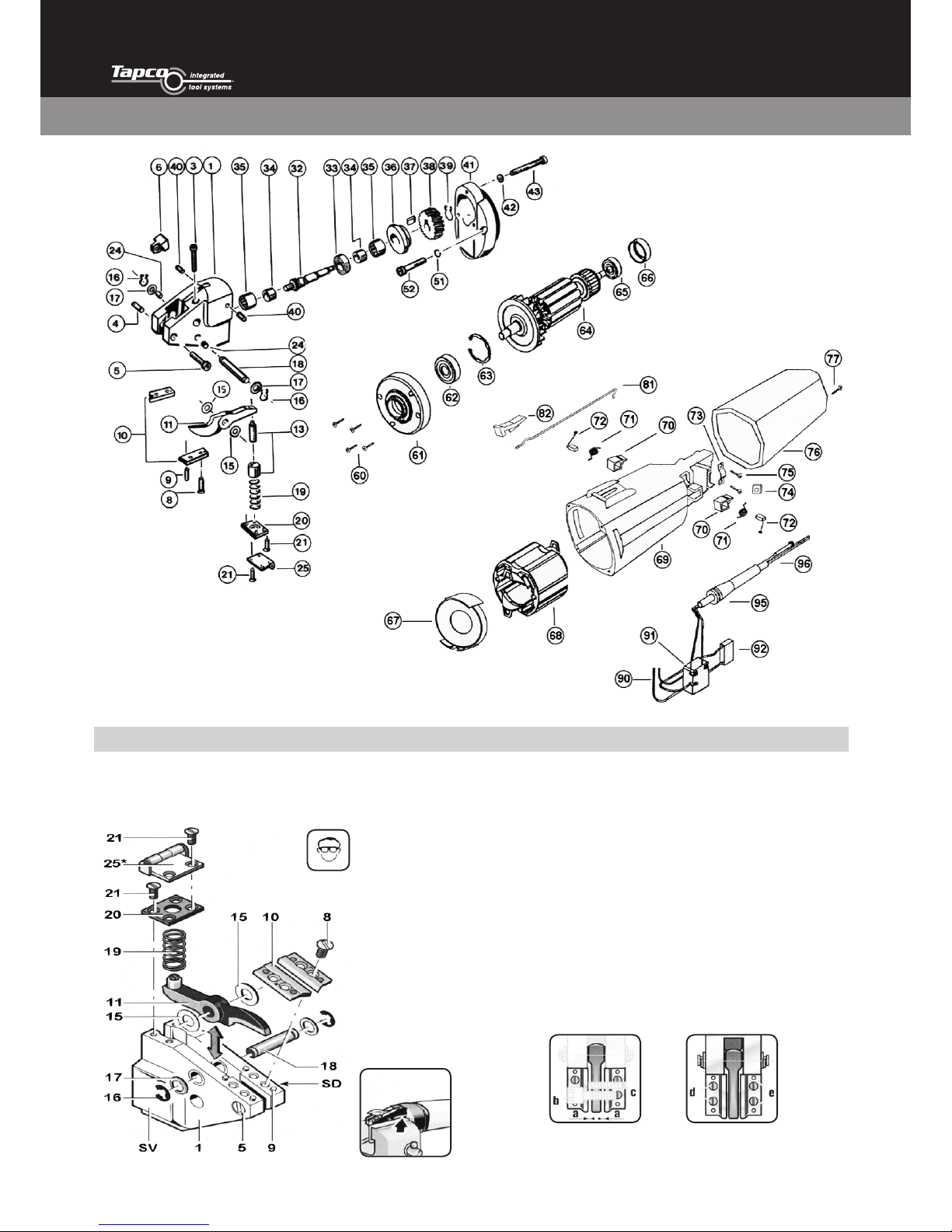
SERVICE TIPS
Before working on machine disconnect from power supply by
removing plug from socket.
Wear protective glasses!
1. One drop of oil between knife (11) and head-casting (1) keeps
the spacing shims (15) in place.
2. Dismantle Spring cover (20) and take spring out (19).
3. Take circlip (16) and washer (17) off.
4. Push knife pin (18) out of casting.
5. Take knife out of housing
6. Attention, do not exchange the spacing shims (15).
7. Place the knife inside the housing feed shims in on one side
and push knife pin (18) into housing up to the middle of the
knife.
8. Feed the shims on the other side of the knife.
9. Push knife pin in completely, and secure washer (17) and
circlip (16) again.
10. Assemble spring (19) and spring cover (20).
11. Between the knife (11) and the jaws (10) should be some
distance, approximately 0.1 mm on each side. Knife (11) must
be placed tight in the head casting.
12. Adjustment for the play between the jaws. (a): 0.1 to 0.15 mm.
* optional
13. If knife has contact with the jaws on both sides, adjust with
screws in the head casting. If a burr is on the material, adjust
the space between the knife and the jaws.
Page 3
3
WWW.TAPCO-EUROPE-TOOLS.COM
SPARE PARTS FOR SD5-1 AND S1001N-1
Pos. Order Pos. Order
No. No. Description Pcs. No. No. Description Pcs.
1 BG10500 Head casting (SD5, S1001N) 1 42 81249 Securing washer 3
1-52 10057 Shear head S1001N cpl. assembled, without
motor
1 43 81012 Flat fillister head screw 3
1-52 10557 Shear head SD5 cpl. assembled, without
motor
1 51 81243 Securing washer 2
3 81263 Hex socket screw 1 52 81181 Hex socket screw 2
4 81089 Spacing-block set screw 1 60-96 16060 Motor cpl. 115 V USA/CDN 1
5 81272 Flat fillister head screw 1 60-96 16000 Motor cpl. 230 V (VDE) 1
4-6 BG10002 Spacing Block Pos. 4-6 1 60-96 16000 CH Motor cpl. 230 V (CH) 1
6 10002 Spacing Block 1 60-96 16000 I Motor cpl. 230 V ( I ) 1
8 81286 Flat Head Screw 4 60 16013 PT-Screw 4
9 81248 Pin 4 61 16015 Bearing end plate 1
Knife for S1001N cutting (width: 4mm) 62 10038 Ball bearing 1
11 01001 Knife 1001 Standard up to 1.3mm 1 63 16014 Circlip 1
01001HM Knife 1001 carbide tipped 1 64 16059 Armature 115 V 1
10111 Knife for radius cutting 1001/01: 0.75mm 1 64 16009 Armature 230 V 1
10110 Pattern Knife up to 0.5mm 1 65 10040 Ball bearing 1
8-10 BG10600 Jaws for S1001N SET Pos. 8-10 1 66 16029 Insulating ring 1
10600HM Jaws for S1001N carbide tipped 1 67 16030 Ventilation cover 1
Knife SD5 for SD5 cutting (width: 5mm ! ) 1 68 16007 Field / Stator 230 V 1
11 01011 Knife SD5 1 68 16057 Field / Stator 115 V 1
8-10 Set of jaws SD 5 Pos. 8-10 69 16039 Housing 1
13 35566 Knife Lock ring with Adjusting Screw 1 70-71 BG16035 Brush Holder and Spring 2
15 BG12400 Spacing shims 1 72 16002 Carbon Brush 2
16 81275 Circlip 1 73 16021 Cable collar 1
17 81072 Washer 1 74 16019 Hex. Nut 1
18 12500 Knife pin 2 75 16020 Screw 2
15-18 BG12555 Knife pin set Pos. 15-18 2 76 16036 Switch Cover 1
19 12200 Spring 1 77 16018 Screw 1
19-21 BG12300 Spring cover Pos. 19-21 1 81 16032 Switch Connection Lever 1
20 12300 Spring cover 1 82 16033 Switch Knob 1
21 81285 Flat Head Screw 1 90 16017 Connection Wire 2
24 17900 Knife pin bushing Ø 10mm 1 91 16031 Switch 1
24 17911 Knife pin bushing Ø 11mm 4 92 16005 Condensator 1
25 BG10076 Support roller 2 95 16022 Rubber-Sleeve 1
32-39 BG10058 Drive Shaft cpl. Assembled Pos. 32-39 2 96 32046 Cable with Plug Europe (VDE) 1
32-34,37+39 BG10004 Eccentric drive shaft Pos. 32-34,37+39 1 96 20260 Cable with plug CH (SEV) 1
32 10004 Eccentric drive shaft 1 96 20250 Cable with plug IT 1
33 10250 Ball bearing 1 96 20242 Cable with plug USA/CDN 1
34 10005 Sleeve
35 10300 Needle bearing
35-36 BG10450 Cap for needle bearing Pos. 35-36
37 10006 Key Accessories
38 10007 Gear 1 10059 Adjustable guide S/01 100mm
39 10009 Circlip 1 10060 Adjustable guide S/01 250mm
40 81239 Tap screw 2 10061 Adjustable guide S/01 500mm
41-43, 51+ 52 BG10010 Gear case Pos. 41-43, 51, 52 1 18000 Metal Box (Metal)
Specifications are subject to change for improvement without prior notice.
When ordering spares, please mention order number and voltage.
Dealer address:
Page 4
4
WWW.TAPCO-EUROPE-TOOLS.COM
Recycling raw materials instead of waste
disposal.
Machine, accessories and packaging should be
sorted for environment-friendly recycling.
Item #250309
©2014 Tapco International Corporation
OPERATING INSTRUCTIONS
Tapco Integrated Tools Systems
Unit 32, Tokenspire Business Park, Hull Road, Woodmansey, Beverley, East Yorkshire, HU17 0TB
Tel: +44 (0)1482 880478 | Fax: +44 (0)1482 880678 | [email protected] | www.tapco-europe-tools.com
1. This Power Tool is intended for industrial applications for
cutting sheet metal. Max. capacity is indicated in the technical
data. Do not cut sheet metal through, or along, welding
points, or multi-layer sheets which exceed the max. cutting
capacity. To cut spiral wound tubing 4 x 0.9mm in metal,
models 3514-2 or 3514 -7R must be used.
To Switch ON: Slide the switch (82) forward
To Switch OFF: Slide the switch (82) to the rear.
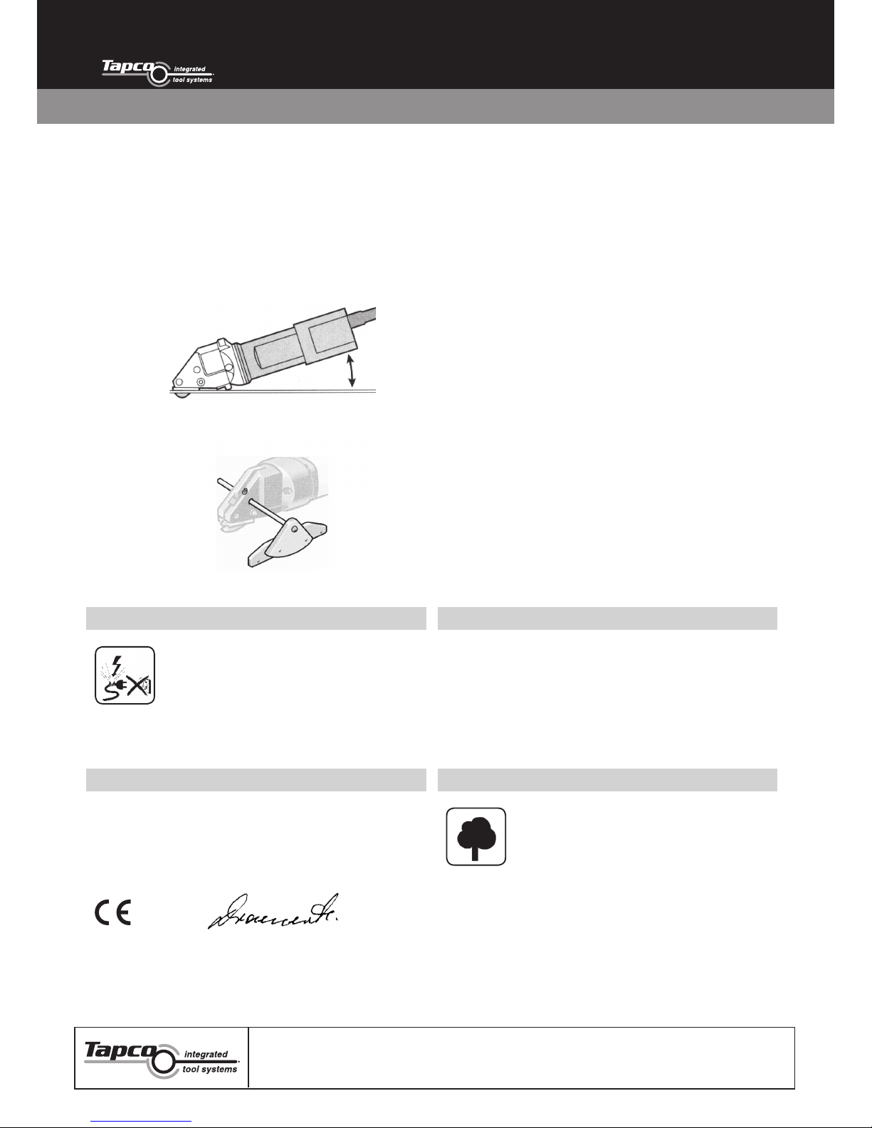
2. The shear must always be guided flat and the best cutting
result is achieved, when the jaws pos. 10 are positioned flat on
top of the material, also when cutting circular cuts.
3. When stopping inside the material, pull metal shear back
straight out of the waste, with motor in operation. If too long,
cut waste off first.
4. Circular cuts, always cut anti-clockwise from right to left. The
outside radius is unlimited.
5. For cutting out curved or inside patterns a 12-14mm hole
must be drilled or punched or a slot should be made to insert
the cutting knife. For square or rectangle cut-outs, drill a hole
between 12-14mm in each corner.
6. A one side cut with the metal shear is possible, a small strip
can be easily cut off without leaving a burr and any distortion
or scratch marks.
7. A template should be manufactured when cutting a multiple
number of the same parts. A cut along the template is
possible without risk of damaging the knife. Front points of
the jaws left and right are used to exactly cut along a marked
line. To cut strips, use adjustable guide S/01. This guide is
infinitely variable due to the hole in the housing and can be
tightened with the set screw. Adjustable guide S/01 can be
supplied in 100mm, 250mm and 500mm lengths.
8. Knife and jaws can be sharpened. After being sharpened or
replaced, the knife, at its lowest point, should protrude the
jaws by approximately 2.5mm. The gap between the knife and
the jaws should be approximately 0.1mm on both sides. For
burr-free cutting, adjust the cutting gap as follows: loosen the
screw, adjust the gap with set screw, to the left narrow, to the
right wide, and tighten screw again. Check gap with a feeler
gauge.
9. If you read these suggestions carefully, any kind of material
can be cut for around 200 working hours before sharpening
the knife and jaws.
10. The material to be cut must always be free of oil or grease.
Adjustable guide S/01
GUARANTEECARE AND MAINTENANCE
Before repairing or any maintenance on
machine, disconnect from power supply by
removing plug from socket. Always keep the
machine and the ventilation slots clean. Oil the
knife pin 18 and knife 11 at regular intervals.
If the machine should happen to fail, despite the care taken in
manufacture and testing, repair should be carried out by an
authorised customer services agent for Dräco power tools.
Dräco tools carry a guarantee of 24 months from date of delivery.
Damage attributable to normal wear and tear, overload or
improper handling will be excluded from the guarantee.
In case of complaint please send the machine, undismantled, to
your dealer or the Dräco Service Centre for electric power tools.
ENVIRONMENTAL PROTECTIONDECLARATION OF CONFORMITY
We declare under our sole responsibility that this product is in
conformity with the following standards:
EC 98/37, EC 93/ 68 EWG, EC 04/108 EC or standardisation DIN EN
ISO 12100-1 , DIN EN ISO 12100-2 , EN 50 144, EN 55 014, CISPR 14-1,
CISPR 14-2, IEC61000-3-2, IEC61000-3-3, IEC 60745-1, IEC 60745-2
09 Draenert
 Loading...