

Page 1

PRO Brake
Operating Instructions
Tapco Products Company
Page 2
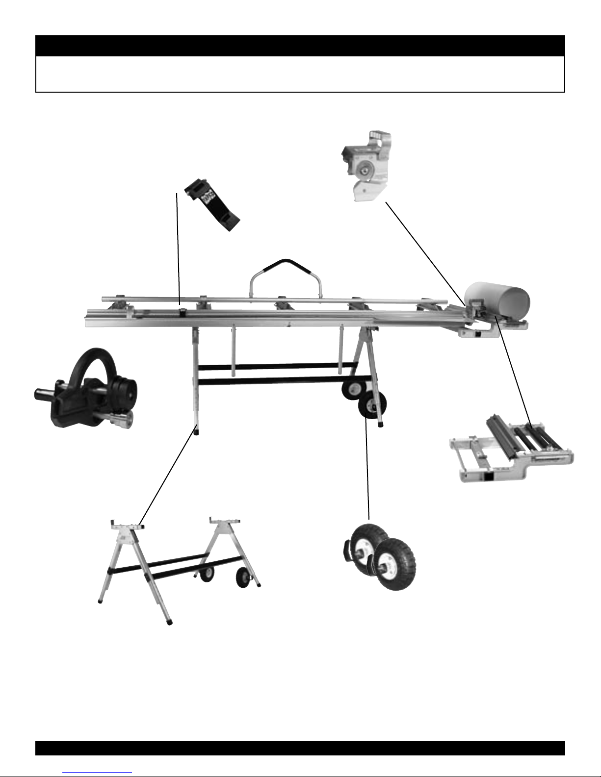
P R O 1 9 a n d P R O 1 4 B r a k e s
PRO Brake System
PRO™ Cut Off Gauge
Simplifies cutting.
PRO™ Cut-Off
Quickly, safely, and easily
makes factory quality
cuts in coil stock, sheet
metal, and vinyl siding
right on your Brake.
Brake Buddy™
Instant roll forming tool.
Snap Stand™
Heavy Duty Transportable Support;
sets up in seconds.
Side-Winder™
Works in tandem with
all PRO Series Brakes.
Wheel Kit
Allows for easy transport
of Snap Stand.
1
Page 3
Includes
molded
case.
P R O 1 9 a n d P R O 1 4 B r a k e s
PRO Accessories
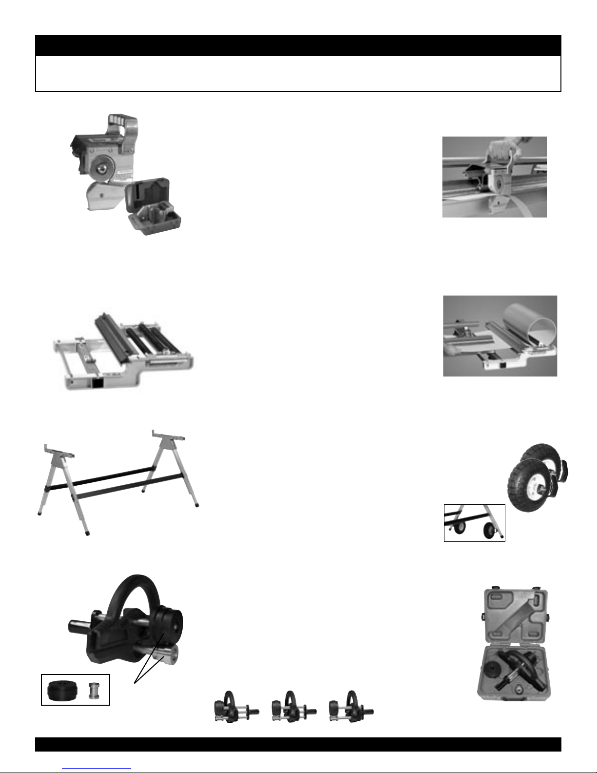
PROTM Cut-Off
Quickly, safely, and easily makes factory quality cuts in coil stock,
sheet metal, and vinyl right on your Port-O-Bender.
• Produces straight, square cuts. Reduces scrap and eliminates
knifing damage to costly bending hinges.
• Lightweight aluminum construction built to last.
• Hardened and captured tool steel cutting knives for safety and
durability.
• Eliminates use of dangerous utility knives and open blades.
• For use with all PRO Series’ Port-O-Benders (1995 and after).
• Molded carrying case protects tool when not in use.
Saves time and labor in scoring
and breaking off material.
Side-Winder
TM
Works in tandem with PRO Series Port-O-Benders to prevent coil damage.
• Allows you to feed coil directly into the jaws of your
PRO Brake. Eliminates the need for a separate layout table.
Decreases damage from handling coil stock.
• Clamping bar speeds up production, helps decrease waste.
• Attaches in seconds to the end of the PRO series Port-OBender. (modification may be needed to use unit on heavy
duty and MAX-I-MUM units)
• Holds up to 24" (61,0 cm) wide coil. Weighs only 24 lbs. (10,7 kg)
• Installs in seconds.
Snap Stand
TM
Heavy Duty Transportable Support for all PRO Series
Brakes and ProTrax™ Multi-Angle Saw Table.
• Works in conjunction with any portable siding brake.
• Variable height adjustment.
• Brake easily snaps and locks in place.
• Folds flat for easy storage.
• Durable aluminum for long life.
• Sets up in seconds.
Keeps the coil at your side
where you need it!
Optional Wheel Kit
• Allows for easy transport
of Snap Stand
• Easy to attach
• 10" Pneumatic tires
• Steel hub
Brick Mold
Rollers
Fascia Rollers
Brake Buddy
™
Instant roll forming tool for portable brakes.
• Quickly and easily forms brick mold trim and decorative ribs in .019
aluminum, PVC coated aluminum, and vinyl coated trim coil.
• Utilizes the edge of the material itself as a guide while the rib
spacing is adjustable. Two different sets of rollers included.
• Enables you to offer added style and individuality to all your jobs.
• Includes molded carrying case.
• Optional Diamond Roller.
Simply turn adjustment
handle until roller is
at desired position for
multiple ribs.
Includes molded
storage case.
2
Page 4
P R O 1 9 a n d P R O 1 4 B r a k e s
Setting Up Your PRO Brake
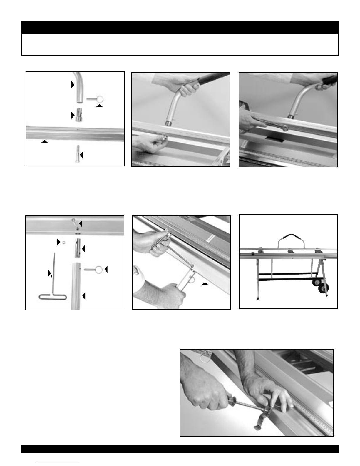
Hemming Handle Installation
Hemming
Handle
Handle
Plug
Locking Handle
The Hemming Handle Assembly includes:
(1) Hemming Han-dle, (2) Handle Plugs, (2)
Faspins, (2) Hex Bolts.
Faspin
Hex Bolt
Insert Hex Bolt through Locking Handle
of your Port-O -Bender and into base of
Hemming Handle as indicated using the
3/8” Hex Bolts provided. HAND TIGHTEN
ONLY. Repeat for other side.
Lifting/Bending Handle Installation
Moving
Hinge
Lock Nut
T-Handle
Hex Key
1
/
-20
4
1
/
-20 x 11/2"
4
Screw
Handle
Plug
Faspin
Attach the Hemming Handle over the Handle Plugs and secure them with Faspins.
Now tighten the 3/8” Hex Bolts with a 9/16”
wrench. Handle can be detached from now
on by simply removing the Faspins.
Lifting/
Bending
Handle
Remove the combination Lifting/Bending Handles from each end of the PortO - Bender by removing the Faspins as
shown.
Insert Handle Assembly into hole in bottom of Moving Hinge. Align hole in hinge
with Handle Plug and insert screw using
T-Handle Hex Key as shown. Secure with
1/4-20 Lock Nut.
Hinge Clip Installation
The Hinge Clip keeps the Moving Hinge in position for ease of
aligning material. It can also prevent rippling of the coil during
cut off operations.
To install Hinge Clip, locate predrilled hole on bottom center
of Moving Hinge. Align holes in Clip and Hinge as shown and
insert Phillips head screw provided.
Note:
You must use hinge clip when using Pro Cut-Off.
3
Secure
1
with
/
Lock Nut
-20
4
Repeat for other handle(s). To remove
handles, simply release Faspins. Always
use more than one handle when bending.
Page 5
P R O 1 9 a n d P R O 1 4 B r a k e s
Using Your PRO Brake
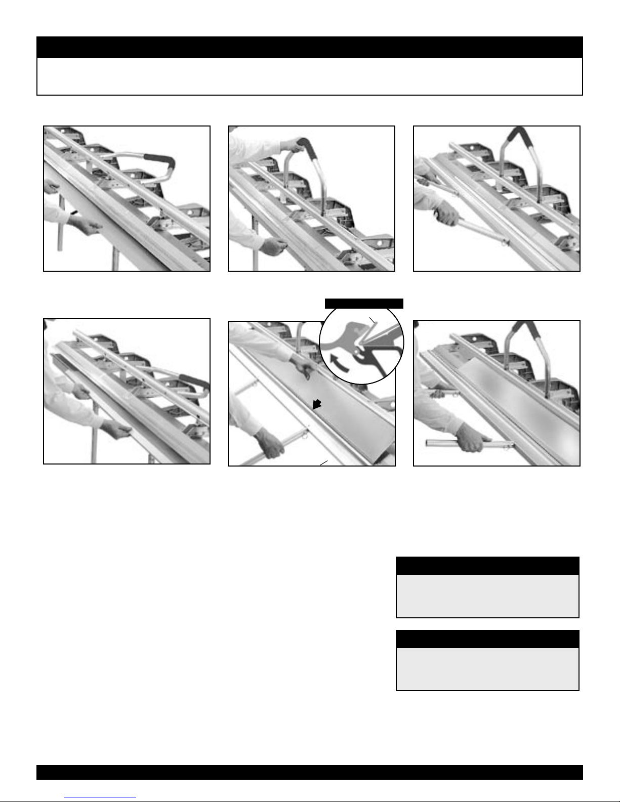
Basic Hemming and Folding
Insert the material you wish to hem into
1
your Port-O-Bender.
Remove the material from the
4
Port-O-Bender.
Care and Maintenance of your Port-O-Bender
Your Tapco Port-O-Bender® is virtually maintenance free and will provide you with
years of reliable and trouble-free performance, however, there are a few basic
necessities required to keep your Port-O-Bender® like new.
Close and lock Bender on the
2
material.
HEMMING POCKET
Material
Hemming
Pocket
Moving
Hinge
Position the bent edge of the material
5
in the Hemming Pocket on top of the
Anvil.
®
1. Clean the clamping surfaces each day before using. Use only clean shop towels
that are free of dirt, oil and metal chips.
2. Do not use your bender around your saw table as the cuttings may get in
between clamping surfaces and cause excessive wear or material scratching.
Brush away any cuttings or filings that accumulate.
Transport your Port-O-Bender® in the unlocked position. You may transport it in
3.
the locked position if you clamp a piece of cardboard or vinyl siding between the
clamping surfaces.
4. If your material is getting scratched, examine the Stainless Bending Edge, Base
Hinge and Moving Hinge for roughness or burrs. Remove burrs with emery cloth
or replace excessively worn parts. Optional Pro Cut-Off will help eliminate excessive wear to costly bending edge.
Bend as far as you can go.
3
Lift the Bending Handles and com-
6
press the bend for a completed hem.
Capacities
PRO 14/19 Bending Capacities
• Up to .030 soft aluminum
• Up to 28 ga. galvanized steel
• Up to 16 oz. copper sheet & coil
PRO 14 HD Bending Capacities
• Up to .040 soft aluminum
• Up to 26 ga.* galvanized steel
• Up to 20 oz. copper sheet & coil
MAX-I-MUM II commercial model Port-O-Benders
*
are available to bend up to 20 ga. galvanized steel.
Use a lightweight spray oil along the moving pivot hinge after every
5.
40 hours of use.
4
Page 6
P R O 1 9 a n d P R O 1 4 B r a k e s
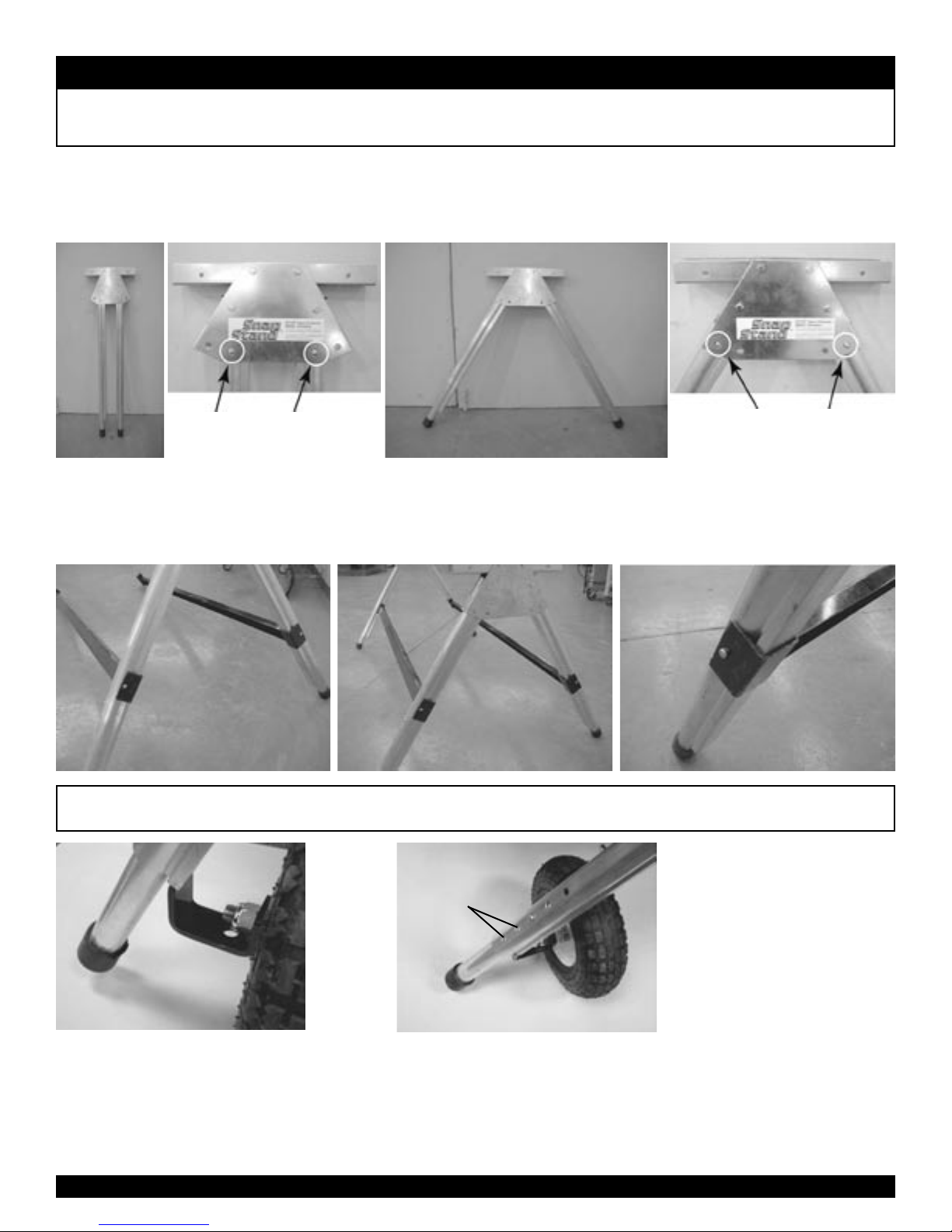
Snap Stand Set-Up
STEP 1
To open each Leg Set, push in the snap button and move each leg outward to the working
position. Figure 1A below shows the leg set as shipped while Figure 1B shows the leg set
open (working position). Make sure that the snap button pops up to lock each leg.
Snap Button locations
Figure 1A
STEP 2
Attach the Cross Braces to the Leg Sets. With the snap
button of the Leg Set pointing to the outside, snap the
Cross Braces into position. See Figures 2A and 2B below.
when legs are closed.
Figure 2A
Attaching Optional Wheel Kit
Use one of these
positions to stop the
stand from rolling.
Figure 1B
Figure 2B
Snap Button locations
when legs are open.
Note: Be sure the C-shape of the
Cross Brace is mating the leg as
shown in Figure 2C below.
Figure 2C
STEP 3
To remove the wheel assembly, tap the bracket
downward with a hammer to disengage.
STEP 1
Insert the wheel assembly into the leg of
the Snap Stand as shown in the figure
above. Tap the bracket with a hammer to
wedge it tightly into the leg. Repeat this
process for the other leg.
5
STEP 2
To prohibit the stand from rolling on the wheels, lock the leg extensions into one of the bottom two locking positions. See figure
above. If the leg extensions are in one of the other 3 positions, the
wheels are in contact with the ground and are free to roll.
Page 7
P R O 1 9 a n d P R O 1 4 B r a k e s
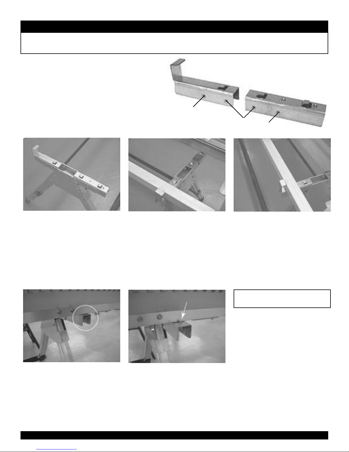
Installing Brake on Snap Stand
STEP 1
Using the 1/4-20 bolts and lock
washers provided, fasten the brake
mounts to the Leg Set. Depending
on which brake you’re using,
choose the correct holes as shown
in the figure at right.
PRO 14
snap buttons are
toward working
side of brake
Figure 2
STEP 2
The snap buttons will be towards
the working side of the brake.
Repeat Step 1 for the other Leg
Set. Be sure both ends of the Snap
Stand are going the same direction
(with the snap buttons on the same
side). See Figure 2 above.
PRO 19 & MAXI-MUM II
Back Rail clearing
adaptor hook
Figure 3A
STEP 3
Place the brake on the assembled
Snap Stand with the Back Rail of
the brake clearing the adaptor
hook as shown in Figures 3A and
3B above.
PRO 14
Figure 3B
Figure 3C
The snap button will be covered
by the fixed hinge of the brake as
in Figure 3C above.
Button pops up when brake is
fully seated
Figure 4
STEP 4
Push the brake firmly rearward
into the adaptor hooks. The snap
buttons by the front clips will pop
up and secure the brake on the
Snap Stand. See Figure 4 above.
The brake is now ready for use.
Removing the Brake:
1. Removing the brake from
the Snap Stand is essentially
the opposite of attaching it to
the stand.
2. Lifting the Moving Hinge,
depress the snap button and pull
the brake forward far enough to
hold each snap button down.
3. Be sure the box rail is out of
the Rear Clip. The brake can
now be removed from the stand.
4. Reverse Steps 2 and 1
to disassemble the stand
for transport.
6
Page 8
1
2
7
4
5
3
6
1
2
7
4
5
3
6
3
2
�
4
5
1
1
2
3
5
4
1
2
3
5
4
3
2
�
4
5
1
5
4
2
3
1
5
4
2
3
1
2
3
1
2
3
1
1
2
5
6
4
3
1
2
5
6
4
3
1
5
2
4
3
5
1
5
2
4
3
5
1
5
4
5
3
2
1
5
4
5
3
2
6
1
4
2
5
3
6
1
4
2
5
3
2
1
2
1
P R O 1 9 a n d P R O 1 4 B r a k e s
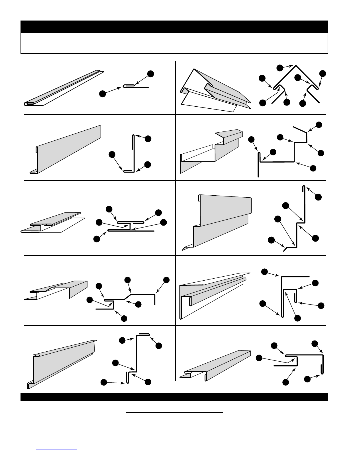
NOTE: UP & DOWN refers to the clad,
Common Shapes
painted or FINISH SIDE of the material as
it is placed into the Bender.
1. All Purpose Sill Trim
Down
2. Fascia Trim
Down
Down
7. Counter Flashing
Down
Down
3. One Piece Soffit Mitre 8. Brick Frieze
Down
Up
Down
Up
Down
Up
Down
Up
Down
Down
Down
Up
Up
Down
Up
Up
Down
Down
Down
Down
Up
4. Rake Trim with “J” Channel
Down
Up
5. Soffit or Frieze Trim
Down
Down
©2004 Tapco International Corporation
9. “F” Channel/Inside Corner
Down
Up
Up
Down
Up
10. Window or Door Casing
with “J” Channel
Down
Up
TAPCO PRODUCTS COMPANY
29797 Beck Road • Wixom, MI 48393-2834
A Division of Tapco International
www.tapcoint.com
Up
Up
Up
Up
Down
Up
Up
Down
Down
Down
Down
Down
Item # 13043
T3227-LS 4/04
Page 9
(not shown)
(not shown)
Hemming Handle Plugs (2)
3/8–16 x2 1/4" Bolt (2)
3/8–16 x2 1/4" Bolt (2)
10 pins, 20 keepers
10 pins, 20 keepers
(plugs, nuts, & bolts) 2 ea.
(plugs, nuts, & bolts) 2 ea.
1/4–20 x 2 1/2" Bolt (5)
1/4–20 Nulok Nut (5)
1/4–20 Nulok Nut (5)
3 Roller Spring
Pan HD Screw
Coupling Nut Kit (2)
1/4–20 x 3/4" Screw (2)
1/4–20 x 3/4" Screw (2)
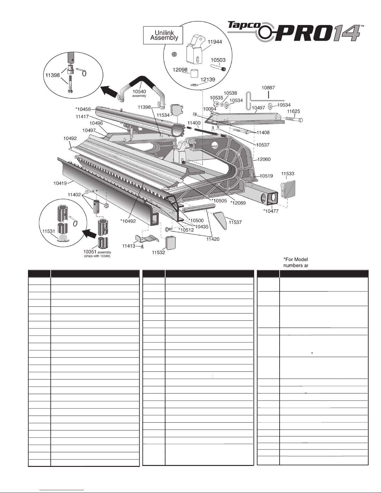
Item # Description
3/8–16 x2 1/4" Bolt (2)
3/8–16 x2 1/4" Bolt (2)
Item # Description
Item # Description
 Loading...