

Page 1
PV WEB DATA LOGGER
TK-E20-01/08/16/08S/16S/32D Instruction
1. General
TAOKE web data logger of PV plants collects the operation data,
including inverter, radiation, meter data, etc. by RS-485/422, and
sends these data to website via ethernet so that user can check
the power station running status by logging on to internet website.
2.Scope of supply
This logger will be delivered with the following components:
1. TK-E20 PV web data logger
2. Power adapter 220VAC input ,12V DC /1A output
3. Manual
4. CD disk
5. Wall plug and screw
3. Technical data
Product parameters Tech-Specifications
Power supply 220V AC /12V DC
Static power consumption
Active power consumption
Indication for status 4(top)+2(rear) LEDs
Internet Connection Ethernet
Ethernet connection 10BASE-T/100BASE-TX
Ethernet interface RJ45-CAT5
PV device(inverter etc.) connection RS485/422
RS485/422 baudrate
RS485/422 cable length Maxim 1000m
RS485/422 interface RJ45
Data collection interval 5~30min(optional)
Operation temperature
Protection type IP21(In-door use only)
Installation Desktop or Wall-mounting
L ×W ×H 135×85×25mm
Configration Via computer
<2W
<5W
1200~38.4K bps
-10~55℃(14~131℉)
4.Ordering information
TK-E20-×××
Sending data via ethernet to intranet server added
Max. number PV devices(inverters,meters,etc.)
Sending data via ethernet to internet server
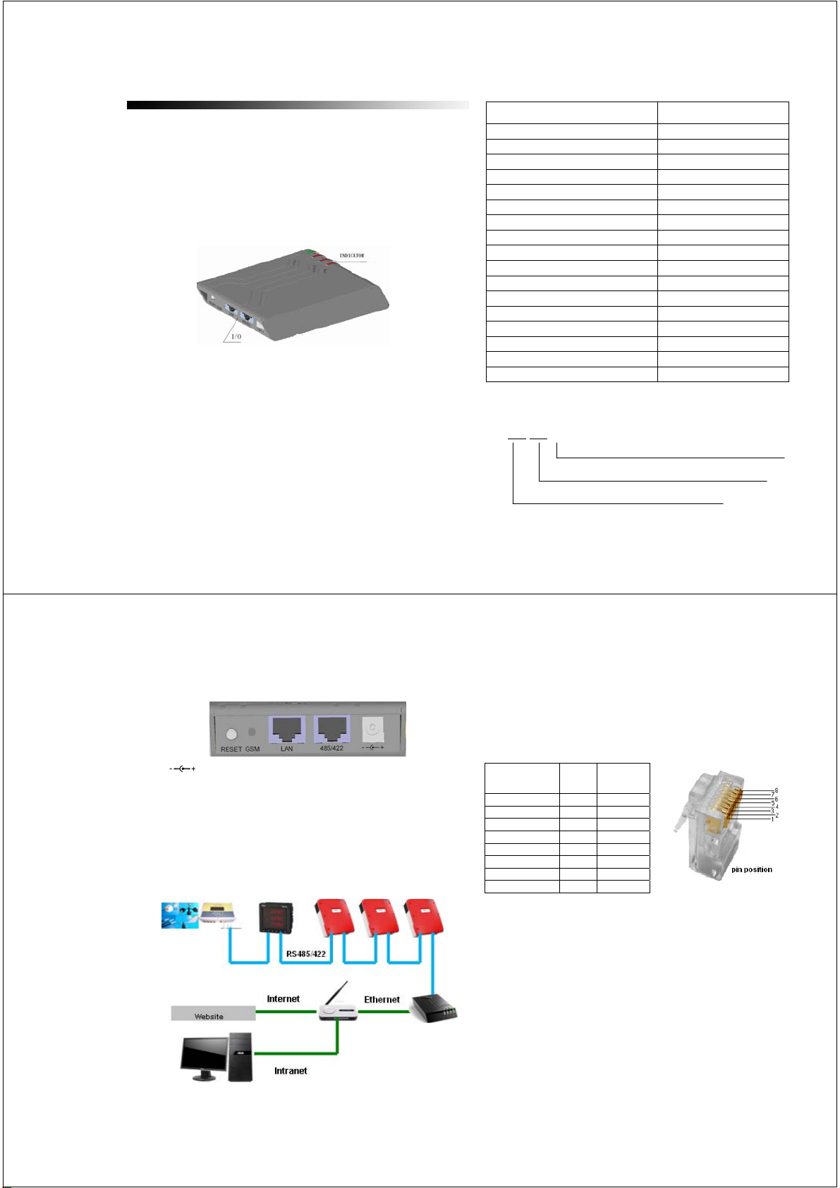
5.I/O illustration
: DC power socket
485/422: RS-485/422 socket
LAN: Ethernet socket
GSM: No
RESET:Key for reset to “IP address allocated via DHCP
automatically”
6. Installation
Field connection diagram
1 2
PV web data logger should be installed where dry and ventilation
are required in-door. It can be installed by desktop or
wall-mounting.
Connection the logger via “RS485/422” socket to the PV devices,
including inverter, meter, sensor (radiation, temperature etc.) etc.,
and wiring among each other with CAT5 cable.
RJ45 Pinouts/
Color of wire
1 NC NC
2 NC NC
3/white green R+
4/Blue T+ 485+(A)
5/White blue T- 485-(B)
6/Green R-
7/ Brown GND GND
8 GND GND
RS-422/485 foot pin and CAT5 wire correspondence of logger
The logger is set to identify network via DHCP automatically.
Connection the logger via “LAN” socket to a network router with
network cable, the LED-ETHERNET flashes quickly. When the
LED is steady on, the IP address is allocated. If the LED flashes
slowly after one minute, the IP address is not allocated
automatically. You can set a fix IP address via computer. Read the
“Logger set tool User Manual” and use the “Logger set tool.exe” in
the disk.
If you want to reset “IP address allocated via DHCP
automatically”, pull out the DC plug, press the reset key and
plug in at the same time. The 4 LEDs on top are flashing. When all
the LEDs are steady on, release the key.
NOTE:Each logger connected to a network has got its own IP
3 4
RS422 RS485
Page 2
address. This address can not be used twice and can not be
allocated to another logger, computer, etc. appliance. When the
‘ETHERNET’ indicator is steady on, but there is no data on website
or you can not search the logger via computer with “Logger set
tool.exe”. If the logger is set a fix IP address, you have set a
wrong IP address or the IP address is allocated twice. If the logger
is allocated IP address via DHCP automatically, the IP address is
allocated twice.
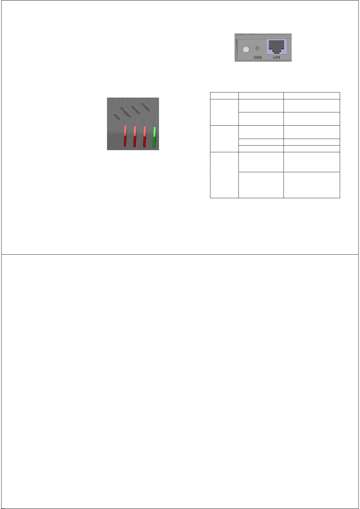
7.Led illustration
POWER:steady on when power supply is normal.
485/422:Off,no data is collected.
flash 150ms when collection.
Steady on,when all the data is collected correctly.
500ms On/500ms Off, some data can not be collected.
ETHERNET:Off,cable not connected to a router or a computer.
Steady on,the IP address is allocated.
500ms On/500ms Off, obtaining IP address automatically.
500ms On/2500ms Off, IP address can not be allocated.
GPRS:Off.
5 6
LAN: The two LEDs Off, ethernet is no linked.
The two LEDs blinking,ethernet is linked.
8. Trouble shooting
Symptom Analysis Handling
indicator off
‘RS485/422’
indicator off
or flash
‘ETHERNET’
indicator off
or flash
DC power not connects
in or get loose.
Power adaptor
malfunction
Wiring not connects or
get loose
PV device malfunction
Parameters’ wrong
Network disconnecting
when the indicator is off
The IP address is
something wrong when
the indicator flash
Reconnecting power after
checking the circuit.
Replace power adaptor.
Check cable among the logger
and PV devices.
Check PV device.
Contact installing personnel.
Check the “LAN” socket, if the
two LEDs are not blinking,
check if the cable get loose.
If the LEDs of “LAN” socket
are blinking, the IP address is
set wrong, or this address is
allocated twice.
‘Power’
NOTE
This equipment has been tested and found to comply with the
limits for a Class B digital device, pursuant to part 15 of the FCC
Rules. These limits are designed to provide reasonable protection
against harmful interference in a residential installation.
This equipment generates, uses and can radiate radio frequency
energy and, if not installed and used in accordance with the
instructions, may cause harmful interference to radio
communications. However, there is no guarantee that interference
will not occur in a particular installation.
If this equipment does cause harmful interference to radio or
television reception, which can be determined by turning the
equipment off and on, the user is encouraged to try to correct the
interference by one or more of the following measures:
—Reorient or relocate the receiving antenna.
—Increase the separation between the equipment and receiver.
—Connect the equipment into an outlet on a circuit different from
that to which the receiver is connected.
—Consult the dealer or an experienced radio/TV technician for
help.
7 8
 Loading...