

Page 1

STS.01
Spartan Iridium Transceiver
Antenna System
User Manual
Page 1 of 14
Page 2

Contents
1. Introduction .................................................................................................................................. 3
2. Installation .................................................................................................................................... 3
3. Cable ............................................................................................................................................... 5
4. Powering the Device .................................................................................................................. 6
5. Enabling the Iridium Radio ..................................................................................................... 6
6. Serial Communication............................................................................................................... 6
7. Network Available Output ....................................................................................................... 6
8. Tamper Detection ....................................................................................................................... 7
9. Device Performance .................................................................................................................. 8
10. Mechanical Drawing ................................................................................................................. 14
Page 2 of 14
Page 3

1. Introduction
This document covers details and usage of the Spartan STS.01 product. The
document includes installation and functional instructions for the user.
2. Installation
The device needs to be installed so that it has a clear view of the sky. The flat, metal
base plate should be facing downward, and the domed plastic top is required to be
pointed straight up at the sky. Iridium is a satellite system so the unit needs to be
able to see the satellites in order to communicate with the Iridium system.
The provided washer and nut can be used to mount the device through a hole in a
flat surface, as shown below in Figure 1. The bottom of the device has an adhesive
foam pad that keeps the unit from rotating in place. This also seals the hole from
water ingress. Be sure to remove the paper backing prior to seating the unit in its
mounting hole.
Page 3 of 14
Page 4

Figure 1 - Proper Device Orientation
Page 4 of 14
Page 5

Conductor Color
Conductor Function
Red
Power Input (+8-32V)
Black
Power and Signal GND
Orange
On/Off Control (>1.4v Input to enable Iridium module)
Blue
Network Available (+3.3V Output)
Green
RX (Relative to Antenna Module)
Yellow
TX (Relative to Antenna Module)
Gray
Tamper Detect
White
Chassis Ground
Drain Wire
Internally connected to Chassis Ground
3. Cable
The STS.01 has a single 8-conductor cable for power and communication. The
conductor description is as follows:
Figure 2 – Cable Diagram
Page 5 of 14
Page 6

4. Powering the Device
The power input (red conductor) can be supplied with +8 to +32V. The black
conductor is the signal and power ground for the device. The power/signal ground
must be connected to the same GND as the power source. This same connection is
also the ground reference for the serial interface and must be broken out (split) for
both power input and signal ground functions.
Chassis ground (white conductor and drain wire) can be tied to power/signal ground
or can remain isolated. Chassis ground is not electrically connected to anything inside
the product, other than the metal base plate and the tamper detection line.
5. Enabling the Iridium Radio
Once the device is powered it is in idle state. There will be no radio communication
until the user enables the Iridium module. A voltage of at least 1.4V must be applied
to the orange conductor to enable the radio. This line may be connected to the power
input of the device if desired.
6. Serial Communication
Once the device is powered and the radio is enabled, communication with the radio
module can occur via RS232C signaling levels. The default baud rate of the device
is 19200-N-8-1. The green conductor is the device RX (input) and the yellow
conductor is the device TX (output). The Iridium AT command set must be used for
configuration and communication.
7. Network Available Output
The Network Available digital output (blue conductor) can be monitored to verify
network availability. This output will be +3.3V when the radio can see a satellite and
0V when no network is available. This signal is current limited with an internal 10k
resistor.
Page 6 of 14
Page 7
8. Tamper Detection
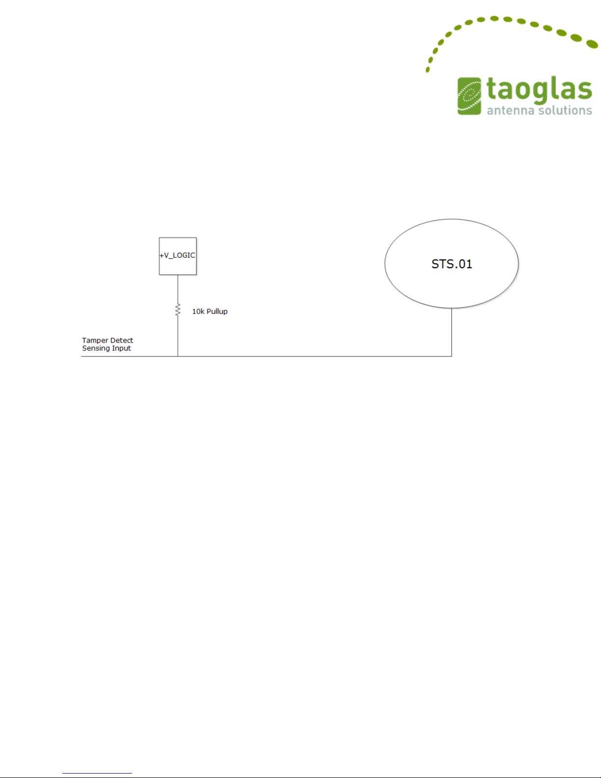
The tamper detection conductor can be used to determine if the cable has been
accidentally or intentionally cut by implementing a 10k ohm pullup resistor on the
user’s OEM device that the STS.01 connects to, as shown below in Figure 3.
Figure 3 - Tamper Detection Pullup
Vlogic is the logic high supply voltage of the sensing input device. While the device's
cable is intact, the tamper detection line will be 0V. When the cable is cut, Vlogic will
be present on the tamper detection line.
The tamper detection line is connected to the Chassis Ground line of the cable and
thus to the base of the device. This signaling scheme assumes the Chassis Ground
line is connected to the same reference ground as the ground reference of the sensing
device.
Using the tamper detection line is optional. The device is fully functional if the user
decides not to use the tamper detection line. If unused tamper detect should be left
floating or tied to the same point as Chassis Ground.
Page 7 of 14
Page 8
180 Second
I2P Voice
Calls
Call
Attempts
Call
Setup
Rate
Call
Drop
Rate
Average
Channel
Assignment
Time
Access
Rate
Average
Access
Time
Average
Setup
time
Spartan
STS.01
Transceiver
Antenna
System
1220
98.03%
2.93%
4.97
98.20%
7.17
9.85
Iridium
Transceiver
+ Baseline
Antenna
1220
98.77%
1.99%
4.76
99.02%
6.93
9.6
9. Device Performance
9.1 Iridium Approval
The Spartan STS.01 has been approved by Iridium for use on the Iridium satellite
system. The approval process involves a side-by-side comparison to Iridium's
baseline antenna. The baseline antenna is similar in size to the Spartan STS.01.
Therefore, the baseline antenna should be viewed as maximum potential
performance for any device. There are 4 performance characteristics that are covered
in this comparison. Those characteristics are Voice Mode Call Performance, Data
Mode Performance, Downlink Margin, and Power Control Efficiency. The testing
results are shown in the following sections.
9.1.1 Voice Mode Call Performance
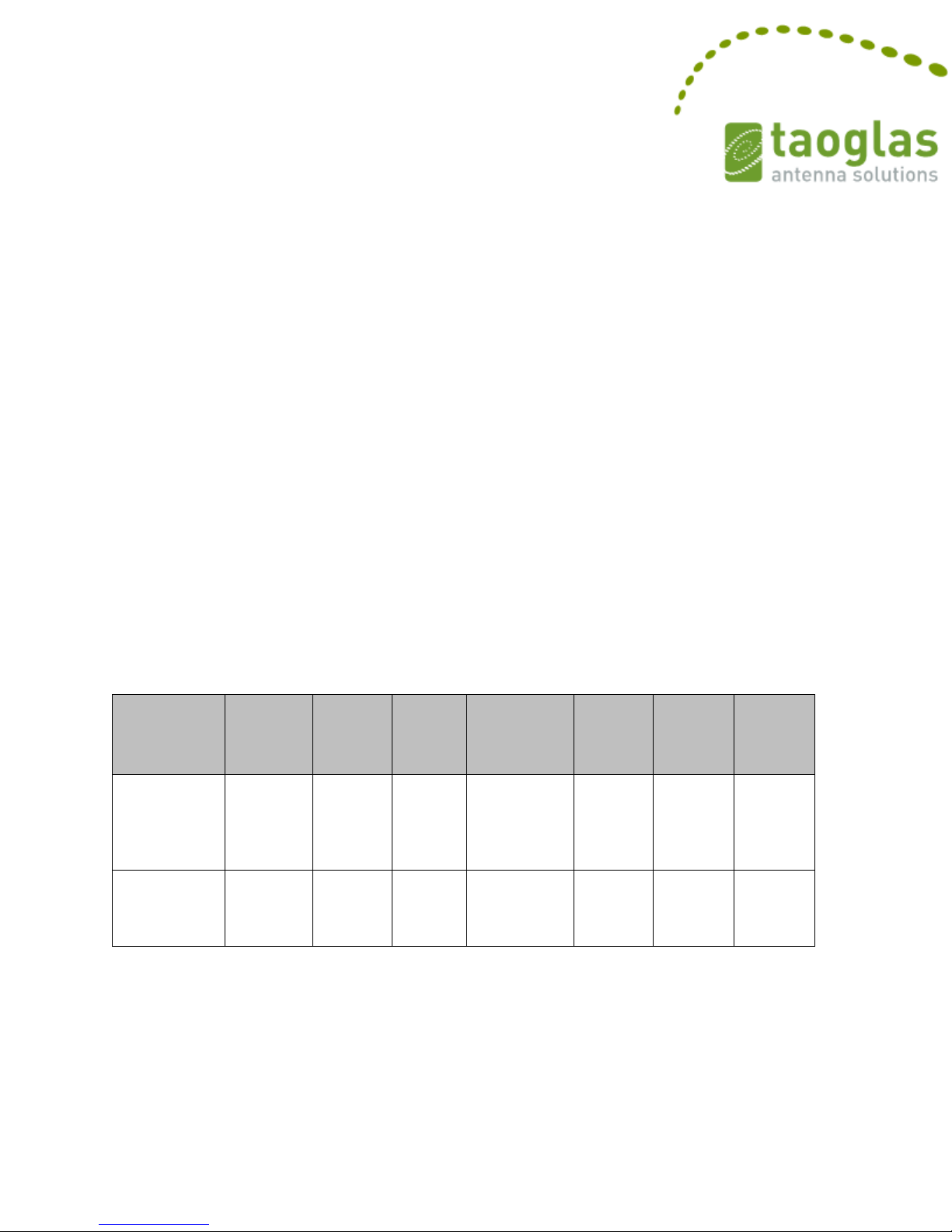
The test consisted of 180 second calls being made to the gateway used in testing.
Figure 4 contains the performance results for the antenna for the test duration.
Figure 4 - Voice Mode Call Performance
Page 8 of 14
Page 9
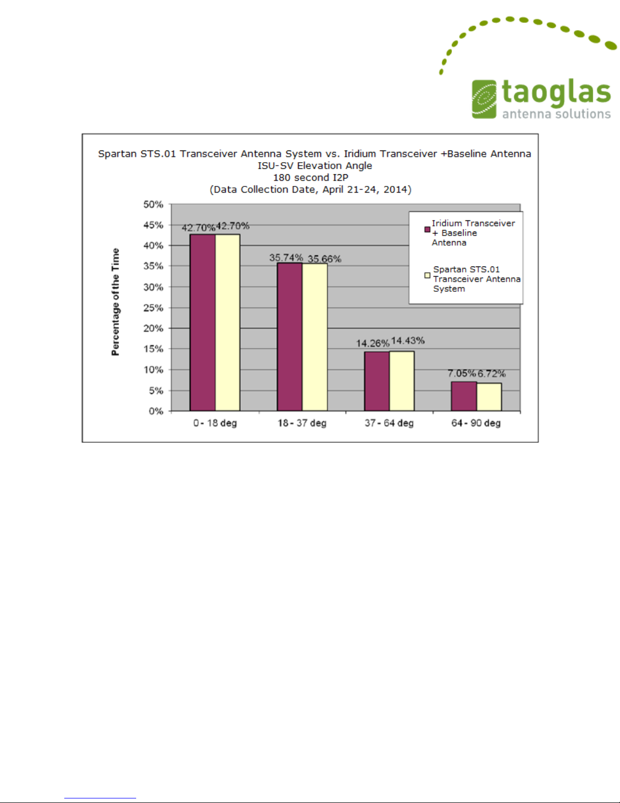
Figure 5 - Voice Mode Call Performance
Page 9 of 14
Page 10
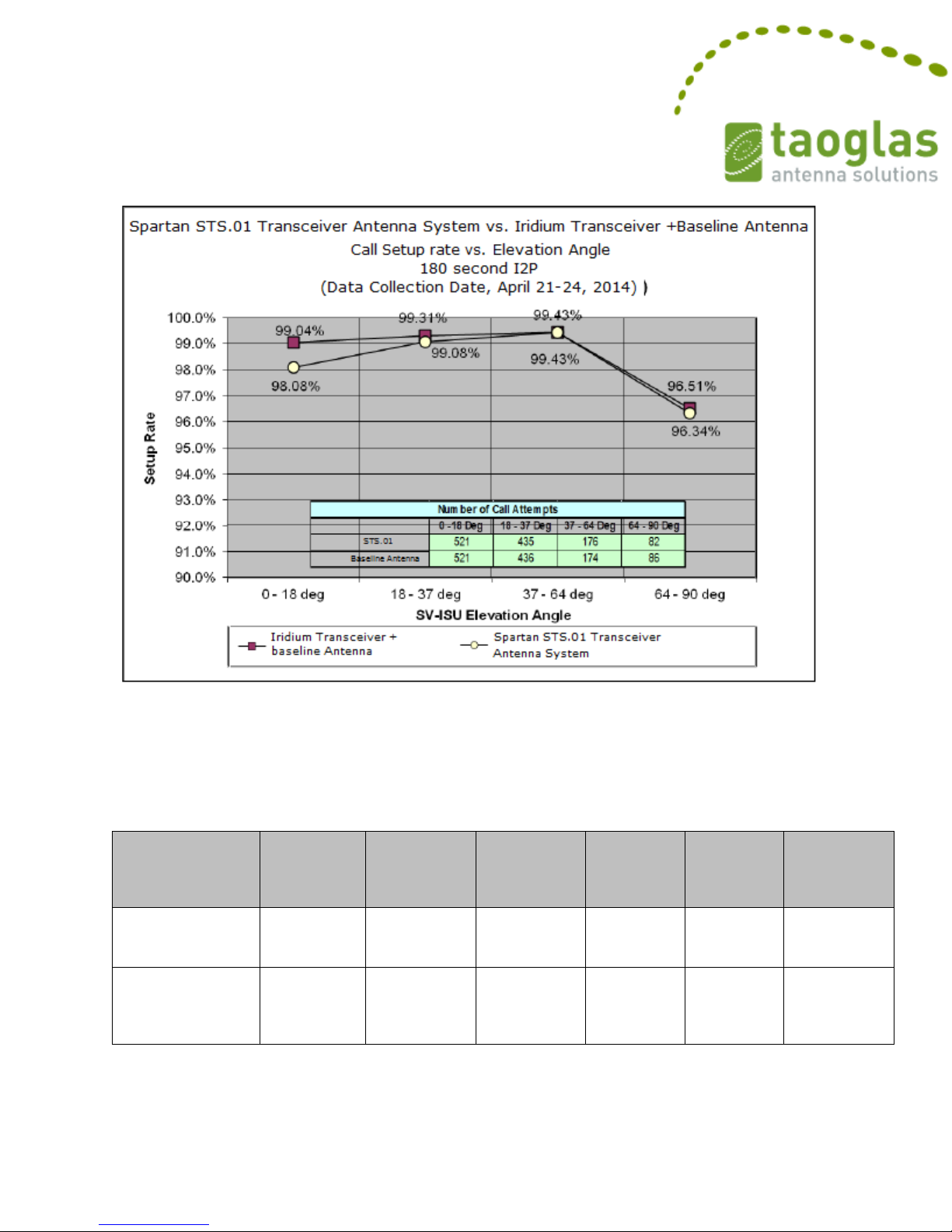
Figure 6 - Call Setup Rate vs. Elevation Angle
FTP 50K Upload
Call
Attempts
Call
Connect
Count
Successful
Call
Connect
Rate
Successful
Transfer
Count
Successful
Transfer
Rate
Average
Throughput
(Kb/sec)
Spartan STS.01
Transceiver
Antenna System
942
891
94.59%
856
90.87%
2.62
Iridium
Transceiver +
Baseline
Antenna
946
909
96.09%
891
94.19%
2.66
9.1.2 Data Mode Performance
Data was collected for one day from data calls performing 50k FTP upload transfers.
Figure 7 - Data Mode Performance
Page 10 of 14
Page 11
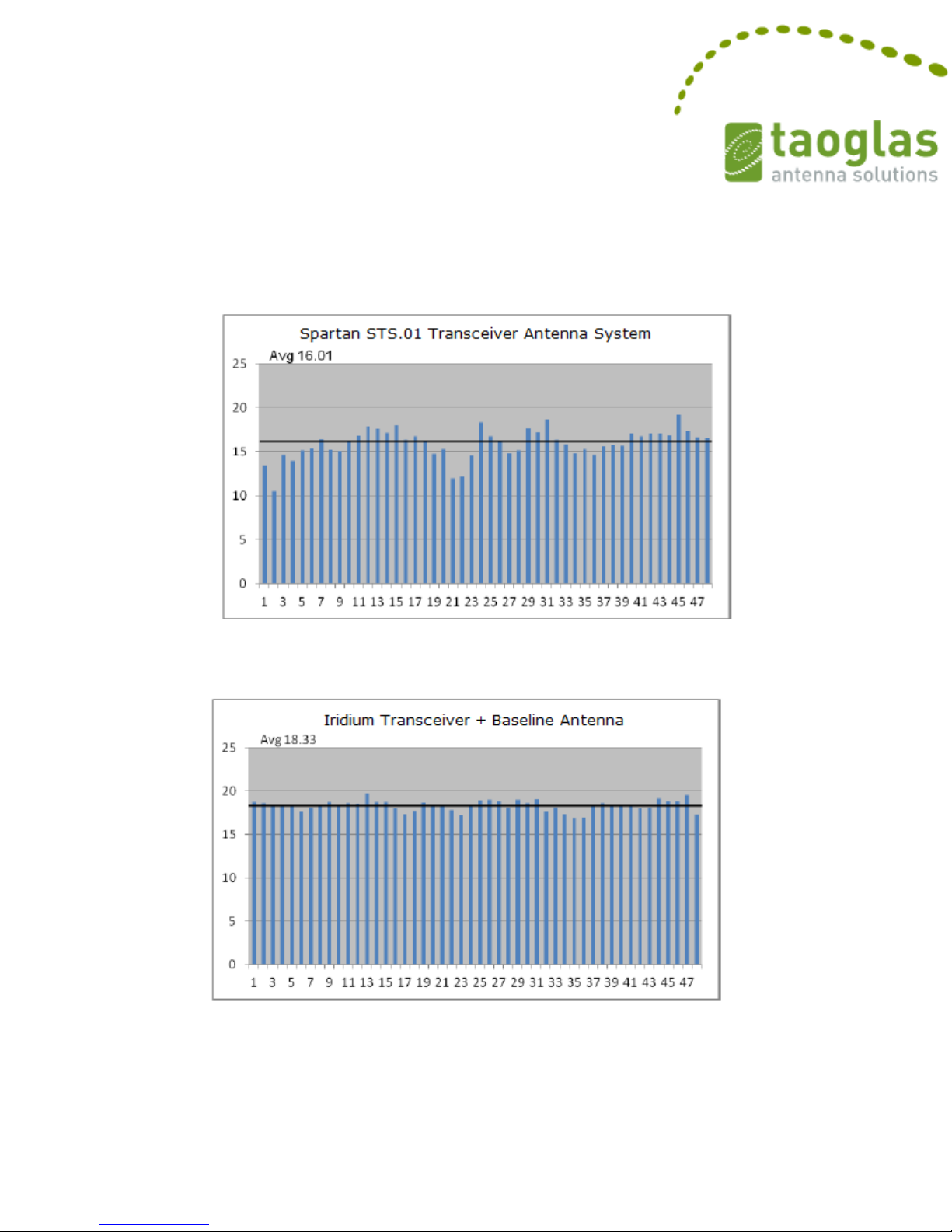
9.1.3 Downlink Margin Performance
The figures below depict the link margin on a per beam basis, evaluating only the
traffic channel and does not include values that are 0 dB or less.
Figure 8 – Spartan STS.01 Transceiver Antenna System Link Margin per Beam
Figure 9 – Iridium Transceiver + Baseline Antenna Link Margin per Beam
Page 11 of 14
Page 12
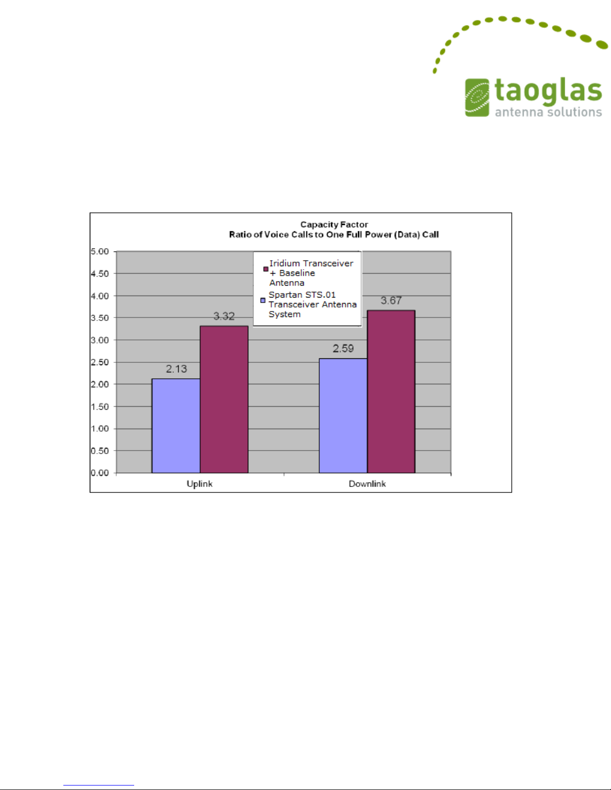
9.1.4 Power Control Efficiency
The results are presented in terms of Capacity Factor, which is a ratio of voice call
power to full power. Capacity Factor is calculated by determining the amount of time
spent at various power levels during uplink and downlink.
Figure 10 - Capacity Factor
9.2 Automotive Electrical Transients
The STS.01 is designed to maintain at least Class C operation for all transients defined
in ISO 16750-2, ISO 7637-2, and ISO 7637-3. Class C operation means the device
functionality will return to normal after the transient event without user intervention.
The STS.01 actually maintains Class A operation for many of the transients including
the load dump transient, defined in ISO 16750-2, Section 4.6.4, complying with the
most severe 24V system requirements. Class A operation means the device functions
as designed without interruption and without user intervention during the transient
event. Other similar devices incorporate a user-replaceable fuse to overcome the
severe load dump transient. This allows the manufacturer to claim Class D operation,
meaning the user has to remove the device from its mounting location, open it up,
Page 12 of 14
Page 13

and replace the fuse to get the device back to normal operation after a transient
event. This is not convenient in many applications, which is why the STS.01 is a
superior option.
A short-circuit test is also defined in ISO 16750-2, Section 4.10, where all inputs and
outputs must be tied to the power source and then to ground for a duration of 60
seconds each. This verifies there is no damage to the device when the user
accidentally connects an I/O line to the wrong terminal. The STS.01 completed all of
these tests assuming a 24V system, resulting in a very robust device.
Refer to ISO 16750-2, ISO 7637-2, and ISO 7637-3 for a complete list of
specifications. The STS.01 successfully meets all of the requirements defined.
Page 13 of 14
Page 14
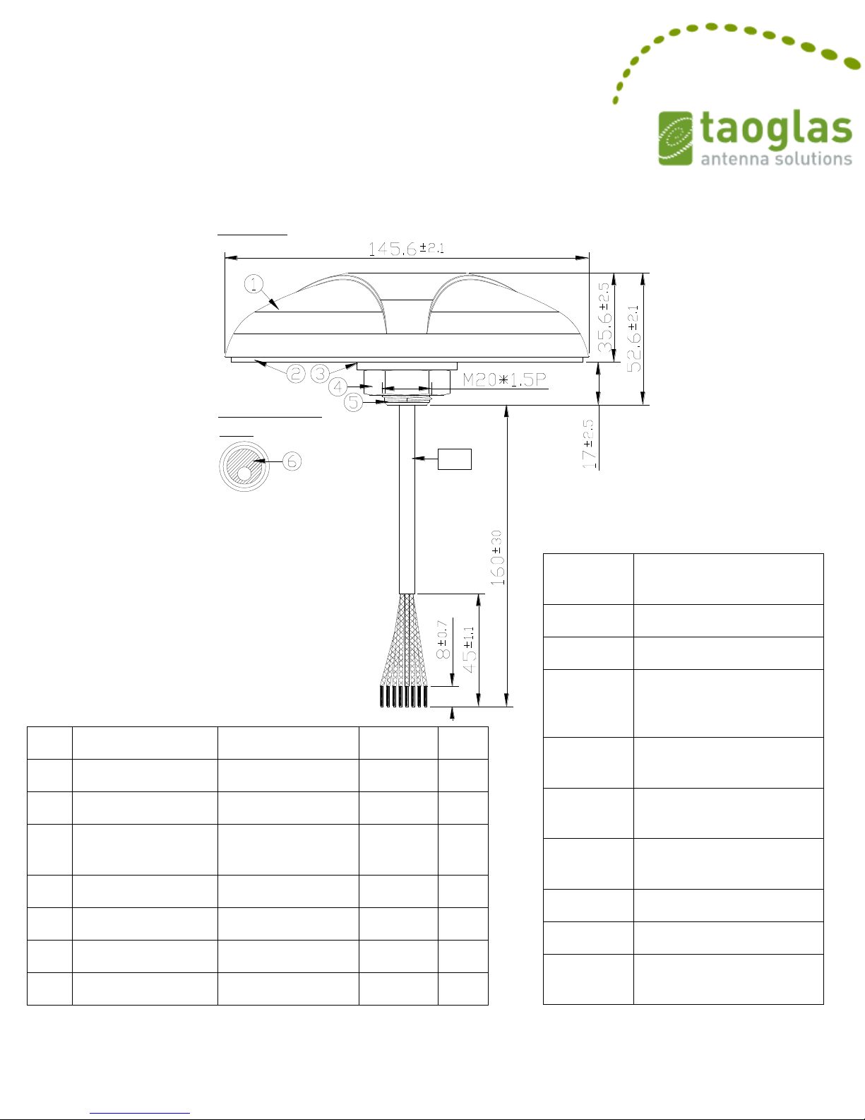
10. Mechanical Drawing
Side View
Bottom Thread
View
UU
Name
Material
Finish
QTY
1
Housing Spartan ST
PC + ABS
Black 1 2
Closed Cell Foam
3M 9448+CR-4305
Black
1
3
Nut_M20x1.5Px10H
Cut
Steel
Ni Plated
1
4
Washer Nut
Steel
Ni Plated
1
5
Metal Base ST
Zinc Alloy
Ni Plated
1 6 Cable Rubber
Silicone Rubber
Black
1
UU
Cable Type
5118C
Grey
1
See table for
Conductor
detail
Conductor
Color
Conductor Function
Red
Power Input (+8-32V)
Black
Power and Signal GND
Orange
On/Off Control (>1.4v
Input to enable Iridium
module)
Blue
Network Available (+3.3V
Output)
Green
RX (Relative to Antenna
Module)
Yellow
TX (Relative to Antenna
Module)
Gray
Tamper Detect
White
Chassis Ground
Drain Wire
Internally connected to
Chassis Ground
Page 14 of 14
 Loading...