

Page 1
VX Series
Professional Loudspeakers
Operation Manual
Page 2

Important Safety Instructions
2
VX Series Operation Manual rev 1.1.2
SAFETY WARNING
Do not remove any covers, loosen any xings or allow
items to enter any aperture.
SAFETY WARNING
Objects lled with liquids should not be placed on
this apparatus.
AVERTISSEMENT DE SECURITE
Ne retirez pas les couvercles, ne desserrez pas les xations et
ne laissez aucune pièce s’introduire dans les ouvertures.
AVERTISSEMENT DE SECURITE
Ne placez pas d’objets contenant du liquide à proximité de
l’appareil
.
Important Safety Instructions
1. Read these instructions.
2. Keep these instructions
3. Heed all warnings.
4. Follow all instructions.
5. Do not use this apparatus near water.
6. Clean only with a dry cloth.
7. Do not block any ventilation openings. Install in accordance
with the manufacturer’s instructions.
8. Do not install near any heat sources such as radiators, heat
registers, stoves, or other apparatus (including ampliers that
produce heat.
9. Only use attachments/accessories specied by the manufacturer.
10. Use only with a cart, stand, tripod, bracket, or table
specied by the manufacturer, or sold with the apparatus.
When a cart is used, use caution when moving the cart/apparatus
combination to avoid injury from tip-over.
11. Refer all servicing to qualied service personnel. Servicing
is required when the apparatus has been damaged in any
way, such as power-supply cord or plug is damaged, liquid
has been spilled or objects have fallen into the apparatus, the
apparatus has been exposed to rain or moisture, does not
operate normally, or has been dropped.
The lightning ash with arrowhead symbol within an
equilateral triangle, is intended to alert the user to the
presence of uninsulated "dangerous voltage " within the
product's enclosure that may be of sucient magnitude
to constitute a risk of electric shock to persons.
The lightning ash with arrowhead symbol within an
equilateral triangle, is intended to alert the user to the
presence of uninsulated "dangerous voltage " within the
product's enclosure that may be of sucient magnitude
to constitute a risk of electric shock to persons.
The exclamation point within an equilateral triangle is
intended to alert the user to the presence of important
operating and maintenance (servicing) instructions in the
literature accompanying the product.
Page 3

Table of Contents
VX Series Operation Manual rev 1.1.2
3
Table of Contents
2. Introduction............................................................................................................................................... 4
3. Unpacking and Visual Checks ................................................................................................................ 4
3.1 Preliminary Recommendation ................................................................................................................9
4. Connectors / Cabling ...............................................................................................................................5
5. Polarity Checking ..................................................................................................................................... 6
6. Amplication and Power Handling ......................................................................................................... 6
7. Crossover and Bi-amp Conguration .................................................................................................... 7
8. Equalisation ..............................................................................................................................................9
9. Arraying ................................................................................................................................................... 10
10. Dimensions ............................................................................................................................................. 11
11. Rigging and Safety Procedures ............................................................................................................ 16
12. Service Parts and Accessories ............................................................................................................. 17
13. Technical Specications .......................................................................................................................18
14. Warranty ..................................................................................................................................................22
15. Declaration of Conformity ..................................................................................................................... 23
Page 4

2. Introduction
4
VX Series Operation Manual rev 1.1.2
2. Introduction
Designed, engineered and built in the United Kingdom, the VX Series from Tannoy comprises a range of
passive loudspeakers for demanding professional and commercial sound applications. At the heart of all VX
Series loudspeakers is Tannoy’s acclaimed Dual ConcentricTM driver technology. Unlike conventional drivers,
Dual Concentric combines a high frequency driver and a low-mid driver on a common axis, creating a true
point source for all reproduced sounds. Dual Concentric eliminates the time alignment problems inherent with
all enclosures employing separated drivers, thus ensuring outstanding denition, detail and intelligibility at all
points in the listening area.
All VX Series loudspeakers are designed to perform with very high efciency and exceptionally low distortion,
even when operating near peak output levels. All components are housed in rugged birch plywood enclosures,
with larger models equipped with double-chamfered Integrip™ recessed handles for easy one- or two-handed
carrying. Reecting Tannoy’s reputation for reliability, all VX Series loudspeakers are backed by a ve-year warranty.
Within the VX Series, system designers can choose from a variety of sizes, power levels and coverage patterns
to suit particular requirements. For extended bass performance, models with the “.2” designation augment the
Dual Concentric LF driver with a second matched LF driver. The “HP” designation indicates extended power
handling capabilities, while the “Q” sufx indicates incorporation on the new Q-Centric WaveguideTM (QCW™)
for applications requiring an asymmetrical coverage pattern. The QCW horn can be rotated in a matter of
minutes, allowing placement of the 75 x 40 degree pattern with either horizontal or vertical orientation.
3. Unpacking and Visual Checks
Each Tannoy VX Series loudspeaker is carefully tested and inspected prior to shipment. After unpacking,
please inspect for any exterior physical damage, and save the carton and any relevant packaging materials in
case the loudspeaker again requires packing and shipping. In the event that damage has been sustained in
transit notify your dealer and the shipping carrier immediately.
3.1 Preliminary Recommendation
VX Series loudspeakers can produce high sustained output levels for long periods of time. If users are in close
proximity, these levels could lead to permanent hearing damage. Because Tannoy loudspeakers have a naturalsounding, at frequency response and very low distortion, users may not be aware of the potential hazard. For
continuous exposure to high levels, we recommend use of a sound level meter to ensure noise levels are within
safety limits. The meter should be capable of integrating levels over a period of exposure in conformance with
noise control standards.
Page 5

4. Connectors / Cabling
VX Series Operation Manual rev 1.1.2
5
4. Connectors / Cabling
On VX Series loudspeakers, connector types available vary by model, as detailed below:
VX 5.2, VX 6, VX 8
Inputs on 1 x speakON® 4-pole, 1x binding post pair. Binding posts are connected in parallel to speakON® 1+
and 1-. Not bi-amp capable.
VX 8.2, VX 12
Inputs on 2 x speakON® 4-pole and 2 x barrier strip terminals. Both barrier strip terminal pairs are connected in
parallel to speakON® poles 1+ and 1-. Not bi-amp capable.
VX 12HP, VX 12Q, VX 12.2Q, VX 15HP, VX 15Q
Inputs on 2 x speakON® 4-pole and 2x barrier strip terminal pair. Both barrier strip terminal pairs are connected
in parallel to speakON® poles 1+ and 1- when congured for full range operation. Bi-amp conguration may be
implemented using speakON® connectors only. (See 6.0 below.)
Binding post terminals are capable of accepting cables with a conductor of up to 6 mm sq CSA (AWG 10). Red
is positive and black is negative.
Barrier strips accept wire up to 4 mm sq CSA (AWG 12). Barrier strip polarity is as indicated.
The speakON® connectors will accept wire up to 4 mm sq CSA (AWG 12) with an outside diameter of up to 15
mm and a current rating of 30 A. When so equipped, the pins of the two speakON® sockets identied input/
output on the rear of the input panel are paralleled within the enclosure. Tannoy have adopted the conventional
wiring standard for the VX Series product: pin 1+ is positive pin 1- is negative. For a worldwide list of Neutrik®
distributors see www.neutrik.com.
When choosing cable type, it is important select the correct cross sectional area in relation to the cable length
and the load impedance. A small cross sectional area will increase the cable’s series resistance, inducing power
loss and response variations (damping factor). Connectors wired with 2.5 sq. mm (12 gauge) cable will be
satisfactory under normal conditions; with very long cable runs, the wire size should be increased. Please refer
to the following table for guidance:
Cable run (m)
C.S.A of Each
Conductor
Cable resistance
(ohms)
% Power loss
into 8 ohms
load
% Power loss
into 4 ohms
load
10
2.5
4.0
6.0
0.14
0.09
0.06
1.7
1.1
0.73
3.5
2.2
1.5
25
2.5
4.0
6.0
0.14
0.09
0.06
1.7
1.1
0.73
3.5
2.2
1.5
50
2.5
4.0
6.0
0.14
0.09
0.06
1.7
1.1
0.73
3.5
2.2
1.5
100
2.5
4.0
6.0
0.14
0.09
0.06
1.7
1.1
0.73
3.5
2.2
1.5
Page 6

5. Polarity Checking
6
VX Series Operation Manual rev 1.1.2
5. Polarity Checking
Checking the polarity of the wiring before the speaker system is mounted or own will help ensure satisfactory
performance. If you do not have a pulse based polarity checker, you may check LF units as follows: Connect
two wires to the + and - terminals of a PP3 (9 V) battery. Apply the wire connected to the positive (+) terminal
of the battery to the speaker cable leg which you believe to be connected to pin 1+ of the speaker connector;
likewise connect the negative (-) terminal of the battery to pin 1-. If you have wired it correctly, the LF drive unit
will move forward. At this point, connect the positive (+) speaker lead to the + terminal on the amplier and the
negative (-) lead to the - terminal on the amplier. However, if the LF driver moves backwards with the battery
test, the input connections need to be inverted before connecting the amplier. If problems are encountered,
inspect the cable wiring. Note that different amplier manufacturers may utilise different pin congurations and
polarity conventions; if you are using ampliers from more than one manufacturer, check the polarity at the
ampliers as well as at the loudspeakers.
6. Amplification & Power Handling
As with all professional loudspeaker systems, the power handling is a function of voice coil thermal capacity.
Care should be taken to avoid overdriving the amplier into clipping. Damage to the loudspeaker will be
sustained if the amplier is driven into clipping for any extended period of time. Headroom of at least 3 dB
should be allowed.
When evaluating an amplier, it is important to take into account its behaviour under low impedance load
conditions. A loudspeaker system is highly reactive, and with transient signals it can require more current than
the nominal impedance would indicate. Generally a higher power amplier running free of distortion will do less
damage to the loudspeaker than a lower power amplier that is continually clipping. A high-powered amplier
running at less than 90% of output power generally sounds superior to a lower power amplier running at
100%. An amplier with insufcient drive capability will not allow the full performance or the loudspeaker to be
realised. (See technical specications section for recommended amplier power.)
When using ampliers from different manufacturers in a single installation, make certain that all have very
closely matched gains. (Variation should be less than +/- 0.5 dB.) This precaution is important to the overall
system balance when only a single active crossover is being used with multiple cabinets. When possible, it is
recommended that the same ampliers be used throughout.
Page 7

7. Crossovers and Bi-amp Configuration
VX Series Operation Manual rev 1.1.2
7
7. Crossovers and Bi-amp Configuration
VX Series loudspeakers are supplied as standard for passive operation via the internal crossover network.
If higher peak outputs and additional low frequency output is required, then the VX Series can be used in
conjunction with the Tannoy TX1 controller/crossover which provides high pass ltering and a degree of
parametric equalisation, as well as a xed crossover point for use with sub-bass loudspeakers (See the TX1
Operation Manual for further information.) The Tannoy TDX2 Digital controller will also perform the above
functions with additional control and features including limiting and delay. (See the relevant literature on the
TDX2 for further information.)
The VX 12HP, VX 12Q, VX 12.2Q, VX 15HP, VX 15Q only also may be internally recongured for bi-amp
operation to supply greater system headroom. Reconguration is as follows.
First, remove the rear termination panel. It is secured with size M2.5 hex screws. Use the proper tool as
screws may be very snug.
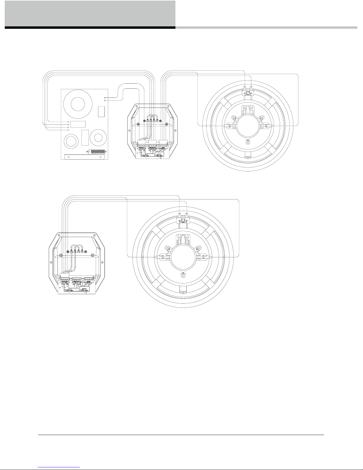
In passive (default) mode, the internal wiring is as shown in Fig. 1, with the full range signal routed through the
internal crossover and divided into separate LF and HF signals using a four pole connector.
For bi-amp operation, recongure the internal wiring as shown in Fig 2. The two-wire connector leading to
the crossover is disconnected. The four-wire connector from the speakers now bypasses the crossover and
instead connects directly to the speakON® inputs, replacing the connector that previously led to the crossover.
For bi-amp operation, the speakON® connectors coming from the amplier(s) must be wired as follows:
1 + LF +
1 - LF –
2 + HF +
2 - HF –
Note that the barrier strip terminals are wired for passive full-range operation only.
Page 8
8. Equalisation
8
VX Series Operation Manual rev 1.1.2
Fig 1.
Fig 2.
Page 9

8. Equalisation
VX Series Operation Manual rev 1.1.2
9
8. Equalisation
VX Series loudspeakers require no equalisation or correction to overcome system limitations; equalisation
is necessary only to compensate for difcult acoustic environments. Over-equalisation can reduce system
headroom and introduce phase distortion, resulting in degraded sound. If equalisation is required, it should
be applied gently and smoothly. Because VX Series loudspeakers are point source, phase coherent designs,
excessive equalization usually proves detrimental to the overall sound quality.
When one loudspeaker is used in close proximity to another, comb ltering effects can create coverage problems.
(Comb ltering creates an uneven frequency response across the coverage area due to constructive and
destructive interference effects between the two sources.) Comb ltering cannot be cured by equalisation;
this should be addressed with proper arraying as discussed in the following section.
Page 10

9. Arraying
10
VX Series Operation Manual rev 1.1.2
9. Arraying
Small alterations to loudspeaker positions can have the effect of minimising problematic combing frequencies.
Arrays should be constructed so that the individual coverage patters of each loudspeaker combine with
minimal overlap. The design of the VXP cabinet greatly simplies the creation of effective arrays, allowing
seamless wide horizontal coverage using two loudspeakers without the need for tedious experimentation.
By placing the VXP cabinets with the 30 degree angled rear panels together, minimal dispersion pattern
overlap is achieved, guaranteeing an extraordinarily smooth transition. In many applications the 90 or 75
degree dispersion pattern may be sufcient in the horizontal plane. It is also possible to stack the cabinets
vertically using the above method (in a central cluster for example) where greater vertical dispersion is required.
As shown in the above diagram, one of the VXP cabinets is inverted to allow the optimum splay angle to be
achieved. The grille can be simply removed from this cabinet and be replaced for matching orientation. The
grille is held in position by the two xing screws on the top and bottom lips of the cabinet.
Page 11

10. Dimensions
VX Series Operation Manual rev 1.1.2
11
10. Dimensions
333.0
[13.11"]
225.0
[8.86"]
215.0
[8.46"]
50.8
[2.00"]
37.0
[1.46"]
107.9
[4.25"]
75°
75°
115.0
[4.53"]
180.0
[7.09"]
333.0
1"]
200.0
[7.87"]
125.0
[4.92"]
75°
75°
37.0
[1.46"]
107.9
[4.25"]
50.8
[2.00"]
VX 5.2
VX 6
Page 12

10. Dimensions
12
VX Series Operation Manual rev 1.1.2
388.0
[15.28"]
280.0
[11.02"]
275.0
[10.83"]
50.8
[2.00"]
94.0
[3.70"]
107.9
[4.25"]
180.0
[7.09"]
135.0
[5.31"]
60°
60°
280.0
[11.02"]
590.0
[23.23"]
145.0
[5.71"]
60°
60°
180.0
[7.09"]
328.0
[12.91"]
140.0
[5.51"]
VX 8
VX 8.2
Page 13

10. Dimensions
VX Series Operation Manual rev 1.1.2
13
VX 12
VX 12 HP
370.0
[14.57"]
360.0
[14.17"]
155.0
[6.10"]
224.0
[8.82"]
180.0
[7.09"]
290.0
[11.42"]
190.0
[7.48"]
60°
40°
486.0
[19.13"]
180.0
[7.09"]
406.0
[15.98"]
127.0
[5.00"]
70.0
[2.76"]
370.0
[14.57"]
360.0
[14.17"]
180.0
[7.09"]
290.0
[11.42"]
190.0
[7.48"]
60°
40°
486.0
[19.13"]
180.0
[7.09"]
406.0
[15.98"]
70.0
[2.76"]
155.0
[6.10"]
127.0
[5.00"]
224.0
[8.82"]
Page 14

11. Rigging and Safety Procedures
14
VX Series Operation Manual rev 1.1.2
780.0
[30.71"]
370.0
[14.57"]
190.0
[7.48"]
155.0
[6.10"]
40.0
[1.57"]
155.0
[6.10"]
180.0
[7.09"]
40.0
[1.57"]
290.0
[11.42"]
180.0
[7.09"]
190.0
[7.48"]
60°
40°
292.0
[11.50"]
VX 12Q
VX 12.2Q
Page 15

11. Rigging and Safety Procedures
VX Series Operation Manual rev 1.1.2
15
VX 15HP
VX 15.5Q
Page 16

11. Rigging and Safety Procedures
16
VX Series Operation Manual rev 1.1.2
11. Rigging and Safety Procedures
The Tannoy Professional hardware covered in this guide has been designed to offer quick, simple, cost
effective and secure solutions for mounting specic Tannoy Professional loudspeakers. This hardware has been
designed and manufactured with a high safety load factor for its specic role. To ensure the safest possible use
of the hardware covered in this guide, it must be assembled in strict accordance with the instructions specied.
The information in these Operation Manuals relating to the assembly and the safe use of these accessories
must be understood and followed.
The installation of Tannoy Professional loudspeakers - using the dedicated hardware - should carried out only
by fully qualied installers, in accordance with all the required safety codes and standards that apply at the
place of installation. WARNING: As the legal requirements for mounting, suspending, hanging, ying or rigging
equipment change from country to country, please consult your local safety standards ofce before installing
any product. We also recommend that you thoroughly check any laws and bylaws prior to installation.
Tannoy Professional hardware has been designed for use with specic Tannoy Professional loudspeakers,
and is not designed or intended for use with any other Tannoy Professional products, or any other devices.
Using Tannoy Professional hardware for any purpose other than that indicated in this guide is considered to
be improper use. Such use can be very dangerous: overloading, modifying, damaging, or assembling in a
manner other than that clearly stated in the Operation will compromise safety. The component parts of any
Tannoy Professional hardware device must only be assembled using the accessory kits supplied and in strict
compliance with the Operation Manual. The use of other accessories or non-approved methods of assembly
may result in an unsafe hardware system by reducing the load safety factor. Welding, or any other method of
permanently xing hardware components together or to the integral xing points in the cabinet, should never
be used.
Whenever a Tannoy Professional loudspeaker is xed to a surface using a Tannoy Professional hardware
device, the installer must ensure that the surface is capable of safely and securely supporting the load. The
hardware employed must be safely, and securely attached both to the loudspeaker and also to the surface
in question, in accordance with the Operation Manual, using only the xing holes provided as standard and
covered in the manual. Secure xings to the building structure are vital. Seek help from architects, structural
engineers or other specialists if in any doubt. All loudspeakers own in theatres, nightclubs, conference centres
or other places of work and entertainment must be provided with an independent, correctly rated and securely
attached secondary safety restraint in addition to the principal hardware device. This secondary safety restraint
must prevent the loudspeaker from dropping more than 150 mm (6”) should the principal hardware device fail.
Page 17

11. Service Parts & Accessories
VX Series Operation Manual rev 1.1.2
17
11. Service Parts & Accessories
Model HF unit Dual driver Bass driver HF diapharagm Recone Kit
VX 5.2 79 00 0915 79 00 128 0 790 0 12 81 – –
VX 6 7900 0 683 7900 0742 – – –
VX 8 / VX 8.2 – 79 0 0 12 82 790 0 12 83 79 00 128 3 –
VX 12 – 79 0 0 128 5 – 79 0 0 128 7 7900 0441
VX 12HP – 79 0 0 128 9 – 7900 1292 79 00 0 716
VX 12Q – 7900 1290 – 7900 1292 79 00 0716
VX 12.2Q – 7900 1290 79 00 1291 7900 1292 79 00 0716
VX 15HP – 79 0 0 12 93 – 7900 1292 7900 064 6
VX 15Q – 79 0 0 12 94 – 7900 1292 7900 064 6
Page 18

12. Technical Specifications
18
VX Series Operation Manual rev 1.1.2
Model VX 5. 2 VX 6 VX 8
Performance
Frequency Response (-3 dB)
1)
87 Hz – 35 Hz 92 Hz – 35 Hz 85 Hz – 35 Hz
Frequency Range (-10 dB) 1 65 Hz – 45kHz 80 Hz – 45kHz 62 Hz – 45 kHz
System Sensitivity (1 W @1 m)
2)
90 dB (1 W = 2.83 V for 8 ohms) 91 dB (1 W = 2.83 V for 8 ohms) 92 dB (1 W = 2.83 V for 8 ohms)
Dispersion (degrees conical) 120 degrees (H) x 90 degrees (V) 90 degrees conical 90 degrees conical
Driver Complement 1 x 125 mm (5.00”) constant 1 x 150 mm (6.00”) constant 1 x 200 mm (8.00”) constant
directivity Dual Concentric directivity Dual Concentric directivity Dual Concentric
1 x 125mm (5.00”) bass driver
Crossover Passive 2.0 kHz Passive 2.0 kHz Passive 1.7 kHz
with dynamic HF protection with dynamic HF protection with dynamic HF protection
Directivity Factor (Q) 7.3 (averaged 1 kHz to 8 kHz) 5.6 averaged 1 kHz to 10 kHz 6.8 averaged 1kHz to 10kHz
Directivity Index (DI) 8.6 (averaged 1 kHz to 8 kHz) 7.0 averaged 1 kHz to 10 kHz 7.9 averaged 1kHz to 10kHz
Rated Ma ximum SPL (2) Average: 111 dB Average: 111 dB Average: 113 dB
Peak: 117 dB Peak: 117 dB Peak: 119 dB
Power Handling Average: 130 W Average: 100 W Average: 130 W
Programme: 260 W Programme: 200 W Programme: 260 W
Peak: 520 W Peak: 400 W Peak: 520 W
Recommended Amplier Power 260 W @ 8 ohms 200 W @ 8 ohms 260 W @ 8 ohms
Nominal Impedance 8 ohms 8 ohms 8 ohms
Distortion
10% Full Power (10.2 V) 2nd Harmonic 3rd Harmonic 2nd Harmonic 3rd Harmonic 2nd Harmonic 3rd Harmonic
250 Hz 2.85% 0.52% 2.64% 0.365% 0.12% 0.15%
1 kHz 0.56% 0.31% 0.223% 0.458% 0.23% 0.84%
10 kHz 1.24% 0.15 % 1.873% 0.29% 1.35% 0.16%
Distortion
10% Full Power (10.2 V) 2nd Harmonic 3rd Harmonic 2nd Harmonic 3rd Harmonic 2nd Harmonic 3rd Harmonic
250 Hz 0.70% 0.17% 0.64% 0.314% 0.16% 0.14%
1 kHz 0.08% 0.26% 0.062% 0.436% 0.09% 0.53%
10 kHz 0.41% 0.10% 0.78% 0.266% 0.53% 0.17%
Construction
Enclosure 6.73 litre birch plywood, vented 9.16 litre birch plywood, vented 16.28 litre, 15 mm (0.62”) birch plywood,
and internally brace and internally brace vented and internally braced.
Finish Textured black or white paint, Textured black or white paint, Textured black or white paint,
with custom colours on request. with custom colours on request. with custom colours on request.
Powder coated perforated steel grille Powder coated perforated steel grille Powder coated perforated steel grille
Airnet cloth behind Airnet cloth behind Airnet cloth behind
Connectors 1 x speakON NL4MP, 1 x speakON NL4MP, 1 x speakON NL4MP,
2 x 4 mm binding posts 2 x 4 mm binding posts 2 x 4 mm binding posts
Fittings 2 x M6 yoke bracket inserts,
Fixings compatible with Omnimount
TM
and PowerdriveTM style brackets
2 x M6 yoke bracket inserts, Blanking
plate for optional VTH pole mount
Fixings compatible with Omnimount
TM
and PowerdriveTM style brackets
4 x M10 yoke bracket inserts
1 x Integrip carrying handle
Blanking plate for optional VTH pole
mount.
Fixings compatible with Omnimount
TM
and PowerdriveTM style brackets
Dimensions (H x W x D) W: 180 mm (7.1”), W: 225 mm (8.9”), W: 280 mm (11.0”),
H: 333 mm (13.1”), H: 333 mm (13.1”), H: 338 mm (15.3”),
D: 200 mm (7.9”) D: 215 mm (8.1”) D: 275 mm (10.8”)
Net Weight 5.0 kg (11.0 lbs) 5.5 kg (12.1 lbs) 8.5 kg (18.7 lbs)
Shipped Weight 10.5 kg (23.1 lbs) 12.5 kg (27.6 lbs) 18.5 kg (40.8 lbs)
Packed Quantity 2 2 2
v
12. Technical Specifications
Following are the VX Series technical specications. These gures are accurate at the time of printing but please note that all gures are
subject to change without notice.
(1) Average over stated bandwidth. Measured at 1 metre on axis in an anechoic chamber.
(2) Unweighted pink noise input, measured at 1 metre in an anechoic chamber.
A full range of measurements, performance data, and EaseTM Data can be downloaded from www.tannoy.com.
Tannoy operates with a policy of continuous research and development. Product performance always will equal or exceed published specications. However, following introduction of new
materials or manufacturing methods, Tannoy reserves the right to alter specications without prior notice.
Page 19

12. Technical Specifications
VX Series Operation Manual rev 1.1.2
19
Model VX 8.2 VX 12
Performance
Frequency Response (-3 dB)
1)
80 Hz – 35 Hz 70 Hz – 25 Hz
Frequency Range (-10 dB) 1 60 Hz – 45 kHz 55 Hz – 38 kHz
System Sensitivity (1 W @1 m)
2)
93 dB (1 W = 2.83 V for 8 ohms) 97 dB (1 W = 2.83 V for 8 ohms)
Dispersion (degrees conical) 90 degrees conical 90 degrees conical
Driver Complement 1 x 200 mm (8.00”) constant 1 x 305 mm (12.00”) constant
directivity Dual Concentric directivity Dual Concentric
1 x 200mm (8.00”) bass driver
Crossover Passive 360 Hz and 1.5 kHz Passive 1 kHz with HF protection
with dynamic HF protection
Directivity Factor (Q) 8.1 (averaged 1 kHz to 8 kHz) 9.6 (averaged 1 kHz to 8 kHz)
Directivity Index (DI) 9.2 (averaged 1 kHz to 8 kHz) 9.8 (averaged 1 kHz to 8 kHz)
Rated Ma ximum SPL (2) Average: 116 dB Average: 120 dB
Peak: 122 dB Peak: 126 dB
Power Handling Average: 200 W Average: 200 W
Programme: 400 W Programme: 400 W
Peak: 800 W Peak: 800 W
Recommended Amplier Power 400 W @ 8 ohms 400 W @ 8 ohms
Nominal Impedance 8 ohms 8 ohms
Distortion
10% Full Power (10.2 V) 2nd Harmonic 3rd Harmonic 2nd Harmonic 3rd Harmonic
250 Hz 0.58% 0.34% 0.52% 0.58%
1 kHz 0.34% 0.69% 2.98% 0.63%
10 kHz 1.73% 0.15% 3.58% 0.19%
Distortion
10% Full Power (10.2 V) 2nd Harmonic 3rd Harmonic 2nd Harmonic 3rd Harmonic
250 Hz 0.15% 0.15% 0.10% 0.26%
1 kHz 0.11% 0.37% 0.81% 0.58%
10 kHz 0.74% 0.22% 1.18% 0.03%
Construction
Enclosure 24.97 litre, 15 mm (0.62”) birch plywood, 36.07 litre, 15 mm (enclosure)
vented and internally braced. and 18 mm (front) birch plywood
vented and internally braced
Finish Textured black or white paint, Textured black or white paint,
with custom colours on request. with custom colours on request.
Powder coated perforated steel grille Powder coated perforated steel grille
Airnet cloth behind Airnet cloth behind
Connectors 2 x speakON NL4MP 2 x speakON NL4MP
and Barrier strip and Barrier strip
Fittings 4 x M10 yoke bracket inserts
2 x Integrip carrying handles
Blanking plate for optional VTH pole
mount
8 x M10 Flying inserts (portrait or
landscape mounting), 8 x M10 yoke
bracket inserts
2 x Integrip carrying handles
Blanking plate for optional VTH pole
mount
Fixings compatible with Omnimount
TM
and PowerdriveTM style brackets
Dimensions (H x W x D) W: 280 mm (11.0”), W: 370 mm ( 14.6”),
H: 590 mm (23.2”), H: 486 mm (19.1”),
D: 275 mm (10.8”) D: 360 mm (14.1”)
Net Weight 15.5 kg (34.2 lbs) 17.0 kg (37.5 lbs)
Shipped Weight 17.5 kg (38.6 lbs) 19.5 kg (43.0 lbs
Packed Quantity 1 1
(1) Average over stated bandwidth. Measured at 1 metre on axis in an anechoic chamber.
(2) Unweighted pink noise input, measured at 1 metre in an anechoic chamber.
A full range of measurements, performance data, and EaseTM Data can be downloaded from www.tannoy.com.
Tannoy operates with a policy of continuous research and development. Product performance always will equal or exceed published specications. However, following introduction of new
materials or manufacturing methods, Tannoy reserves the right to alter specications without prior notice.
Page 20

12. Technical Specifications
20
VX Series Operation Manual rev 1.1.2
Model VX 12HP VX 12Q V X 12.2 Q
Performance
Frequency Response (-3 dB)
1)
80 Hz – 25 Hz 80 Hz – 25 Hz 70 Hz – 25 Hz
Frequency Range (-10 dB) 1 60 Hz – 30 kHz 60 Hz – 30 kHz 55 Hz – 30 kHz
System Sensitivity (1 W @1 m)
2)
Passive - Full Range 97 dB (1W = 2.83 V for 8 ohms) 97 dB (1W = 2.83 V for 8 ohms) 99 dB (1W = 2.83 V for 8 Ohms)
Biamp (LF) 98 dB 98 dB 98 dB
Biamp (LF) 106 dB 108 dB 102 dB
Dispersion (degrees conical) 75 degrees conical 75 degrees (H) x 40 degrees (V) 75 degrees (H) x 40 degrees (V)
Driver Complement 1 x 305 mm (12.00”) 1 x 305 mm (12.00”) PowerDual™ 1 x 305 mm (12.00”) PowerDual™
constant directivity PowerDual™ with Q-Centric waveguide with Q-Centric waveguide
1 x 305 mm (12.00”) bass driver
Crossover Passive 1 kHz Passive 1.5 kHz Passive 300 Hz and 1.5 kHz
Product can be recongured for Product can be recongured for Product can be recongured for
bi-amped operation. Bi-amp bi-amped operation. Bi-amp bi-amped operation. Bi-amp
system parameters in Operation Manual system parameters in Operation Manual system parameters in Operation Manual
Directivity Factor (Q) 10.1 (averaged 1 kHz to 10 kHz) 13.0 (averaged 1 kHz to 8 kHz) 13.0 (averaged 1 kHz to 8 kHz)
Directivity Index (DI) 10.0 (averaged 1 kHz to 10kHz) 11.1 (averaged 1 kHz to 8 kHz) 11.1 (averaged 1 kHz to 8 kHz)
Rated Ma ximum SPL (2)
Passive - Full Range 123 dB (average) 129 dB (peak) 123 dB (average) 129 dB (peak) 126 dB (average) 132 dB (peak)
Biamp (LF ) 124 dB (average) 130 dB (peak) 124 dB (average) 130 dB (peak) 123 dB (average) 129 dB (peak)
Biamp (HF ) 125 dB (average) 131 dB (peak) 127 dB (average) 132 dB (peak) 127 dB (average) 133 dB (peak)
Power Handling
Passive - Full Range Average: 350 W Average: 350 W Average: 500 W
Programme: 700 W Programme: 700 W Programme: 1000 W
Peak: 1400 W Peak: 1400 W Peak: 2000 W
Biamp (LF ) Average: 350 W Average: 350 W Average: 350 W
Programme: 700 W Programme: 700 W Programme: 700 W
Peak: 1400 W Peak: 1400 W Peak: 1400 W
Biamp (HF ) Average: 80 W Average: 80 W Average: 350 W
Programme: 160 W Programme: 160 W Programme: 700 W
Peak: 320 W Peak: 320 W Peak: 1400 W
Recommended Amplier Power
Passive - Full Range 700 W @ 8 ohms 700 W @ 8 ohms 1000 W @ 8 ohms
Biamp (LF ) 700 W @ 8 ohms 700 W @ 8 ohms 700 W @ 8 ohms
Biamp (HF ) 160 W @ 8 ohms 160 W @ 8 ohms 700 W @ 8 ohms
Nominal Impedance 8 ohms 8 ohms 8 ohms
Distortion
10% Full Power (10.2 V) 2nd Harmonic 3rd Harmonic 2nd Harmonic 3rd Harmonic 2nd Harmonic 3rd Harmonic
250 Hz 0.239% 0.67% 0.72% 0.17% 2.49% 0.49%
1 kHz 1.58% 2.53% 0.57% 0.76% 0.54% 0.73%
10 kHz 5.2% 0.161% 5.11% 0.08% 7.54% 0.80%
Distortion
10% Full Power (10.2 V) 2nd Harmonic 3rd Harmonic 2nd Harmonic 3rd Harmonic 2nd Harmonic 3rd Harmonic
250 Hz 0.11% 0.581% 0.16% 0.19% 0.60% 0.21%
1 kHz 0.79% 2.53% 0.18% 0.49% 0.20% 0.49%
10 kHz 1.94% 0.161 1.63% 0.08% 2.56% 0.10%
Construction
Enclosure 36.07 litre, 15 mm (enclosure) and 36.07 litre, 15 mm (enclosure) and 59.08 litre, 15 mm (enclosure) and
18 mm (front) birch plywood, 18 mm (front) birch plywood, 18 mm (front) birch plywood,
vented and internally braced vented and internally braced vented and internally braced
Finish Textured black or white paint, Textured black or white paint, Textured black or white paint,
with custom colours on request. with custom colours on request. with custom colours on request.
Powder coated perforated steel grille Powder coated perforated steel grille Powder coated perforated steel grille
Airnet cloth behind Airnet cloth behind Airnet cloth behind
Connectors 2 x speakON NL4MP and Barrier strip 2 x speakON NL4MP and Barrier strip 2 x speakON NL4MP and Barrier strip
Fittings 8 x M10 Flying inserts (portrait or
landscape mounting), 8 x M10 yoke
bracket inserts
2 x Integrip carrying handles
Blanking plate for optional VTH pole
mount
Fixings compatible with Omnimount
TM
and PowerdriveTM style brackets
8 x M10 Flying inserts (portrait or
landscape mounting), 8 x M10 yoke
bracket inserts
2 x Integrip carrying handles
Blanking plate for optional VTH pole
mount
Fixings compatible with Omnimount
TM
and PowerdriveTM style brackets
8 x M10 corner ying inserts, 8 x
M10 yoke bracket inserts
2 x Integrip carrying handles
Blanking plate for optional VTH pole
mount
Dimensions (H x W x D) W: 370 mm ( 14.6”), W: 370 mm ( 14.6”), W: 370 mm ( 14.6”),
H: 486 mm (19.1”), H: 486 mm (19.1”), H: 780 mm (30.7”),
D: 360 mm (14.1”) D: 360 mm (14.1”) D: 360 mm (14.1”)
Net Weight 21.5 kg (47.4 lbs) 21.0 kg (46.3 lbs) 33.5 kg (73.9 lbs)
Shipped Weight 23.5 kg (51.8 lbs) 23.0 kg (50.7 lbs) 36.5 kg (80.5 lbs)
Packed Quantity 1 1 1
13. Technical Specifications
(1) Average over stated bandwidth. Measured at 1 metre on axis in an anechoic chamber.
(2) Unweighted pink noise input, measured at 1 metre in an anechoic chamber.
A full range of measurements, performance data, and EaseTM Data can be downloaded from www.tannoy.com.
Tannoy operates with a policy of continuous research and development. Product performance always will equal or exceed published specications. However, following introduction of new
materials or manufacturing methods, Tannoy reserves the right to alter specications without prior notice.
Page 21

12. Technical Specifications
VX Series Operation Manual rev 1.1.2
21
Model VX 15HP VX 15Q
Performance
Frequency Response (-3 dB)
1)
70 Hz – 25 Hz 70 Hz – 25 Hz
Frequency Range (-10 dB) 1 58 Hz – 30` kHz 58 Hz – 30 kHz
System Sensitivity (1 W @1 m)
2)
Passive - Full Range 99 dB (1 W = 2.83 V for 8 ohms) 99 dB (1W = 2.83 V for 8 ohms)
Biamp (LF) 100 dB 100 dB
Biamp (LF) 106 dB 108 dB
Dispersion (degrees conical) 75 degrees conical 75 degrees (H) x 40 degrees (V)
Driver Complement 1 x 380 mm (15.00”) 1 x 380 mm (15.00”) PowerDual™
constant directivity PowerDual™ with Q-Centric waveguide
Crossover Passive 1.3 kHz Passive 1.3 kHz
Product can be recongured for Product can be recongured for
bi-amped operation. Bi-amp bi-amped operation. Bi-amp
system parameters in Operation Manual system parameters in Operation Manual
Directivity Factor (Q) 9.7 (averaged 1 kHz to 8 kHz) 12.0 (averaged 1 kHz to 8 kHz)
Directivity Index (DI) 9.9 (averaged 1 kHz to 8 kHz) 10.8 (averaged 1 kHz to 8 kHz)
Rated Ma ximum SPL (2)
Passive - Full Range 125 dB (average) 131 dB (peak) 125 dB (average) 131 dB (peak)
Biamp (LF ) 126 dB (average) 132 dB (peak) 126 dB (average) 132 dB (peak)
Biamp (HF ) 125 dB (average) 131 dB (peak) 127 dB (average) 132 dB (peak)
Power Handling
Passive - Full Range Average: 400 W Average: 400 W
Programme: 800 W Programme: 800 W
Peak: 1600 W Peak: 1600 W
Biamp (LF ) Average: 400 W Average: 400 W
Programme: 800 W Programme: 800 W
Peak: 1600 W Peak: 1600 W
Biamp (HF ) Average: 80 W Average: 80 W
Programme: 160 W Programme: 160 W
Peak: 320 W Peak: 320 W
Recommended Amplier Power
Passive - Full Range 800 W @ 8 ohms 800 W @ 8 ohms
Biamp (LF ) 800 W @ 8 ohms 800 W @ 8 ohms
Biamp (HF ) 160 W @ 8 ohms 160 W @ 8 ohms
Nominal Impedance 8 ohms 8 ohms
Distortion
10% Full Power (10.2 V) 2nd Harmonic 3rd Harmonic 2nd Harmonic 3rd Harmonic
250 Hz 1.0% 0.56% 1.05% 0.10%
1 kHz 1.4% 1.0% 1.61% 1.02%
10 kHz 3.9% 1.8% 7.79% 1.15%
Distortion
10% Full Power (10.2 V) 2nd Harmonic 3rd Harmonic 2nd Harmonic 3rd Harmonic
250 Hz 0.31% 0.45% 0.30% 0.06%
1 kHz 0.45% 0.79% 0.58% 0.52%
10 kHz 3.16% 0.32% 2.32% 0.13%
Construction
Enclosure 57.82 litre, 18 mm birch plywood, 57.82 litre, 18 mm birch plywood,
vented and internally braced. vented and internally braced.
Finish Textured black or white paint, Textured black or white paint,
with custom colours on request. with custom colours on request.
Powder coated perforated steel grille Powder coated perforated steel grille
Airnet cloth behind Airnet cloth behind
Connectors 2 x speakON NL4MP and Barrier strip 2 x speakON NL4MP and Barrier strip
Fittings 8 x M10 corner ying inserts, 8 x M10
yoke bracket inserts
2 x Integrip carrying handles
Blanking plate for optional VTH pole
mount
Fixings compatible with Omnimount
TM
and PowerdriveTM style brackets
8 x M10 corner ying inserts, 8 x
M10 yoke bracket inserts
2 x Integrip carrying handles
Blanking plate for optional VTH pole
mount
Fixings compatible with Omnimount
TM
and PowerdriveTM style brackets
Dimensions (H x W x D) W: 450 mm ( 17.7”), W: 450 mm (17.7”),
H: 590 mm (23.2”), H: 590 mm (23.2”),
D: 420 mm (16.5”) D: 420 mm (16.5”)
Net Weight 26.5 kg (58.4 lbs) 27.0 kg (59.5 lbs)
Shipped Weight 29.5 kg (65.0 lbs) 29.5 kg (65.0 lbs)
Packed Quantity 1 1
(1) Average over stated bandwidth. Measured at 1 metre on axis in an anechoic chamber.
(2) Unweighted pink noise input, measured at 1 metre in an anechoic chamber.
A full range of measurements, performance data, and EaseTM Data can be downloaded from www.tannoy.com.
Tannoy operates with a policy of continuous research and development. Product performance always will equal or exceed published specications. However, following introduction of new
materials or manufacturing methods, Tannoy reserves the right to alter specications without prior notice.
Page 22

13. Warranty
22
VX Series Operation Manual rev 1.1.2
13. Warranty
No maintenance of the VX Series loudspeakers is necessary.
All Tannoy VX Series professional loudspeaker products are covered by a 5 year warranty from the date of
manufacture, subject to the absence of misuse, overload or accidental damage. Claims will not be considered
if the serial number has been altered or removed. Work under warranty should only be carried out by a
Tannoy Professional dealer or service agent. This warranty in no way affects your statutory rights. For further
information please contact your dealer or distributor in your country. If you cannot locate your distributor please
contact Customer Services, Tannoy Ltd at the address given below or check at www.tannoy.com
Customer Services, Tannoy Ltd., Rosehall Industrial Estate, Coatbridge, Strathclyde, ML5 4TF, Scotland
Telephone: 01236 420199 (National) +44 1236 420199 (International)
Fax: 01236 428230 (National) +44 1236 428230 (International)
E-Mail: prosales@tannoy.com
Do not ship any product to Tannoy without previous authorisation.
Tannoy is committed to a policy of continuous product improvements through research and development.
Though performance will equal or exceed published specications, new materials or manufacturing processes
could introduce variances. For extremely critical applications, please conrm current specications with
your supplier.
Page 23

14. Declaration of Conformity
VX Series Operation Manual rev 1.1.2
23
14. Declaration of Conformity
The following apparatus is/are manufactured in the United Kingdom by Tannoy Ltd of Rosehall Industrial Estate,
Coatbridge, Scotland, ML5 4TF and conform(s) to the protection requirements of the European Electromagnetic
Compatibility Standards and Directives relevant to Domestic Electrical Equipment. The apparatus is designed
and constructed such that electromagnetic disturbances generated do not exceed levels allowing radio
and telecommunications equipment and other apparatus to operate as intended, and, the apparatus has
an adequate level of intrinsic immunity to electromagnetic disturbance to enable operation as specied and
intended.
Details of the Apparatus: Tannoy Contractor Loudspeaker
Model Number: VX SERIES
Associated Technical File: EMCVX SERIES
Applicable Standards: EN 50081-1 Emission
EN 50082-1 Immunity
Electrical Safety: EN 60065
Engineering Director – Professional Products, Tannoy Professional
12 /07/2011
Page 24

tannoypro.com
6481 0592/290114
Tannoy operates a policy of continuous research and development. The introduction of new materials or manufacturing
methods will always equal or exceed the published specications. All specications are subject to change without notice.
Copyright (c) 2014 Tannoy Limited. All rights reserved.
 Loading...