


Quick Start Guide
VQ 100/VQ 60
3 Way Dual 12" Large Format Loudspeaker for High Performance Installation Applications
VQ 85DF/VQ 64DF
2 Way Down-Firing Dual Concentric Mid-High Loudspeaker for High Performance Installation
Applications
VQ 64MH
2 Way Dual Concentric Mid-High Large Format Loudspeaker for High Performance Installation
Applications
VQ MB
Dual 12" Mid-Bass Large Format Loudspeaker for High Performance Installation Applications
V 1.0

2 VQ Series Quick Start Guide 3
8. No instale este equipo cerca de fuentes de calor
los recursos naturales. Para más información acerca del
deben ser siempre eliminadas en un punto limpio y nunca
9. Do not defeat the safety purpose of the polarized
20. Please keep the environmental aspects of battery
This apparatus may be used in tropical and moderate
Microphones and Coolaudio are trademarks or registered
Important Safety
Instructions
Terminals marked with this symbol carr y
electrical current of sucient magnitude
to constitute risk of electric shock.
Use only high-quality professional speaker cables with
¼" TS or twist-locking plugs pre-installed. Allother
installation or modication should be performed only
by qualiedpersonnel.
This symbol, wherever it appears,
alertsyou to the presence of uninsulated
dangerous voltage inside the
enclosure-voltage that may be sucient to constitute a
risk ofshock.
This symbol, wherever it appears,
alertsyou to important operating and
maintenance instructions in the
accompanying literature. Please read the manual.
Caution
To reduce the risk of electric shock, donot
remove the top cover (or the rear section).
No user serviceable parts inside. Refer servicing to
qualied personnel.
Caution
To reduce the risk of re or electric shock,
do not expose this appliance to rain and
moisture. The apparatus shall not be exposed to dripping
or splashing liquids and no objects lled with liquids,
suchas vases, shall be placed on the apparatus.
Caution
These service instructions are for use
by qualied service personnel only.
Toreduce the risk of electric shock do not per form any
servicing other than that contained in the operation
instructions. Repairs have to be performed by qualied
servicepersonnel.
1. Read these instructions.
2. Keep these instructions.
3. Heed all warnings.
4. Follow all instructions.
5. Do not use this apparatus near water.
6. Clean only with dry cloth.
7. Do not block any ventilation openings. Install in
accordance with the manufacturer’s instructions.
8. Do not install near any heat sources such as
radiators, heat registers, stoves, or other apparatus
(including ampliers) that produce heat.
or grounding-type plug. A polarized plug has two blades
with one wider than the other. A grounding-type plug
has two blades and a third grounding prong. The wide
blade or the third prong are provided for your safety. Ifthe
provided plug does not t into your outlet, consult an
electrician for replacement of the obsolete outlet.
10. Protect the power cord from being walked on or
pinched particularly at plugs, convenience receptacles,
and the point where they exit from the apparatus.
11. Use only attachments/accessories specied by
themanufacturer.
12. Use only with the
cart, stand, tripod, bracket,
or table specied by the
manufacturer, orsold with
the apparatus. When a cart
is used, use caution when
moving the cart/apparatus
combination to avoid
injury from tip-over.
13. Unplug this apparatus during lightning storms or
when unused for long periods of time.
14. Refer all servicing to qualied service personnel.
Servicing is required when the apparatus has been
damaged in any way, such as power supply cord or plug
is damaged, liquid has been spilled or objects have fallen
into the apparatus, the apparatus has been exposed
to rain or moisture, does not operate normally, or has
beendropped.
15. The apparatus shall be connected to a MAINS socket
outlet with a protective earthing connection.
16. Where the MAINS plug or an appliance coupler is
used as the disconnect device, the disconnect device shall
remain readily operable.
17. Correct disposal of this
product: This symbol indicates
that this product must not be
disposed of with household
waste, according to the WEEE
Directive (2012/19/EU) and
your national law. This product
should be taken to a collection center licensed for the
recycling of waste electrical and electronic equipment
(EEE). The mishandling of this type of waste could have
a possible negative impact on the environment and
human health due to potentially hazardous substances
that are generally associated with EEE. At the same time,
your cooperation in the correct disposal of this product
will contribute to the ecient use of natural resources.
For more information about where you can take your
waste equipment for recycling, please contact your local
city oce, or your household waste collection service.
18. Do not install in a conned space, such as a book
case or similar unit.
19. Do not place naked ame sources, such as lighted
candles, on the apparatus.
disposal in mind. Batteries must be disposed-of at a
battery collection point.
21.
climates up to 45°C.
LEGAL DISCLAIMER
Music Tribe accepts no liability for any loss which may
be suered by any person who relies either wholly or in
part upon any description, photograph, or statement
contained herein. Technical specications, appearances
and other information are subject to change without
notice. All trademarks are the property of their
respective owners. Midas, Klark Teknik, Lab Gruppen,
Lake, Tannoy, Turbosound, TC Elec tronic, TC Helicon,
Behringer, Bugera, Oberheim, Auratone, Aston
trademarks of Music Tribe Global Brands Ltd. © Music
Tribe Global Brands Ltd. 2021 All rights reserved.
LIMITED WARRANTY
For the applicable warranty terms and conditions
and additional information regarding Music Tribe’s
Limited Warranty, please see complete details online at
musictribe.com/warranty.
Instrucciones de
seguridad
Las terminales marcadas con este símbolo
transportan corriente eléctrica de
magnitud suciente como para constituir
un riesgo de descarga eléctrica. Utilice solo cables de
altavoz profesionales y de alta calidad con conectores
TS de 6,3 mm o de bayoneta prejados. Cualquier otra
instalación o modicación debe ser realizada únicamente
por un técnico cualicado.
Este símbolo, siempre que aparece,
leadvierte de la presencia de voltaje
peligroso sin aislar dentro de la caja;
estevoltaje puede ser suciente para constituir un riesgo
dedescarga.
Este símbolo, siempre que aparece,
leadvierte sobre instrucciones operativas
y de mantenimiento que aparecen en la
documentación adjunta. Por favor, lea el manual.
Atención
Para reducir el riesgo de descarga
eléctrica, no quite la tapa (o la parte
posterior). No hay piezas en el interior del equipo que
puedan ser reparadas por el usuario. Si es necesario,
póngase en contacto con personal cualicado.
Atención
Para reducir el riesgo de incendio o
descarga eléctrica, no exponga este
aparato a la lluvia, humedad o alguna otra fuente que
pueda salpicar o derramar algún líquido sobre el aparato.
Nocoloque ningún tipo de recipiente para líquidos sobre
el aparato.
Atención
Las instrucciones de servicio deben
llevarlas a cabo exclusivamente personal
cualicado. Para evitar el riesgo de una descarga eléctrica,
no realice reparaciones que no se encuentren descritas
en el manual de operaciones. Lasreparaciones deben ser
realizadas exclusivamente por personalcualicado.
1. Lea las instrucciones.
2. Conserve estas instrucciones.
3. Preste atención a todas las advertencias.
4. Siga todas las instrucciones.
5. No use este aparato cerca del agua.
6. Limpie este aparato con un paño seco.
7. No bloquee las aberturas de ventilación. Instale el
equipo de acuerdo con las instrucciones del fabricante.
tales como radiadores, acumuladores de calor, estufas u
otros aparatos (incluyendo amplicadores) que puedan
producir calor.
9. No elimine o deshabilite nunca la conexión a tierra
del aparato o del cable de alimentación de corriente.
Unenchufe polarizado tiene dos polos, uno de los cuales
tiene un contacto más ancho que el otro. Una clavija con
puesta a tierra dispone de tres contactos: dos polos y la
puesta a tierra. El contacto ancho y el tercer contacto,
respectivamente, son los que garantizan una mayor
seguridad. Si el enchufe suministrado con el equipo no
concuerda con la toma de corriente, consulte con un
electricista para cambiar la toma de corriente obsoleta.
10. Coloque el cable de suministro de energía de manera
que no pueda ser pisado y que esté protegido de objetos
alados. Asegúrese de que el cable de suministro de
energía esté protegido, especialmente en la zona de la
clavija y en el punto donde sale del aparato.
11. Use únicamente los dispositivos o accesorios
especicados por el fabricante.
12. Use únicamente la
carretilla, plataforma,
trípode, soporte o mesa
especicados por el
fabricante o suministrados
junto con el equipo.
Altransportar el equipo,
tenga cuidado para evitar
daños y caídas al tropezar con algún obstáculo.
13. Desenchufe el equipo durante tormentas o si no va a
utilizarlo durante un periodo largo.
14. Confíe las reparaciones únicamente a servicios
técnicos cualicados. La unidad requiere mantenimiento
siempre que haya sufrido algún daño, si el cable de
suministro de energía o el enchufe presentaran daños,
sehubiera derramado un líquido o hubieran caído objetos
dentro del equipo, si el aparato hubiera estado expuesto
a la humedad o la lluvia, si ha dejado de funcionar de
manera normal o si ha sufrido algún golpe o caída.
15. Al conectar la unidad a la toma de corriente eléctrica
asegúrese de que la conexión disponga de una unión
atierra.
16. Si el enchufe o conector de red sirve como único
medio de desconexión, éste debe ser accesiblefácilmente.
17. Cómo debe deshacerse de
este aparato: Este símbolo indica
que este aparato no debe ser
tratado como basura orgánica,
según lo indicado en la Directiva
WEEE (2012/19/EU) y a las
normativas aplicables en su país.
En lugar de ello deberá llevarlo al punto limpio más
cercano para el reciclaje de sus elementos eléctricos/
electrónicos (EEE). Al hacer esto estará ayudando a
prevenir las posibles consecuencias negativas para el
medio ambiente y la salud que podrían ser provocadas
por una gestión inadecuada de este tipo de aparatos.
Además, el reciclaje de materiales ayudará a conser var
reciclaje de este aparato, póngase en contacto con el
Ayuntamiento de su ciudad o con el punto limpio local.
18. No instale esta unidad en un espacio muy reducido,
tal como encastrada en una librería o similar.
19. No coloque objetos con llama, como una vela
encendida, sobre este aparato.
20. Tenga presentes todas las advertencias relativas
al reciclaje y correcta eliminación de las pilas. Las pilas
con el resto de la basura orgánica.
21. Puede usar este aparato en lugares con climas
tropicales y moderados que soporten temperaturas de
hasta 45°C.
NEGACIÓN LEGAL
Music Tribe no admite ningún tipo de responsabilidad
por cualquier daño o pérdida que pudiera sufrir
cualquier persona por conar total o parcialmente en
la descripciones, fotografías o armaciones contenidas
en este documento. Las especicaciones técnicas,
imágenes y otras informaciones contenidas en este
documento están sujetas a modicaciones sin previo
aviso. Todas las marcas comerciales que aparecen
aquí son propiedad de sus respectivos dueños. Midas,
Klark Teknik, Lab Gruppen, Lake, Tannoy, Turbosound,
TC Electronic, TC Helicon, Behringer, Bugera, Oberheim,
Auratone, Aston Microphones y Coolaudio son marcas
comerciales o marcas registradas de Music Tribe
Global Brands Ltd. © Music Tribe Global Brands Ltd.
2021 Reservados todos los derechos.
GARANTÍA LIMITADA
Si quiere conocer los detalles y condiciones aplicables
de la garantía así como información adicional sobre la
Garantía limitada de Music Tribe, consulte online toda la
información en la web musictribe.com/warranty.
4 VQ Series Quick Start Guide 5
Erdungskontakt dient Ihrer Sicherheit. Falls das
19. Stellen Sie keine Gegenstände mit oenen
Fotos oder Aussagen verlassen haben. Technische Daten,
Turbosound, TC Electronic, TC Helicon, Behringer, Bugera,
8. Ne placez pas l’appareil à proximité d’une source
dangereuses généralement associées à ces équipements.
Consignes de sécurité
Les points repérés par ce symbole portent
une tension électrique susante pour
constituer un risque d’électrocution.
Utilisez uniquement des câbles d’enceintes professionnels
de haute qualité avec ches Jack mono 6,35 mm ou ches
à verrouillages déjà installées. Touteautre installation ou
modication doit être eectuée uniquement par un
personnel qualié.
Ce symbole avertit de la présence d’une
tension dangereuse et non isolée à
l’intérieur de l’appareil - elle peut
provoquer des chocs électriques.
Attention
Ce symbol signale les consignes
d’utilisation et d’entre ! Tien importantes
dans la documentation fournie. Lisez les consignes de
sécurité du manuel d’utilisation de l’appareil.
Attention
Pour éviter tout risque de choc électrique,
ne pas ouvrir le capot de l’appareil ni
démonter le panneau arrière. L’intérieur de l’appareil
ne possède aucun élément réparable par l’utilisateur.
Laissertoute réparation à un professionnel qualié.
Attention
Pour réduire les risques de feu et de choc
électrique, n’exposez pas cet appareil à la
pluie, à la moisissure, aux gouttes ou aux éclaboussures.
Ne posez pas de récipient contenant un liquide sur
l’appareil (un vase par exemple).
Attention
Ces consignes de sécurité et d’entretien
sont destinées à un personnel qualié.
Pouréviter tout risque de choc électrique, n’eectuez
aucune réparation sur l’appareil qui ne soit décrite par le
manuel d’utilisation. Les éventuelles réparations doivent
être eectuées uniquement par un technicien spécialisé.
1. Lisez ces consignes.
2. Conservez ces consignes.
3. Respectez tous les avertissements.
4. Respectez toutes les consignes d’utilisation.
5. N’utilisez jamais l’appareil à proximité d’un liquide.
6. Nettoyez l’appareil avec un chion sec.
7. Veillez à ne pas empêcher la bonne ventilation
de l’appareil via ses ouïes de ventilation. Respectezles
consignes du fabricant concernant l’installation
del’appareil.
de chaleur telle qu’un chauage, une cuisinière ou tout
appareil dégageant de la chaleur (y compris un ampli
depuissance).
9. Ne supprimez jamais la sécurité des prises bipolaires
ou des prises terre. Les prises bipolaires possèdent deux
contacts de largeur diérente. Leplus large est le contact
de sécurité. Les prises terre possèdent deux contacts plus
une mise à la terre servant de sécurité. Si la prise du bloc
d’alimentation ou du cordon d’ali-mentation fourni ne
correspond pas à celles de votre installation électrique,
faites appel à un électricien pour eectuer le changement
de prise.
10. Installez le cordon d’alimentation de telle façon
que personne ne puisse marcher dessus et qu’il soit
protégé d’arêtes coupantes. Assurez-vous que le cordon
d’alimentation est sufsamment protégé, notamment au
niveau de sa prise électrique et de l’endroit où il est relié à
l’appareil; cela est également valable pour une éventuelle
rallonge électrique.
11. Utilisez exclusivement des accessoires et des
appareils supplémentaires recommandés par lefabricant.
12. Utilisez
exclusivement des
chariots, des diables,
desprésentoirs, despieds
et des surfaces de
travail recommandés
par le fabricant ou
livrés avec le produit.
Déplacezprécautionneusement tout chariot ou diable
chargé pour éviter d’éventuelles blessures en cas dechute.
13. Débranchez l’appareil de la tension secteur en cas
d’orage ou si l’appareil reste inutilisé pendant une longue
période de temps.
14. Les travaux d’entretien de l’appareil doivent
être eectués uniquement par du personnel qualié.
Aucunentretien n’est nécessaire sauf si l’appareil est
endommagé de quelque façon que ce soit (dommagessur
le cordon d’alimentation ou la prise par exemple), siun
liquide ou un objet a pénétré à l’intérieur du châssis, si
l’appareil a été exposé à la pluie ou à l’humidité, s’il ne
fonctionne pas correctement ou à la suite d’une chute.
15. L’appareil doit être connecté à une prise secteur
dotée d’une protection par mise à la terre.
16. La prise électrique ou la prise IEC de tout appareil
dénué de bouton marche/arrêt doit rester accessible
enpermanence.
17. Mise au rebut appropriée de
ce produit: Ce symbole indique
qu’en accord avec la directive DEEE
(2012/19/EU) et les lois en vigueur
dans votre pays, ce produit ne
doit pas être jeté avec les déchets
ménagers. Ce produit doit être
déposé dans un point de collecte agréé pour le recyclage
des déchets d’équipements électriques et élec troniques
(EEE). Une mauvaise manipulation de ce type de déchets
pourrait avoir un impact négatif sur l’environnement
et la santé à cause des substances potentiellement
En même temps, votre coopération dans la mise au
rebut de ce produit contribuera à l’utilisation ecace
des ressources naturelles. Pour plus d’informations
sur l’endroit où vous pouvez déposer vos déchets
d’équipements pour le recyclage, veuillez contacter votre
mairie ou votre centre local de collecte des déchets.
18. N’installez pas l’appareil dans un espace conné tel
qu’une bibliothèque ou meuble similaire.
19. Ne placez jamais d’objets enammés, tels que des
bougies allumées, sur l’appareil.
20. Gardez à l’esprit l’impact environnemental lorsque
vous mettez des piles au rebus. Les piles usées doivent
être déposées dans un point de collecte adapté.
21. Cet appareil peut être utilisé sous un climat tropical
ou modéré avec des températures de 45°C maximum.
DÉNI LÉGAL
Music Tribe ne peut être tenu pour responsable
pour toute perte pouvant être subie par toute
personne se ant en partie ou en totalité à toute
description, photographie ou armation contenue
dans ce document. Les caractéristiques, l’apparence
et d’autres informations peuvent faire l’objet de
modications sans notication. Toutes les marques
appartiennent à leurs propriétaires respectifs. Midas,
Klark Teknik, Lab Gruppen, Lake, Tannoy, Turbosound,
TC Electronic, TC Helicon, Behringer, Bugera, Oberheim,
Auratone, Aston Microphones et Coolaudio sont
des marques ou marques déposées de Music Tribe
Global Brands Ltd. © Music Tribe Global Brands Ltd.
2021 Tous droits réservés.
GARANTIE LIMITÉE
Pour connaître les termes et conditions de garantie
applicables, ainsi que les informations supplémentaires
et détaillées sur la Garantie Limitée de Music Tribe,
consultez le site Internet musictribe.com/warranty.
Wichtige
Sicherheitshinweise
Vorsicht
Die mit dem Symbol markierten
Anschlüsse führen so viel Spannung,
dassdie Gefahr eines Stromschlags besteht.
Verwenden Sie nur hochwertige, professionelle
Lautsprecherkabel mit vorinstallierten 6,35 mm
MONO-Klinkensteckern oder Lautsprecherstecker
mit Drehverriegelung. Alle anderen Installationen
oder Modikationen sollten nur von qualiziertem
Fachpersonal ausgeführt werden.
Achtung
Um eine Gefährdung durch Stromschlag
auszuschließen, darf die Geräteabdeckung
bzw. Geräterückwand nicht abgenommen werden.
ImInnern des Geräts benden sich keine vom Benutzer
reparierbaren Teile. Reparaturarbeiten dürfen nur von
qualiziertem Personal ausgeführt werden.
Achtung
Um eine Gefährdung durch Feuer bzw.
Stromschlag auszuschließen, darf dieses
Gerät weder Regen oder Feuchtigkeit ausgesetzt werden
noch sollten Spritzwasser oder tropfende Flüssigkeiten
in das Gerät gelangen können. Stellen Sie keine mit
Flüssigkeit gefüllten Gegenstände, wie z. B. Vasen,
aufdasGerät.
Achtung
Die Service-Hinweise sind nur durch
qualiziertes Personal zu befolgen.
Umeine Gefährdung durch Stromschlag zu vermeiden,
führen Sie bitte keinerlei Reparaturen an dem Gerät
durch, die nicht in der Bedienungsanleitung beschrieben
sind. Reparaturen sind nur von qualiziertem
Fachpersonaldurchzuführen.
1. Lesen Sie diese Hinweise.
2. Bewahren Sie diese Hinweise auf.
3. Beachten Sie alle Warnhinweise.
4. Befolgen Sie alle Bedienungshinweise.
5. Betreiben Sie das Gerät nicht in der Nähe vonWasser.
6. Reinigen Sie das Gerät mit einem trockenen Tuch.
7. Blockieren Sie nicht die Belüftungsschlitze. Beachten
Sie beim Einbau des Gerätes die Herstellerhinweise.
8. Stellen Sie das Gerät nicht in der Nähe von
Wärmequellen auf. Solche Wärmequellen sind z. B.
Heizkörper, Herde oder andere Wärme erzeugende Geräte
(auch Verstärker).
9. Entfernen Sie in keinem Fall die
Sicherheitsvorrichtung von Zweipol- oder geerdeten
Steckern. Ein Zweipolstecker hat zwei unterschiedlich
breite Steckkontakte. Ein geerdeter Stecker hat zwei
Steckkontakte und einen dritten Erdungskontakt.
Derbreitere Steckkontakt oder der zusätzliche
mitgelieferte Steckerformat nicht zu Ihrer Steckdose
passt, wenden Sie sich bitte an einen Elektriker, damit die
Steckdose entsprechend ausgetauscht wird.
10. Verlegen Sie das Netzkabel so, dass es vor
Tritten und scharfen Kanten geschützt ist und nicht
beschädigt werden kann. Achten Sie bitte insbesondere
im Bereich der Stecker, Verlängerungskabel und an
der Stelle, an der das Netzkabel das Gerät verlässt,
aufausreichendenSchutz.
11. Das Gerät muss jederzeit mit intaktem Schutzleiter
an das Stromnetz angeschlossen sein.
12. Sollte der Hauptnetzstecker oder eine
Gerätesteckdose die Funktionseinheit zum Abschalten
sein, muss diese immer zugänglich sein.
13. Verwenden Sie nur Zusatzgeräte/Zubehör teile,
dielaut Hersteller geeignet sind.
14. Verwenden
Sie nur Wagen,
Standvorrichtungen,
Stative, Halter oder Tische,
die vom Hersteller benannt
oder im Lieferumfang
des Geräts enthalten
sind. Falls Sie einen
Wagen benutzen, seien Sie vorsichtig beim Bewegen
der Wagen- Gerätkombination, umVerletzungen durch
Stolpern zuvermeiden.
15. Ziehen Sie den Netzstecker bei Gewitter oder wenn
Sie das Gerät längere Zeit nicht benutzen.
16. Lassen Sie alle War tungsarbeiten nur von
qualiziertem Service-Personal ausführen. EineWartung
ist notwendig, wenn das Gerät in irgendeiner Weise
beschädigt wurde (z. B. Beschädigung des Netzkabels oder
Steckers), Gegenstände oder Flüssigkeit in das Geräteinnere
gelangt sind, das Gerät Regen oder Feuchtigkeit ausgesetzt
wurde, das Gerät nicht ordnungsgemäß funktioniert oder
auf den Boden gefallen ist.
17. Korrekte Entsorgung
dieses Produkts: Dieses
Symbol weist darauf hin, das
Produkt entsprechend der
WEEE Direktive (2012/19/EU)
und der jeweiligen nationalen
Gesetze nicht zusammen mit
Ihren Haushaltsabfällen zu entsorgen. DiesesProdukt
sollte bei einer autorisierten Sammelstelle für
Recycling elektrischer und elektronischer Geräte (EEE)
abgegeben werden. Wegen bedenklicher Substanzen,
diegenerell mit elektrischen und elektronischen Geräten
in Verbindung stehen, könnte eine unsachgemäße
Behandlung dieser Abfallart eine negative Auswirkung
auf Umwelt und Gesundheit haben. Gleichzeitig
gewährleistet Ihr Beitrag zur richtigen Entsorgung dieses
Produkts die eektive Nutzung natürlicher Ressourcen.
Fürweitere Informationen zur Entsorgung Ihrer Geräte
bei einer Recycling-Stelle nehmen Sie bitte Kontakt zum
zuständigen städtischen Büro, Entsorgungsamt oder zu
Ihrem Haushaltsabfallentsorgerauf.
18. Installieren Sie das Gerät nicht in einer beengten
Umgebung, zum Beispiel Bücherregal oder ähnliches.
Flammen, etwa brennende Kerzen, auf das Gerät.
20. Beachten Sie bei der Entsorgung von Batterien
den Umweltschutz-Aspekt. Batterien müssen bei einer
Batterie-Sammelstelle entsorgt werden.
21. Dieses Gerät ist in tropischen und gemäßigten
Klimazonen bis 45° C einsetzbar.
HAFTUNGSAUSSCHLUSS
Music Tribe übernimmt keine Haftung für Verluste,
die Personen entstanden sind, die sich ganz oder
teilweise auf hier enthaltene Beschreibungen,
Erscheinungsbild und andere Informationen können
ohne vorherige Ankündigung geändert werden. Alle
Warenzeichen sind Eigentum der jeweiligen Inhaber.
Midas, Klark Teknik, Lab Gruppen, Lake, Tannoy,
Oberheim, Auratone, Aston Microphones und Coolaudio
sind Warenzeichen oder eingetragene Warenzeichen
der Music Tribe Global Brands Ltd. © Music Tribe Global
Brands Ltd. 2021 Alle Rechte vorbehalten.
BESCHRÄNKTE GARANTIE
Die geltenden Garantiebedingungen und zusätzliche
Informationen bezüglich der von Music Tribe gewährten
beschränkten Garantie nden Sie online unter
musictribe.com/warranty.

6 VQ Series Quick Start Guide 7
9. Non escludere la sicurezza fornita dalla spina
20. Per lo smaltimento delle batterie, tenere in
registrati di Music Tribe Global Brands Ltd. © Music Tribe
de duas palhetas e um terceiro dente de ligação à terra.
19. Não coloque fontes de chama, tais como velas
que possa ser sofrida por qualquer pessoa que dependa,
Instruções de Segurança
Importantes
Aviso!
Terminais marcados com o símbolo
carregam corrente elétrica de magnitude
suciente para constituir um risco de choque elétrico.
Use apenas cabos de alto-falantes de alta qualidade
com plugues TS de ¼" ou plugues com trava de torção
pré-instalados. Todas as outras instalações e modicações
devem ser efetuadas por pessoasqualicadas.
Este símbolo, onde quer que o encontre,
alerta-o para a leitura das instruções de
manuseamento que acompanham o
equipamento. Por favor leia o manual de instruções.
Atenção
De forma a diminuir o risco de choque
eléctrico, não remover a cobertura
(ouasecção de trás). Não existem peças substituíveis por
parte do utilizador no seu interior. Para esse efeito recorrer
a um técnico qualicado.
Atenção
Para reduzir o risco de incêndios ou
choques eléctricos o aparelho não deve ser
exposto à chuva nem à humidade. Além disso, não deve
ser sujeito a salpicos, nem devem ser colocados em cima
do aparelho objectos contendo líquidos, tais como jarras.
Atenção
Estas instruções de operação devem ser
utilizadas, em exclusivo, por técnicos de
assistência qualicados. Para evitar choques eléctricos
não proceda a reparações ou intervenções, que não as
indicadas nas instruções de operação, salvo se possuir as
quali-cações necessárias. Para evitar choques eléctricos
não proceda a reparações ou intervenções, que não as
indicadas nas instruções de operação. Só o deverá fazer se
possuir as qualicações necessárias.
1. Leia estas instruções.
2. Guarde estas instruções.
3. Preste atenção a todos os avisos.
4. Siga todas as instruções.
5. Não utilize este dispositivo perto de água.
6. Limpe apenas com um pano seco.
7. Não obstrua as entradas de ventilação. Instale de
acordo com as instruções do fabricante.
8. Não instale perto de quaisquer fontes de calor tais
como radiadores, bocas de ar quente, fogões de sala
ou outros aparelhos (incluindo amplicadores) que
produzam calor.
9. Não anule o objectivo de segurança das chas
polarizadas ou do tipo de ligação à terra. Uma cha
polarizada dispõe de duas palhetas sendo uma mais larga
do que a outra. Uma cha do tipo ligação à terra dispõe
A palheta larga ou o terceiro dente são fornecidos para
sua segurança. Se a cha fornecida não encaixar na sua
tomada, consulte um electricista para a substituição da
tomada obsoleta.
10. Proteja o cabo de alimentação de pisadelas ou
apertos, especialmente nas chas, extensões, e no local
de saída da unidade. Certique-se de que o cabo eléctrico
está protegido. Verique particularmente nas chas, nos
receptáculos e no ponto em que o cabo sai doaparelho.
11. O aparelho tem de estar sempre conectado à rede
eléctrica com o condutor de protecção intacto.
12. Se utilizar uma cha de rede principal ou uma
tomada de aparelhos para desligar a unidade de
funcionamento, esta deve estar sempre acessível.
13. Utilize apenas ligações/acessórios especicados
pelofabricante.
14. Utilize apenas com
o carrinho, estrutura,
tripé, suporte, ou mesa
especicados pelo
fabricante ou vendidos
com o dispositivo.
Quandoutilizar um
carrinho, tenha cuidado ao
mover o conjunto carrinho/dispositivo para evitar danos
provocados pela terpidação.
15. Desligue este dispositivo durante as trovoadas
ou quando não for utilizado durante longos períodos
detempo.
16. Qualquer tipo de reparação deve ser sempre
efectuado por pessoal qualicado. É necessária uma
reparação sempre que a unidade tiver sido de alguma
forma danicada, como por exemplo: no caso do cabo
de alimentação ou cha se encontrarem danicados;
naeventualidade de líquido ter sido derramado ou
objectos terem caído para dentro do dispositivo; no caso
da unidade ter estado exposta à chuva ou à humidade;
seesta não funcionar normalmente, ou se tiver caído.
17. Correcta eliminação deste
produto: este símbolo indica que
o produto não deve ser eliminado
juntamente com os resíduos
domésticos, segundo a Directiva
REEE (2012/19/EU) e a legislação
nacional. Este produto deverá
ser levado para um centro de recolha licenciado para a
reciclagem de resíduos de equipamentos eléctricos e
electrónicos (EEE). O tratamento incorrecto deste tipo
de resíduos pode ter um eventual impacto negativo
no ambiente e na saúde humana devido a substâncias
potencialmente perigosas que estão geralmente
associadas aos EEE. Ao mesmo tempo, a sua colaboração
para a eliminação correcta deste produto irá contribuir
para a utilização eciente dos recursos naturais. Paramais
informação acerca dos locais onde poderá deixar o seu
equipamento usado para reciclagem, é favor contactar
os serviços municipais locais, a entidade de gestão de
resíduos ou os serviços de recolha de resíduosdomésticos.
18. Não instale em lugares connados, tais como
estantes ou unidades similares.
acesas, sobre o aparelho.
20. Favor, obedecer os aspectos ambientais de descarte
de bateria. Baterias devem ser descartadas em um ponto
de coletas de baterias.
21. Esse aparelho pode ser usado em climas tropicais e
moderados até 45°C.
LEGAL RENUNCIANTE
O Music Tribe não se responsabiliza por perda alguma
seja de maneira completa ou parcial, de qualquer
descrição, fotograa, ou declaração aqui contidas.
Dados técnicos, aparências e outras informações estão
sujeitas a modicações sem aviso prévio. Todas as
marcas são propriedade de seus respectivos donos.
Midas, Klark Teknik, Lab Gruppen, Lake, Tannoy,
Turbosound, TC Electronic, TC Helicon, Behringer,
Bugera, Oberheim, Auratone, Aston Microphones
e Coolaudio são marcas ou marcas registradas do
Music Tribe Global Brands Ltd. © Music Tribe Global
Brands Ltd. 2021 Todos direitos reservados.
GARANTIA LIMITADA
Para obter os termos de garantia aplicáveis e condições e
informações adicionais a respeito da garantia limitada do
Music Tribe, favor vericar detalhes na íntegra através do
website musictribe.com/warranty.
Informazioni importanti
Attenzione
I terminali contrassegnati da questo
simbolo conducono una corrente elettrica
di magnitudine suciente a costituire un rischio di scossa
elettrica. Utilizzare solo cavi per altoparlanti professionali
di alta qualità con jack sbilanciati da 6,35mm. o connettori
con blocco a rotazione. Tutte le altre installazioni o
modiche devono essere eseguite esclusivamente da
personale qualicato.
Attenzione
Questo simbolo, ovunque appaia, avverte
della presenza di una tensione pericolosa
non isolata all'interno dello chassis, tensione che può
essere suciente per costituire un rischio di scossa
elettrica.
Attenzione
Questo simbolo, ovunque appaia, segnala
importanti istruzioni operative e di
manutenzione nella documentazione allegata. Si invita a
leggere il manuale.
Attenzione
Per ridurre il rischio di scosse elettriche,
non rimuovere il coperchio superiore
(o la sezione posteriore). All'interno non ci sono parti
riparabili dall'utente. Per la manutenzione rivolgersi a
personale qualicato.
Attenzione
Per ridurre il rischio di incendi o scosse
elettriche, non esporre questo apparecchio
a pioggia e umidità. L'apparecchio non deve essere
esposto a gocciolio o schizzi di liquidi e nessun oggetto
contenente liquidi, come vasi, deve essere collocato
sull'apparecchio.
Attenzione
Queste istruzioni di servizio sono destinate
esclusivamente a personale qualicato.
Per ridurre il rischio di scosse elettriche non eseguire
interventi di manutenzione diversi da quelli contenuti
nel manuale di istruzioni. Le riparazioni devono essere
eseguite da personale di assistenza qualicato.
1. Leggere queste istruzioni.
2. Conservare queste istruzioni.
3. Prestare attenzione a tutti gli avvisi.
4. Applicare tutte le istruzioni.
5. Non utilizzare questo dispositivo vicino l'acqua.
6. Pulire esclusivamente con un panno asciutto.
7. Non bloccare le aperture di ventilazione. Installare in
conformità con le istruzioni del produttore.
8. Non installare vicino a fonti di calore come
radiatori, termoregolatori, stufe o altri apparecchi
(inclusi amplicatori) che producono calore.
polarizzata o con messa a terra. Una spina polarizzata ha
due lame, una più larga dell'altra. Una spina con messa a
terra ha due lame e un terzo polo di messa a terra. La lama
larga o il terzo polo sono forniti per la vostra sicurezza.
Se la spina fornita non si adatta alla presa, consultare un
elettricista per la sostituzione della presa obsoleta.
10. Proteggere il cavo di alimentazione dal calpestio
o essere schiacciato in particolare alle spine, prese di
corrente e il punto in cui esce dall'apparecchio.
11. Utilizzare esclusivamente dispositivi/accessori
specicati dal produttore.
12. Utilizzare solo
carrelli, supporti, treppiedi,
stae o tavoli indicati dal
produttore o venduti con
l'apparecchio. Utilizzando
un carrello, prestare
attenzione quando si
sposta la combinazione
carrello/apparecchio per evitare lesioni dovute al
ribaltamento.
13. Scollegare questo apparecchio durante i temporali o
se non è utilizzato per lunghi periodi di tempo.
14. Per tutte le riparazioni rivolgersi a personale
qualicato. La manutenzione è necessaria quando
l'apparecchio è danneggiato in qualsiasi modo, come
danneggiamento del cavo di alimentazione o della spina,
versamento di liquido o oggetti caduti nell'apparecchio,
se l'apparecchio è stato esposto a pioggia o umidità, se
non funziona normalmente o è caduto.
15. L'apparecchio deve essere collegato a una presa di
corrente elettrica con messa a terra di protezione.
16. Se la spina o una presa del dispositivo è utilizzata
come dispositivo di disconnessione, deve essere
facilmente utilizzabile.
17. Smaltimento corretto di
questo prodotto: questo simbolo
indica che questo dispositivo non
deve essere smaltito insieme
ai riuti domestici, secondo
la Direttiva RAEE (2012/19 /
UE) e la vostra legislazione
nazionale. Questo prodotto deve essere portato in un
centro di raccolta autorizzato per il riciclaggio di riuti
di apparecchiature elettriche ed elettroniche (RAEE).
La cattiva gestione di questo tipo di riuti potrebbe avere
un possibile impatto negativo sull'ambiente e sulla salute
umana a causa di sostanze potenzialmente pericolose
che sono generalmente associate alle apparecchiature
elettriche ed elettroniche. Nello stesso tempo la vostra
collaborazione al corretto smaltimento di questo prodotto
contribuirà all'utilizzo eciente delle risorse naturali. Per
ulteriori informazioni su dove è possibile trasportare le
apparecchiature per il riciclaggio vi invitiamo a contattare
l'ucio comunale locale o il servizio di raccolta dei
riuti domestici.
18. Non installare in uno spazio ristretto, come in una
libreria o in una struttura simile.
19. Non collocare sul dispositivo fonti di amme libere,
come candele accese.
considerazione gli aspetti ambientali. Le batterie devono
essere smaltite in un punto di raccolta delle batterie
esauste.
21. Questo apparecchio può essere usato in climi
tropicali e temperati no a 45°C.
DISCLAIMER LEGALE
Music Tribe non si assume alcuna responsabilità per
eventuali danni che possono essere subiti da chiunque
si adi in tutto o in parte a qualsiasi descrizione,
fotograa o dichiarazione contenuta qui. Speciche
tecniche, aspetti e altre informazioni sono soggette
a modiche senza preavviso. Tutti i marchi sono di
proprietà dei rispettivi titolari. Midas, Klark Teknik,
Lab Gruppen, Lake, Tannoy, Turbosound, TC Electronic,
TC Helicon, Behringer, Bugera, Oberheim, Auratone,
Aston Microphones e Coolaudio sono marchi o marchi
Global Brands Ltd. 2021 Tutti i diritti riservati .
GARANZIA LIMITATA
Per i termini e le condizioni di garanzia applicabili e le
informazioni aggiuntive relative alla garanzia limitata
di Music Tribe, consultare online i dettagli completi su
musictribe.com/warranty.

8 VQ Series Quick Start Guide 9
9. Maak de veiligheid waarin door de polarisatie-
van de natuurlijke hulpbronnen. Voormeer informatie
10. Förlägg elkabeln så, att det inte är möjligt att
nns här. Tekniska specikationer, utseenden och annan
För tillämpliga garantivillkor och ytterligare information
Belangrijke
veiligheidsvoorschriften
Waarschuwing
Aansluitingen die gemerkt zijn met
het symbool voeren een zodanig hoge
spanning dat ze een risico vormen voor elektrische
schokken. Gebruik uitsluitend kwalitatief hoogwaardige,
in de handel verkrijgbare luidsprekerkabels die
voorzien zijn van ¼"TS stekkers. Laat uitsluitend
gekwaliceerd personeel alle overige installatie- of
modicatiehandelingen uitvoeren.
Dit symbool wijst u altijd op belangrijke
bedienings - en onderhoudsvoorschriften
in de bijbehorende documenten.
Wijvragen u dringend de handleiding te lezen.
Attentie
Verwijder in geen geval de bovenste
afdekking (van het achterste gedeelte)
anders bestaat er gevaar voor een elektrische schok.
Het apparaat bevat geen te onderhouden onderdelen.
Reparatiewerkzaamheden mogen uitsluitend door
gekwaliceerd personeel uitgevoerd worden.
Attentie
Om het risico op brand of elektrische
schokken te beperken, dient u te
voorkomen dat dit apparaat wordt blootgesteld aan regen
en vocht. Het apparaat mag niet worden blootgesteld aan
neerdruppelend of opspattend water en er mogen geen
met water gevulde voorwerpen – zoals een vaas – op het
apparaat worden gezet.
Attentie
Deze onderhoudsinstructies zijn
uitsluitend bedoeld voor gekwaliceerd
onderhoudspersoneel. Omelektrische schokken te
voorkomen, mag u geen andere onderhoudshandelingen
verrichten dan in de bedieningsinstructies vermeld staan.
Reparatiewerkzaamheden mogen alleen uitgevoerd
worden door gekwaliceerd onderhoudspersoneel.
1. Lees deze voorschriften.
2. Bewaar deze voorschriften.
3. Neem alle waarschuwingen in acht.
4. Volg alle voorschriften op.
5. Gebruik dit apparaat niet in de buurt van water.
6. Reinig het uitsluitend met een droge doek.
7. Let erop geen van de ventilatie-openingen
te bedekken. Plaats en installeer het volgens de
voor- schriften van de fabrikant.
8. Het apparaat mag niet worden geplaatst in de buurt
van radiatoren, warmte-uitlaten, kachels of andere zaken
(ook versterkers) die warmte afgeven.
of aardingsstekker wordt voorzien, niet ongedaan.
Eenpolarisatiestekker heeft twee bladen, waarvaner
een breder is dan het andere. Een aardingsstekker heeft
twee bladen en een derde uitsteeksel voor de aarding.
Het bredere blad of het derde uitsteeksel zijn er voor
uw veiligheid. Mocht de geleverde stekker niet in uw
stopcontact passen, laat het contact dan door een
elektricien vervangen.
10. Om beschadiging te voorkomen, moet de
stroomleiding zo gelegd worden dat er niet kan worden
over gelopen en dat ze beschermd is tegen scherpe
kanten. Zorg zeker voor voldoende bescherming aan de
stekkers, de verlengkabels en het punt waar het netsnoer
het apparaat verlaat.
11. Het toestel met altijd met een intacte aarddraad aan
het stroomnet aangesloten zijn.
12. Wanneer de stekker van het hoofdnetwerk of een
apparaatstopcontact de functionele eenheid voor het
uitschakelen is, dient deze altijd toegankelijk te zijn.
13. Gebruik uitsluitend door de producent
gespeci- ceerd toebehoren c.q. onderdelen.
14. Gebruik het apparaat
uitsluitend in combinatie
met de wagen, hetstatief,
de driepoot, de beugel of
tafel die door de producent
is aangegeven, of die
in combinatie met het
apparaat wordt verkocht.
Bij gebruik van een wagen dient men voorzichtig te zijn bij
het verrijden van de combinatie wagen/apparaat en letsel
door vallen te voorkomen.
15. Bij onweer en als u het apparaat langere tijd niet
gebruikt, haalt u de stekker uit het stopcontact.
16. Laat alle voorkomende reparaties door vakkundig en
bevoegd personeel uitvoeren. Reparatiewerk-zaamheden
zijn nodig als het toestel op enige wijze beschadigd is
geraakt, bijvoorbeeld als de hoofd-stroomkabel of -stekker
is beschadigd, als er vloeistof of voorwerpen in terecht
zijn gekomen, als het aan regen of vochtigheid heeft
bloot-gestaan, niet normaal functioneert of wanneer het
is gevallen.
17. Correcte afvoer van dit
product: dit symbool geeft aan
dat u dit product op grond van
de AEEA-richtlijn (2012/19/EU)
en de nationale wetgeving van
uw land niet met het gewone
huishoudelijke afval mag
weggooien. Dit product moet na aoop van de nuttige
levensduur naar een ociële inzamelpost voor afgedankte
elektrische en elektronische apparatuur (AEEA) worden
gebracht, zodat het kan worden gerecycleerd. Vanwege
de potentieel gevaarlijke stoen die in elektrische en
elektronische apparatuur kunnen voorkomen, kan een
onjuiste afvoer van afval van het onderhavige type
een negatieve invloed op het milieu en de menselijke
gezondheid hebben. Eenjuiste afvoer van dit product is
echter niet alleen beter voor het milieu en de gezondheid,
maar draagt tevens bij aan een doelmatiger gebruik
over de plaatsen waar u uw afgedankte apparatuur kunt
inleveren, kunt u contact opnemen met uw gemeente of
de plaatselijkereinigingsdienst.
18. Installeer niet in een kleine ruimte, zoals een
boekenkast of iets dergelijks.
19. Plaats geen open vlammen, zoals brandende
kaarsen, op het apparaat.
20. Houd rekening met de milieuaspecten van het
afvoeren van batterijen. Batterijen moeten bij een
inzamelpunt voor batterijen worden ingeleverd.
21. Dit apparaat kan worden gebruikt in tropische en
gematigde klimaten tot 45 ° C.
WETTELIJKE ONTKENNING
Music Tribe aanvaardt geen aansprakelijkheid voor enig
verlies dat kan worden geleden door een persoon die
geheel of gedeeltelijk vertrouwt op enige beschrijving,
foto of verklaring hierin. Technische specicaties,
verschijningen en andere informatie kunnen zonder
voorafgaande kennisgeving worden gewijzigd. Alle
handelsmerken zijn eigendom van hun respectievelijke
eigenaren. Midas, Klark Teknik, Lab Gruppen, Lake,
Tannoy, Turbosound, TC Electronic, TC Helicon, Behringer,
Bugera, Oberheim, Auratone, Aston Microphones
en Coolaudio zijn handelsmerken of gedeponeerde
handelsmerken van Music Tribe Global Brands Ltd.
© Music Tribe Global Brands Ltd. 2021 Alle rechten
voorbehouden.
BEPERKTE GARANTIE
Voor de toepasselijke garantievoorwaarden en
aanvullende informatie met betrekking tot de beperkte
garantie van Music Tribe, zie de volledige details online
op musictribe.com/warranty.
Viktiga
säkerhetsanvisningar
Varning
Uttag markerade med symbolen leder
elektrisk strömstyrka som är tillräckligt
stark för att utgöra en risk för elchock. Använd endast
högkvalitativa, kommersiellt tillgängliga högtalarkablar
med förhandsinstallerade ¼"TS-kontakter. All annan
installering eller modikation bör endast utföras av
kompetent personal.
Den här symbolen hänvisar till viktiga
punkter om användning och underhåll i
den medfölljande dokumentationen.
Varvänlig och läs bruksanvisningen.
Försiktighet
Minska risken för elektriska stötar genom
att aldrig ta av höljet upptill på apparaten
(eller ta av baksidan). Inuti apparaten nns det inga delar
som kan repareras av användaren. Endastkvalicerad
personal får genomföra reparationer.
Försiktighet
För att minska risken för brand och
elektriska stötar ska apparaten skyddas
mot regn och fukt. Apparaten går inte utsättas för
dropp eller spill och inga vattenbehållare som vaser etc.
fårplaceras på den.
Försiktighet
Serviceinstruktionen är enbart avsedd
för kvalicerad servicepersonal. Föratt
undvika risker genom elektriska stötar, genomför inga
reparationer på apparaten, vilka inte är beskrivna i
bruksanvisningen. Endast kvalicerad fackpersonal får
genomföra reparationerna.
1. Läs dessa anvisningar.
2. Spara dessa anvisningar.
3. Beakta alla varningar.
4. Följ alla anvisningar.
5. Använd inte apparaten i närheten av vatten.
6. Rengör endast med torr trasa.
7. Blockera inte ventilationsöppningarna.
Installeraenligt tillverkarens anvisningar.
8. Installera aldrig intill värmekällor som
värme- element, varmluftsintag, spisar eller annan
utrustning som avger värme (inklusive förstärkare).
9. Ändra aldrig en polariserad eller jordad kontakt.
Enpolariserad kontakt har två blad – det ena bredare än
det andra. En jordad kontakt har två blad och ett tredje
jordstift. Det breda bladet eller jordstiftet är till för din
säkerhet. Omden medföljande kontakten inte passar i ditt
uttag, skadu kontakta en elektriker för att få uttaget bytt.
trampa på den och att den är skyddad mot skarpa kanter
och inte kan skadas. Ge i synnerhet akt på områdena
omkring stickkontakterna, förlängningskablarna
och på det ställe, där elkabeln lämnar apparaten,
ärtillräckligtskyddade.
11. Apparaten måste alltid vara ansluten till elnätet
med intakt skyddsledare.
12. Om huvudkontakten, eller ett apparatuttag,
fungerar som avstängningsenhet måste denna alltid
varatillgänglig.
13. Använd endast tillkopplingar och tillbehör som
angetts av tillverkaren.
14. Använd endast
med vagn, stativ, trefot,
hållareeller bord som
angetts av tillverkaren,
ellersom sålts tillsammans med apparaten.
Om du använder en
vagn, var försiktig, när du
föryttar kombinationen vagn-apparat, för att förhindra
olycksfall genom snubbling.
15. Dra ur anslutningskontakten und åskväder eller när
apparaten inte ska användas under någon längre tid.
16. Låt kvalicerad personal utföra all service. Serviceär
nödvändig när apparaten har skadats, t.ex.när en elkabel
eller kontakt är skadad, vätska eller främmande föremål
har kommit in i apparaten, eller när den har fallit i golvet.
17. Kassera produkten på rätt
sätt: den här symbolen indikerar
att produkten inte ska kastas i
hushållssoporna, enligt WEEE
direktivet (2012/19/EU) och
gällande, nationell lagstiftning.
Produkten ska lämnas till ett
auktoriserat återvinningsställe för elektronisk och
elektrisk utrustning (EEE). Om den här sortens avfall
hanteras på fel sätt kan miljön, och människors hälsa,
påverkas negativt på grund av potentiella risksubstanser
som ofta associeras med EEE. Avfallshanteras produkten
däremot på rätt sätt bidrar detta till att naturens
resurser används på ett bra sätt. Kontakta kommun,
ansvarig förvaltning eller avfallshanteringsföretag för
mer information om återvinningscentral där produkten
kanlämnas
18. Installera inte i ett trångt utrymme,
t.ex. i en bokhylsa eller liknande enhet.
19. Placera inte källor med öppen eld, t.ex. tända ljus,
på apparaten.
20. Tänk på miljöaspekterna vid kassering av batterier.
Batterier måste kasseras på ett batteriuppsamlingsställe.
21. Denna apparat kan användas i tropiska och måttliga
klimat upp till 45 ° C.
FRISKRIVNINGSKLAUSUL
Music Tribe tar inget ansvar för någon förlust som kan
drabbas av någon person som helt eller delvis förlitar
sig på någon beskrivning, fotogra eller uttalande som
information kan ändras utan föregående meddelande.
Alla varumärken tillhör respektive ägare. Midas,
Klark Teknik, Lab Gruppen, Lake, Tannoy, Turbosound,
TC Electronic, TC Helicon, Behringer, Bugera, Oberheim,
Auratone, Aston Microphones och Coolaudio är
varumärken eller registrerade varumärken som tillhör
Music Tribe Global Brands Ltd. © Music Tribe Global
Brands Ltd. 2021 Alla Rättigheter reserverade.
BEGRÄNSAD GARANTI
om Music Tribes begränsade garanti, se fullständig
information online på musictribe.com/warranty.

10 VQ Series Quick Start Guide 11
8. Nie stawiać urządzenia w pobliżu źródeł ciepła
zdrowie człowieka z powodu potencjalnych substancji
prawidłową utylizację niniejszego produktu przyczynia się
Aston Microphones i Coolaudio są znakami towarowymi
Ważne informacje o
bezpieczeństwie
Uwaga
Terminale oznaczone symbolem
przenoszą wystarczająco wysokie
napięcie elektryczne, aby stworzyć ryzyko porażenia
prądem. Używaj wyłącznie wysokiej jakości fabrycznie
przygotowanych kabli z zainstalowanymi wtyczkami
¼"TS. Wszystkie inne instalacje lub modykacje powinny
być wykonywane wyłącznie przez wykwalikowany
personel techniczny.
Ten symbol informuje o ważnych
wskazówkach dotyczących obsługi i
konserwacji urządzenia w dołączonej
dokumentacji. Proszę przeczytać stosowne informacje w
instrukcji obsługi.
Uwaga
W celu wyeliminowania zagrożenia
porażenia prądem zabrania się
zdejmowania obudowy lub tylnej ścianki urządzenia.
Elementy znajdujące się we wnętrzu urządzenia nie mogą
być naprawiane przez użytkownika. Naprawy mogą być
wykonywane jedynie przez wykwalikowanypersonel.
Uwaga
W celu wyeliminowania zagrożenia
porażenia prądem lub zapalenia się
urządzenia nie wolno wystawiać go na działanie deszczu
i wilgotności oraz dopuszczać do tego, aby do wnętrza
dostała się woda lub inna ciecz. Nie należy stawiać na
urządzeniu napełnionych cieczą przedmiotów takich jak
np. wazony lub szklanki.
Uwaga
Prace serwisowe mogą być wykonywane
jedynie przez wykwalikowany personel.
W celu uniknięcia zagrożenia porażenia prądem nie należy
wykonywać żadnych manipulacji, które nie są opisane
w instrukcji obsługi. Naprawywykonywane mogą być
jedynie przez wykwalikowany personeltechniczny.
1. Proszę przeczytać poniższe wskazówki.
2. Proszę przechowywać niniejszą instrukcję.
3. Należy przestrzegać wszystkich wskazówek
ostrzegawczych.
4. Należy postępować zgodnie z instrukcją obsługi.
5. Urządzenia nie wolno używać w pobliżu wody.
6. Urządzenie można czyścić wyłącznie suchąszmatką.
7. Nie zasłaniać otworów wentylacyjnych.
Wczasie podłączania urządzenia należy przestrzegać
zaleceńproducenta.
takich, jak grzejniki, piece lub urządzenia produkujące
ciepło (np. wzmacniacze).
9. W żadnym wypadku nie należy usuwać
zabezpieczeń z wtyczek dwubiegunowych oraz wtyczek
z uziemieniem. Wtyczka dwubiegunowa posiada
dwa wtyki kontaktowe o różnej szerokości. Wtyczka z
uziemieniem ma dwa wtyki kontaktowe i trzeci wtyk
uziemienia. Szerszy wtyk kontaktowy lub dodatkowy
wtyk uziemienia służą do zapewnienia bezpieczeństwa
użytkownikowi. Jeśli format wtyczki urządzenia nie
odpowiada standardowi gniazdka, proszę zwrócić się do
elektryka z prośbą o wymienienie gniazda.
10. Kabel sieciowy należy ułożyć tak, aby nie był
narażony na deptanie i działanie ostrych krawędzi, co
mogłoby doprowadzić do jego uszkodzenia. Szczególną
uwagę zwrócić należy na odpowiednią ochronę miejsc w
pobliżu wtyczek i przedłużaczy oraz miejsce, w którym
kabel sieciowy przymocowany jest do urządzenia.
11. Urządzenie musi być zawsze podłączone do sieci
sprawnym przewodem z uziemieniem.
12. Jeżeli wtyk sieciowy lub gniazdo sieciowe w
urządzeniu pełnią funkcję wyłącznika, to muszą one być
zawsze łatwo dostępne.
13. Używać wyłącznie sprzętu dodatkowego i
akcesoriów zgodnie z zaleceniami producenta.
14. Używać
jedynie zalecanych
przez producenta
lub znajdujących
się w zestawie
wózków, stojaków,
statywów, uchwytów
i stołów. Wprzypadku
posługiwania się wózkiem należy zachować szczególną
ostrożność w trakcie przewożenia zestawu, aby uniknąć
niebezpieczeństwa potknięcia się i zranienia.
15. W trakcie burzy oraz na czas dłuższego nieużywania
urządzenia należy wyjąć wtyczkę z gniazdka sieciowego.
16. Wykonywanie wszelkich napraw należy zlecać
jedynie wykwalikowanym pracownikom serwisu.
Przeprowadzenie przeglądu technicznego staje się
konieczne, jeśli urządzenie zostało uszkodzone w
jakikolwiek sposób (dotyczy to także kabla sieciowego
lub wtyczki), jeśli do wnętrza urządzenia dostały się
przedmioty lub ciecz, jeśli urządzenie wystawione było
na działanie deszczu lub wilgoci, jeśli urządzenie nie
funkcjonuje poprawnie oraz kiedy spadło na podłogę.
17. Prawidłowa utylizacja
produktu: Ten symbol wskazuje,
że tego produktu nie należy
wyrzucać razem ze zwykłymi
odpadami domowymi,
tylko zgodnie z dyrektywą
w sprawie zużytego sprzętu
elektrycznego i elektronicznego (WEEE) (2012/19/EU)
oraz przepisami krajowymi. Niniejszy produkt należy
przekazać do autoryzowanego punktu zbiórki zużytego
sprzętu elektrycznego i elektronicznego. Niewłaściwe
postępowanie z tego typu odpadami może wywołać
szkodliwe działanie na środowisko naturalnej i
niebezpiecznych zaliczanych jako zużyty sprzęt
elektryczny i elektroniczny. Jednocześnie, Twój wkład w
do oszczędnego wykorzystywania zasobów naturalnych.
Szczegółowych informacji o miejscach, w których można
oddawać zużyty sprzęt do recyklingu, udzielają urzędy
miejskie, przedsiębiorstwa utylizacji odpadów lub
najbliższy zakład utylizacji odpadów.
18. Nie instaluj w ograniczonej przestrzeni, takiej jak
półka na książki lub podobny zestaw.
19. Nie stawiaj na urządzeniu źródeł otwartego ognia,
takich jak zapalone świece.
20. Należy pamiętać o środowiskowych aspektach
utylizacji baterii. Baterie należy utylizować w punkcie
zbiórki baterii.
21. To urządzenie może być używane w klimacie
tropikalnym i umiarkowanym do 45 ° C.
ZASTRZEŻENIA PRAWNE
Music Tribe nie ponosi odpowiedzialności za
jakiekolwiek straty, które mogą ponieść osoby, które
polegają w całości lub w części na jakimkolwiek opisie,
fotograi lub oświadczeniu zawartym w niniejszym
dokumencie. Specykacje techniczne, wygląd i inne
informacje mogą ulec zmianie bez powiadomienia.
Wszystkie znaki towarowe są własnością ich
odpowiednich właścicieli. Midas, Klark Teknik,
Lab Gruppen, Lake, Tannoy, Turbosound, TC Electronic,
TC Helicon, Behringer, Bugera, Oberheim, Auratone,
lub zastrzeżonymi znakami towarowymi rmy
Music Tribe Global Brands Ltd. © Music Tribe Global
Brands Ltd. 2021 Wszystkie prawa zastrzeżone.
OGRANICZONA GWARANCJA
Aby zapoznać się z obowiązującymi warunkami
gwarancji i dodatkowymi informacjami dotyczącymi
ograniczonej gwarancji Music Tribe, zapoznaj się ze
wszystkimi szczegółami w trybie online pod adresem
musictribe.com/warranty.

12 VQ Series Quick Start Guide 13
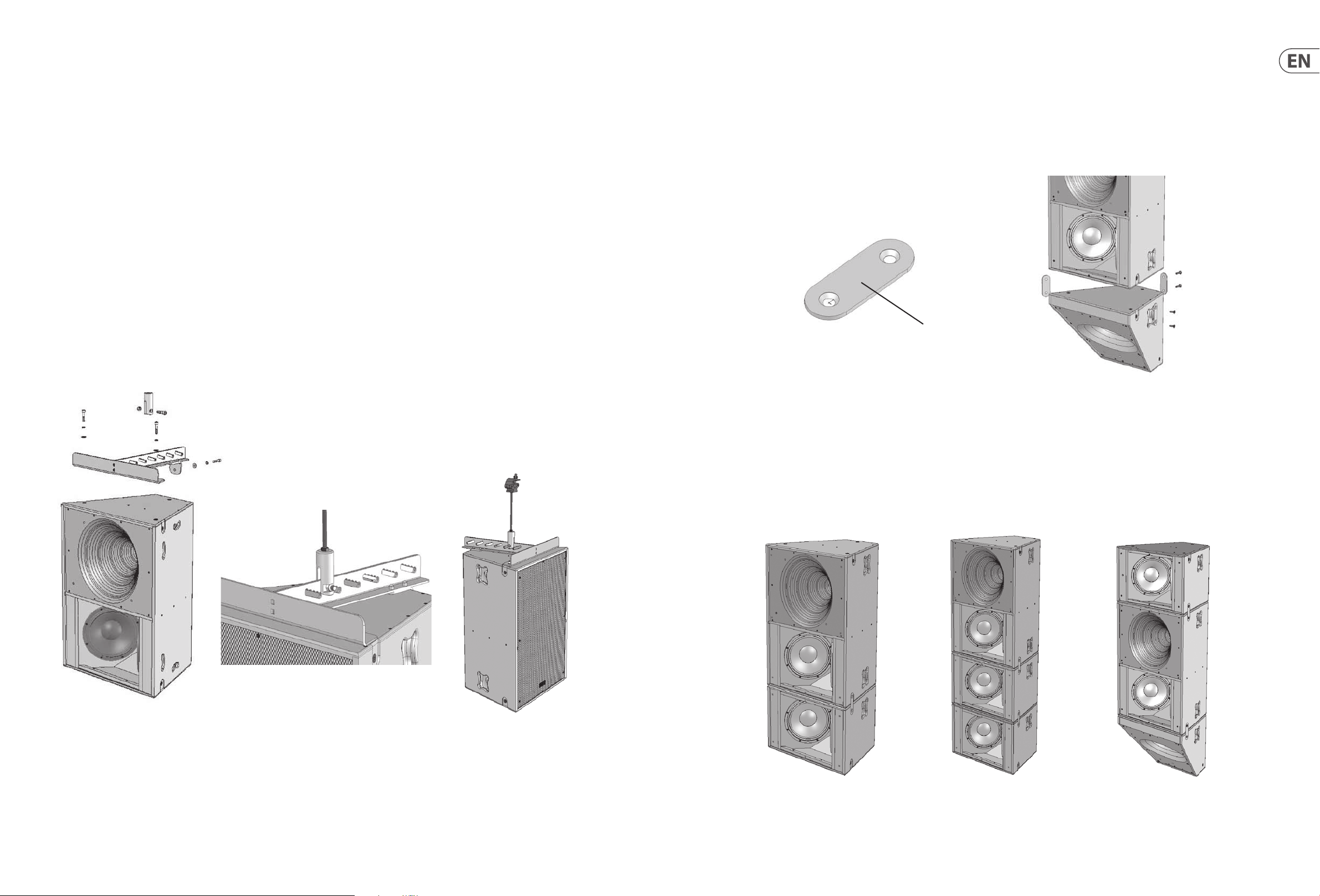
Introduction
The VQ full range products utilize a unique driver technology to radiate a coherent single point source for superior dispersion control when coupled to our single horn.
This advanced design aligns the acoustical centres of the transducers providing a single coherent wavefront emanating from the throat.
The driver uses two concentric annular ring diaphragms. The larger of the two has a 3.5” voice coil and reproduces frequencies from 400 Hz to 7 kHz. Another major
advantage here is that there is no crossover anywhere near the vocal region ensuring the most natural and phase coherent reproduction at this critical area. The 2” HF
diaphragm takes over at 7 kHz to 22 kHz by way of a passive or an active crossover. The external casting features ex tensive heatsinking ensuring good heat transfer for
high power handling and very low power compression.
Connectors/Cabling
Input Connector Panels
Note : The VQ 60 and VQ 100 are congured as standard for Bi-Amp operation.
Tri-Amp operation is possible using the Barrier strip input terminals.
The VQ DF is congured as standard for single amp operation. Bi-Amp operation is possible using the Barrier strip input terminals.
The VQ MB is congured for single amp operation.
VQ 60 / 100 VQ DF
The VQ 60, VQ 100 and VQ DF are tted with 4-pole Neutrik Speakon´ connectors and barrier strip for xed installations.
Speakon Connections -
Speakon has the following advantages over EP and XLR type connectors:
All terminations are solderless; this makes life easier at the time of installation or when eld servicing is required. Contacts will accept 6 sq. mm wire with an outside
diameter of up to 15 mm and a current rating of 30 Amps. The pins of the 2 Speakon sockets identied input/output on the rear of the input panel are paralleled within
the enclosure to facilitate the connection to additional VQ loudspeakers (except the VQ MB). Tannoy has adopted the standard professional audio wiring convention for
the VQ product.
VQ 60 and VQ 100
Speakon Connections
LF Negative (-ve)
LF Positive (+ve)
MF/HF Positive (+ve)
MF/HF Negative (-ve)
VQ DF Speakon
Connections
No connections on pins
1+ and 1-
MF/HF Positive (+ve)
MF/HF Negative (-ve)
VQ MB Speakon
Connections
LF Negative (-ve)
LF Positive (+ve)
No connections on pins
2+ and 2-
Barrier Strip Connections
The barrier strip accommodates bare wire, tinned leads or spade connectors. The barrier strips are specically designed for utilization in xed/permanent
installations. The VQ 60 and VQ 100 are congured for Bi-amp operation; by removing the 4 link wires between the two barrier strips on the termination panel tri-amp
operation is possible. The VQ DF is congured for single amp operation; by removing the 4 link wires between the two barrier strips on the termination panel bi-amp
operation is possible.
VQ MB
VQ 60/100 Bi-amp – Connect LF amplier to LF +/- on top row of barrier strip.
Connect MF/HF amplier to MF/HF +/- on bottom row of barrier strip.
VQ 60/100 Tri-amp – Connect LF amplier to LF +/- on top row of barrier strip.
Connect MF amplier to MF +/- on top row of barrier strip.
Connect HF amplier to HF +/- on top row of barrier strip.
VQ DF Single Amp – Connect MF/HF amplier to MF/HF +/- on bottom row of barrier strip.
VQ DF Bi-amp – Connect MF amplier to MF +/- on top row of barrier strip.
Connect HF amplier to HF +/- on top row of barrier strip.
VQ MB – Connect amplier to LF +/- terminals.
Note that looping out to additional loudspeakers will have the eect of reducing the load on the amplier. Avoid loading ampliers too low. If the amplier is rated for
4 ohms minimum, don't give it a 2 ohm load. Even when the amplier is rated down to 2 ohms remember that in order to keep up with the power the circuit will have
much higher current than before and the wiring will have to handle it. Not only will the wiring losses grow but the damping factor of the system will be degraded. It
might be better to run separate cables from the amp to the speakers or divide the load across two amplier channels.
Cable choice consists mainly of selecting the correct cross sectional area in relation to the cable length and the load impedance. A small cross sec tional area would
increase the cables series resistance, inducing power loss, and response variations (damping factor).
Connectors should be wired with a minimum of 2.5 sq. mm (12 gauge) cable. This will be perfectly satisfactory under normal conditions. In the case of very long cable
runs the wire size should exceed this. The following table shows the change in resistance, sensitivity loss and damping factor due to the eects of cable diameter and
length for two nominal impedance loads (4 ohms & 8 ohms). Use this table to determine a suitable cable diameter for the length of run you require. For resultant
damping factor, values greater than 20 are generally considered adequate for high quality sound reinforcement systems.

14 VQ Series Quick Start Guide 15
Cable Ru n
m ft mm awg ohm
5 16 1.5 m m
10 33 1.5 mm
25 82 1.5 m m
50 164 1.5 m m
100 328 1.5 mm
*The resulting damping factor gures are derived using a good quality professional amplier
Diameter of
conductor
2.5 mm
4 mm
6 mm
2.5 mm
4 mm
6 mm
2.5 mm
4 mm
6 mm
2.5 mm
4 mm
6 mm
2.5 mm
4 mm
6 mm
15
10
6
3
15
10
6
3
15
10
6
3
15
10
6
3
15
10
6
3
Cable
Resistance
0.1 0
0.04
0.01
0.01
0.20
0.07
0.03
0.01
0.49
0.18
0.07
0.03
0.98
0.35
0.14
0.06
1.95
0.70
0.27
0.12
Wire Los s (dB) Damping Factor*
4ohm
Load
0.2
0.1
0
0
0.4
0.2
0.1
0
1
0.4
0.1
0.1
1.9
0.7
0.3
0.1
3.5
1.4
0.6
0.3
8ohm
Load
0.1
0.2
0.1
0.5
0.2
0.1
0.4
0.1
0.1
1.9
0.7
0.3
0.1
VQ Series Recommended Amplier Power
4ohm
Load
40
0
0
0
0
0
0
1
108
255
494
19
55
136
282
8
23
57
123
4
11
29
64
2
6
15
32
✓
✓
✓
✓
✗
✓
✓
✓
✗
✓
✓
✓
✗
✗
✓
✓
✗
✗
✗
✓
8ohm
Load
80
216
510
988
41
111
272
563
16
45
114
246
8
23
58
127
4
11
29
65
✓
✓
✓
✓
✓
✓
✓
✓
✓
✓
✓
✓
✗
✓
✓
✓
✗
✗
✓
✓
Loudspeaker Management Systems
Tannoy VQ series loudspeakers are designed to be used with an electronic signal processor which provides crossover, equalization, delay and dynamic functions.
We strongly recommend LabGruppen PLM+ or D Series with factory presets from LAKE load library. LAKE LM26/44 DSP using the same factory presets from LAKE load
library coupled with LabGruppen C series or FP+ series using models with appropriate output power for the VQ cabinets selected is also recommended. LabGruppen
CAFE software provides a comprehensive solution for selecting the best possible combination of PLM+ or D series products to all Tannoy loudspeaker produc ts,
allowing users to have precise technical data of power delivery, power draw, thermal output, cable infrastructure requirements and BOM calculator. For more
information about LAKE and LabGruppen products, please go to www.lakeprocessing.com or www.labgruppen.com.
VQ60/10 0 Power Requirement
Low Frequency
Passive MF/HF
Mid Frequency
High Frequency
VQ DF
Passive MF/HF
Mid Frequency
High Frequency
VQ MB 2000 W into 4 ohms
2000 W into 4 ohms
400 W into 8 ohms
400 W into 8 ohms
200 W into 8 ohms
400 W into 8 ohms
400 W into 8 ohms
200 W into 8 ohms
Rigging & Suspension
Polarity Checking
It is most important to check the polarity of the wiring before the speaker system is own. A simple method of doing this without a pulse based polarity checker for
LF units is as follows: Connec t two wires to the +ve and -ve terminals of a PP3 battery. Apply the wire which is connected to the +ve terminal of the battery to the
speaker cable leg which you believe to be connected to pin 1+ of the speaker connector and likewise the -ve leg of the battery to pin 1-.
If you have wired it correctly the LF drive unit will move forward, indicating the wiring is correct. All that remains now is to connect the +ve speaker lead to the +ve
terminal on the amplier and the -ve lead to the -ve terminal on the amplier. If however the LF driver moves backwards, the input connections need to be inverted.
There are also commercially available polarity checkers that can be used (IviePAL™, NTI™). If you are commissioning a system using a spec trum analyzer such as
SMAART™, SYSTUNE™, CLIO™, MLSSA™ by checking the impulse response for the rst positive swing. Be sure that EQ and crossover ltering has been removed
before checking.
If problems are encountered, inspect the cable wiring in the rst instance. If you are using ampliers from more than one manufacturer, check the polarity at the
ampliers as well as the loudspeakers.
Amplication & Power Handling
As with all professional loudspeaker systems, the power handling is a function of voice coil thermal capacity. Care should be taken to avoid running the amplier into
clip (clipping is the end result of overdriving any amplier). Damage to the loudspeaker will be sustained if the amplier is driven into clip for any extended period
of time. Headroom of at least 3dB should be allowed. When evaluating an amplier, it is important to take into account its behavior under low impedance load
conditions. A loudspeaker system is highly reactive and with transient signals it can require more current than the nominal impedance would indicate.
Generally a higher power amplier running free of distortion will do less damage to the loudspeaker than a lower power amplier continually clipping. It is also worth
remembering that a high powered amplier running at less than 90% of output power generally sounds a lot better than a lower power amplier running at 100%.
An amplier with insucient drive capability will not allow the full performance or the loudspeaker to be realized.
It is important when using dierent manufacturers ampliers in a single installation that the have very closely matched gains, the variation should be less
than +/- 0.5 dB. This precaution is important to the overall system balance when only a single active crossover is being used with multiple cabinets; it is therefore
recommended that the same ampliers be used throughout.
On the specications pages you will nd the VQ loudspeakers power handling capacity quoted in three categories:-
The VQ hardware covered in this guide has been designed to oer quick, simple, and secure solutions for mounting specic VQ loudspeakers. This hardware has been
designed and manufac tured with a high safety load factor for its specic role. To ensure the safest possible use of the hardware covered in this guide, it must be
assembled in strict accordance with the instructions specied. The information in these manuals relating to the assembly and the safe use of these accessories must be
understood and followed.
The installation of VQ loudspeakers using the dedicated hardware should only ever be carried out by fully qualied installers, in accordance with all the required safety
codes and standards that are applied at the place of installation.
WARNING: As the legal requirements for ying change from country to country, please consult your local safety standards oce before installing any product. We also
recommend that you thoroughly check any laws and bylaws prior to commencing work.
VQ hardware has been designed for use with VQ series loudspeakers only, and is not designed or intended for use with any other Tannoy Commercial products, or any
other devices from other manufacturers. Using Tannoy Professional hardware for any purpose other than that indicated in this guide is considered to be improper use.
Such use can be very dangerous as overloading, modifying; assembling in anyway other than that clearly stated in the manual, or damaging the VQ hardware will
compromise safet y. The component parts of any VQ hardware device must only be assembled using the accessory kits supplied and in strict compliance with the user
manual. The use of other accessories or non-approved methods of assembly may result in an unsafe hardware system by reducing the load safety factor. Welding, or
any other method of permanently xing hardware components together or to the integral xing points in the cabinet should never be used.
Whenever a VQ loudspeaker is xed to a surface using a VQ hardware device, the installer must ensure that the surface is capable of safely and securely supporting the
load. The hardware employed must be safely, securely, and in accordance with the manual, attached both to the loudspeaker and also to the sur face in question, using
only the xing holes provided as standard and covered in the manual. Secure xings to the building structure are vital. Seek help from architects, structural engineers
or other specialists if in any doubt.
All loudspeakers own must, be provided with an independent, correc tly rated and securely attached secondary safety – in addition to the principle hardware device.
This secondary safety must prevent the loudspeaker from dropping more than 150 mm (6") should the principle hardware device fail.
WARNING: Do not under any circumstances use a loudspeaker's handles to support the weight of the loudspeaker except for their intended use: hand carrying.
The handles are not rated to support the load of the loudspeaker for temporar y or permanent installation.
The VQ range of loudspeakers is intended to be suspended or ground-stacked. This section details how to physically congure VQ yware and arrays. The following are
the recommended methods for most situations. Specic situations may require other methods. It is the user's responsibility to determine the viability and safety for
alternate methods and implement them accordingly.
Average (RMS), Programme, & Peak
We recommend using the programme power listed in the loudspeaker specications to choose the correct amplier. To realize the VQ loudspeakers full potential, the
ampliers rated continuous power should be equal to the loudspeakers programme power at its nominal impedance.

16 VQ Series Quick Start Guide 17
Flying a single VQ cabinet in a landscape orientation using EBS forged Eyebolts
Flying A Single VQ Cabinet Using Eyebolts
The simplest method of ying a single VQ cabinet is with a pair of M10 shoulder eyebolts on the top, using a third eyebolt on the rear of the cabinet to tilt the cabinet.
VEB FORGED EYEBOLT
VQ loudspeakers can be own with high quality VEB M10 eyebolts with collar to BS4278:1984. The loudspeakers are equipped
with internal steel braces, which also double as the ying points, and accept VEB M10 eyebolts.
To install the VEB M10 eyebolts remove the original M10 counter sunk screws from the locations you wish to install the VEB M10
eyebolts. Then replace these counter sunk M10 screws with the VEB M10 eyebolts. The M10 insert on the rear of the cabinet also
accepts a VEB M10 eyebolt and should be used for tilting the loudspeaker to the desired angle.
IMPORTANT: It is imperative for safety reasons that a minimum of two eyebolts linked to two independently xed straps are used
per cabinet. Never suspend one enclosure from the other using eyebolts.
Never attempt to use formed eyebolts i.e. formed from a steel rod and bent into an eye.
VQ Flying Bracket (Single Point Hang Flying Bracket)
For safe, exible and simple ying, the VQ Flying bracket is designed to suspend the VQ cabinet from a single pivot point. This allows precise adjustment of aiming
angles with the cabinet in situ. The own VQ loudspeaker must be provided with an independent, correctly rated and securely attached secondary safety – in addition
to the principle hardware device. This secondary safety must prevent the loudspeaker from dropping more than 150mm (6”) should the principle hardware device fail.
Note: All xings should be thread-locked and torqued to 25 Nm.
Item No. Description Quantity
1 M10 Plain Washer 3
2 M10 Spring Washer 3
3 Screw M10 x 50mm 3
4 Bracket Flying - VQ 1
The rod end is used in conjunc tion with the VQ ying bracket. Two types of rod end are available. One is designed to accept ½” UNC threaded rod, and the other accepts
12 mm threaded rod. (Threaded rod supplied by user).
Item No. Description Quantity
1 Rod End – VQ _" UNC or 12mm 3
2 Screw M12x45 Cap Head 3
3 M12 Nyloc Nut 3
18 VQ Series Quick Start Guide 19
Remove the front two countersunk M10 screws located on the top of the cabinet and the top M10 countersunk screw on the top rear of the cabinet. Assemble the
ying bracket as shown. (See g. 1)
IMPORTANT: Only the screws, fasteners, shake proof and plain washers supplied should be used to assemble the VQ ying bracket. Note: All xings should be
thread-locked and torqued to 25 Nm.
When xed in position the rod end can be moved along any of the ve serrated edges within each slot to ne tune the loudspeakers tilt angle. (See g. 2) Threaded
rod used should be no more than 300 mm (12") in length. The user is responsible for supplying the correct threaded rod. The minimum specications for the
threaded rod are:-
USA - Grade B7 (1438 lbs, 650 kgs for ½" rod based on a safety factor of 10:1)
Metric - Grade 10.9 (1459 lbs, 660 kgs for 12 mm rod based on a safety factor 10:1)
Use the appropriate nuts to lock the rod end to the threaded rod (supplied by user). Use a Nyloc nut at the top of the threaded rod to secure the pole clamp
(supplied by user).
The threaded rod can be attached to a suitably rated Uni-Strut accessor y.
Always use Nyloc nuts to secure the threaded rod to the pole clamp or Uni-Strut.
The rigging of a own sound system may be dangerous unless undertaken by qualied personnel with the required experience and certication to perform the
necessary tasks.
Fixing of hanging points in a roof should always be carried out by a professional rigger and in accordance with the local rules of the venue.
A maximum of VQ 60 + VQ MB + VQ DF (350 lbs, 160 kg) can be own from a single threaded rod. This combination carries a safety factor of 8:1. (See g. 3)
VQ Link Plate
The VQ link plate is used to join a VQ DF or VQ MB to a VQ 60 or VQ 100 cabinet. Three link plates are used to connect each cabinet. The Link plates are supplied as
standard with each VQ DF and VQ MB.
Remove the M10 countersunk screws as shown in the diagram opposite. Use the same screws to x the link plate in place. The link plate will sit ush in the cabinet
indentations. Two longer M10 bolts are supplied with the link plates. These bolts should be used to x the rear link plate in position.
Note: All xings should be thread-locked and torqued to 25 Nm
LINK PLATE
(g. 1)
(g. 2)
(g. 3)
Using The VQ MB For Additional Pattern Control
The VQ link plate is used to join a VQ DF or VQ MB to a VQ 60 or VQ 100 cabinet. Three link plates are used to connect each cabinet. The Link plates are supplied as
standard with each VQ DF and VQ MB.
Remove the M10 countersunk screws as shown in the diagram opposite. Use the same screws to x the link plate in place. The link plate will sit ush in the cabinet
indentations. Two longer M10 bolts are supplied with the link plates. These bolts should be used to x the rear link plate in position.

20 VQ Series Quick Start Guide 21
Arraying VQ 60
A single VQ 100 can produce more power and clarity over its 100 degree beamwidth area than many arrayed solutions using multiple cabinets, a great advantage when
considering your building aesthetics. A VQ 100 is not designed to be arrayed.
Two VQ 60s can be arrayed to produce a well dened horizontal coverage angle of 120 degrees.
The VQ array plate is designed to optimally array two VQ 60 cabinets. To t the plate, set the boxes on the ground with the rear edge of the cabinets touching. Remove
the two M10 countersunk bolts and replace with either the M10 screw or the supplied eyebolts. Locate the four M10 eyebolts from the xings kit supplied and insert
these through the array plate into the rigging points in the cabinet. These will be used to pick up the array.Repeat the same procedure at the bottom of the cabinets,
use the M10 screw. If ying in a landscape orientation the M10 screw can be used on both array plates.
Note: All xings should be thread-locked and torqued to 25 Nm
Two independent pick-up points are recommended for suspending the array. The main pickup points are the two rear eyebolts. The two front eyebolts may be
used as safety points.
Item No. Description Quantity
1 M10 Plain Washer 8
2 M10 Spring Washer 8
3 Screw M10 x 50 mm 8
4 Eyebolt M10 4
5 Array Bracket 2
Introducción
Los productos de gama completa VQ utilizan una tecnología de controlador única para irradiar una fuente de un solo punto coherente para un control de dispersión
superior cuando se acopla a nuestra bocina única. Este diseño avanzado alinea los centros acústicos de los transductores proporcionando un único frente de onda
coherente que emana de la garganta.
El conductor utiliza dos diafragmas de anillo anular concéntricos. El más grande de los dos tiene una bobina móvil de 3,5” y reproduce frecuencias de 400 Hz a 7 kHz.
Otra ventaja importante aquí es que no hay ningún cruce cerca de la región vocal, lo que garantiza la reproducción más natural y coherente de fase en esta área crítica.
El diafragma HF de 2” toma el control de 7 kHz a 22 kHz mediante un crossover pasivo o activo. La fundición externa cuenta con un amplio disipador de calor que
garantiza una buena transferencia de calor para un manejo de alta potencia y una compresión de muy baja potencia.
Conectores/cableado
Paneles de conectores de entrada
Nota: VQ 60 y VQ 100 están congurados como estándar para operación Bi-Amp.
La operación Tri-Amp es posible usando los terminales de entrada de la regleta de barrera.
El VQ DF está congurado como estándar para operación de un solo amplicador. La operación Bi-Amp es posible usando los terminales de entrada de la tira de barrera.
El VQ MB está congurado para funcionar con un solo amplicador.
VQ 60 / 100 VQ DF
VQ MB
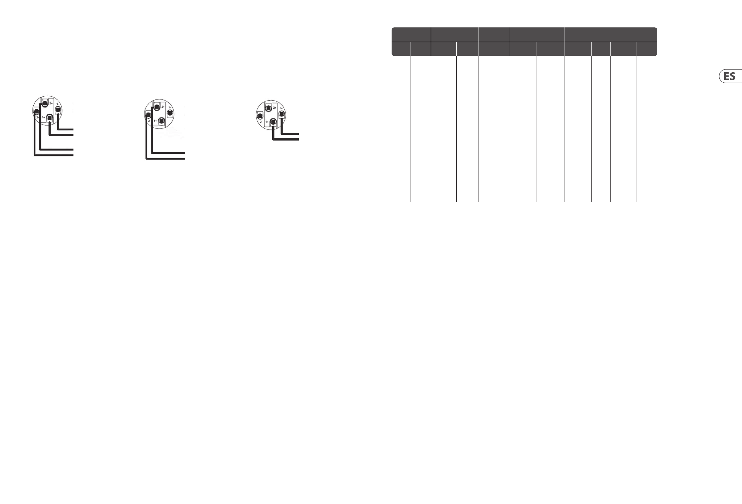
22 VQ Series Quick Start Guide 23
Los VQ 60, VQ 100 y VQ DF están equipados con conectores Neutrik Speakon´ de 4 polos y regleta de barrera para instalaciones jas.
Conexiones Speakon -
Speakon tiene las siguientes ventajas sobre los conectores de tipo EP y XLR:
Todas las terminaciones no tienen soldadura; esto hace la vida más fácil en el momento de la instalación o cuando se requiere servicio de campo. Los contactos
aceptarán cables de 6 mm cuadrados con un diámetro exterior de hasta 15 mm y una corriente nominal de 30 amperios. Los pines de los 2 enchufes Speakon
identicados como entrada/salida en la parte posterior del panel de entrada están en paralelo dentro del gabinete para facilitar la conexión a altavoces VQ adicionales
(excepto el VQ MB). Tannoy ha adoptado la convención de cableado de audio profesional estándar para el producto VQ.
VQ 60 and VQ 100
Speakon Connections
LF Negative (-ve)
LF Positive (+ve)
MF/HF Positive (+ve)
MF/HF Negative (-ve)
VQ DF Speakon
Connections
No connections on pins
1+ and 1-
MF/HF Positive (+ve)
MF/HF Negative (-ve)
VQ MB Speakon
Connections
LF Negative (-ve)
LF Positive (+ve)
No connections on pins
2+ and 2-
Conexiones de bandas de barrera
La tira de barrera admite cables desnudos, cables estañados o conectores de pala. Las tiras de barrera están diseñadas especícamente para su uso en instalaciones
jas/permanentes. El VQ 60 y VQ 100 están congurados para operación Bi-amp; Al quitar los 4 cables de enlace entre las dos tiras de barrera en el panel de
terminación, es posible la operación de tres amperios. El VQ DF está congurado para funcionar con un solo amplicador; Al quitar los 4 cables de enlace entre las dos
tiras de barrera en el panel de terminación, es posible la operación de biamplicación.
Ejecución de cable
metro pie mm awg ohm
5 dieciséis 1,5 mm
10 33 1,5 mm
25 82 1,5 mm
50 164 1,5 mm
100 328 1,5 mm
* Las cifras del factor de amortiguación resultantes se obtienen utilizando un amplicador profesional de buena calidad
Diametro de
conductor
2,5 mm
4 mm
6 mm
2,5 mm
4 mm
6 mm
2,5 mm
4 mm
6 mm
2,5 mm
4 mm
6 mm
2,5 mm
4 mm
6 mm
15
10
6
3
15
10
6
3
15
10
6
3
15
10
6
3
15
10
6
3
Cable
Resistencia
0,10
0,04
0,01
0,01
0,20
0,07
0,03
0,01
0,49
0,18
0,07
0,03
0,98
0,35
0,14
0,06
1,95
0,70
0,27
0,12
Pérdida d e cable (dB) Factor de amortiguamiento*
4 ohmios
Carga
0,2
0,1
0
0
0.4
0,2
0,1
0
1
0.4
0,1
0,1
1,9
0,7
0,3
0,1
3,5
1.4
0,6
0,3
8 ohmios
Carga
0,1
0
0
0
0,2
0,1
0
0
0,5
0,2
0,1
0
1
0.4
0,1
0,1
1,9
0,7
0,3
0,1
4 ohmios
Carga
40
108
255
494
19
55
136
282
8
23
57
123
4
11
29
64
2
6
15
32
8 ohmios
Carga
✓
✓
✓
✓
✗
✓
✓
✓
✗
✓
✓
✓
✗
✗
✓
✓
✗
✗
✗
✓
80
216
510
988
41
111
272
563
dieciséis
45
114
246
8
23
58
127
4
11
29
sesenta y
cinco
✓
✓
✓
✓
✓
✓
✓
✓
✓
✓
✓
✓
✗
✓
✓
✓
✗
✗
✓
✓
VQ 60/100 Bi-amp – Conecte el amplicador LF a LF +/- en la la superior de la tira de barrera.
Conecte el amplicador MF/HF a MF/HF +/- en la la inferior de la tira de barrera.
VQ 60/100 Tri-amp – Conecte el amplicador LF a LF +/- en la la superior de la tira de barrera.
Conecte el amplicador MF a MF +/- en la la superior de la tira de barrera.
Conecte el amplicador de HF a HF +/- en la la superior de la tira de barrera.
Amplicador único VQ DF – Conecte el amplicador MF/HF a MF/HF +/- en la la inferior de la tira de barrera.
VQ DF Biamplicador – Conecte el amplicador MF a MF +/- en la la superior de la tira de barrera.
Conecte el amplicador de HF a HF +/- en la la superior de la tira de barrera.
VQ MB – Conecte el amplicador a los terminales LF +/-.
Tenga en cuenta que la conexión en bucle a altavoces adicionales tendrá el efecto de reducir la carga en el amplicador. Evite cargar amplicadores demasiado
bajos. Si el amplicador está clasicado para un mínimo de 4 ohmios, no le dé una carga de 2 ohmios. Incluso cuando el amplicador tiene una potencia nominal de
2 ohmios, recuerde que para mantenerse al día con la potencia, el circuito tendrá una corriente mucho más alta que antes y el cableado tendrá que soportarlo. No
solo aumentarán las pérdidas de cableado, sino que también se degradará el factor de amortiguación del sistema. Puede que sea mejor instalar cables separados del
amplicador a los altavoces o dividir la carga en dos canales del amplicador.
La elección del cable consiste principalmente en seleccionar el área de sección transversal correcta en relación con la longitud del cable y la impedancia de carga.
Un área de sección transversal pequeña aumentaría la resistencia en serie de los cables, induciendo pérdida de potencia y variaciones de respuesta (factor de
amortiguación).
Los conectores deben cablearse con un cable mínimo de 2,5 mm2 (calibre 12). Esto será perfectamente satisfactorio en condiciones normales. En el caso de tramos de
cable muy largos, el tamaño del cable debe exceder este. La siguiente tabla muestra el cambio en la resistencia, la pérdida de sensibilidad y el factor de amortiguación
debido a los efectos del diámetro y la longitud del cable para dos cargas de impedancia nominal (4 ohmios y 8 ohmios). Utilice esta tabla para determinar un diámetro
de cable adecuado para la longitud del tramo que necesita. Para el fac tor de amortiguación resultante, los valores superiores a 20 generalmente se consideran
adecuados para sistemas de refuerzo de sonido de alta calidad.
Comprobación de polaridad
Es muy importante comprobar la polaridad del cableado antes de que el sistema de altavoces se vuele. Un método simple para hacer esto sin un vericador de
polaridad basado en pulsos para unidades LF es el siguiente: Conecte dos cables a los terminales + ve y -ve de una batería PP3. Aplique el cable que está conectado al
terminal + ve de la batería a la pata del cable del altavoz que cree que está conectado al pin 1+ del conector del altavoz y también la pata -ve de la batería al pin 1-.
Si lo ha cableado correctamente, la unidad de transmisión LF avanzará, lo que indica que el cableado es correcto. Todo lo que queda ahora es conectar el cable del
altavoz + ve al terminal + ve del amplicador y el cable -ve al terminal -ve del amplicador. Sin embargo, si el controlador LF se mueve hacia atrás, las conexiones de
entrada deben invertirse.
También hay comprobadores de polaridad disponibles comercialmente que se pueden utilizar (IviePAL™, NTI™). Si está poniendo en servicio un sistema utilizando
un analizador de espectro como SMAART™, SYSTUNE™, CLIO™, MLSSA™, verique la respuesta de impulso para el primer cambio positivo. Asegúrese de que se haya
eliminado el EQ y el ltro de cruce antes de realizar la comprobación.
Si se encuentran problemas, inspeccione el cableado del cable en primera instancia. Si está utilizando amplicadores de más de un fabricante, compruebe la polaridad
en los amplicadores y en los altavoces.
Amplicación y manejo de potencia
Como ocurre con todos los sistemas de altavoces profesionales, el manejo de potencia es una función de la capacidad térmica de la bobina móvil. Se debe tener cuidado
para evitar ejecutar el amplicador en un clip (el recorte es el resultado nal de saturar cualquier amplicador). El daño al altavoz se mantendrá si el amplicador se
coloca en el clip durante un período prolongado de tiempo. Se debe permitir un espacio para la cabeza de al menos 3dB. Al evaluar un amplicador, es importante
tener en cuenta su comportamiento en condiciones de carga de baja impedancia. Un sistema de altavoces es altamente reactivo y con señales transitorias puede
requerir más corriente de la que indicaría la impedancia nominal.
Por lo general, un amplicador de potencia superior que funcione sin distorsión dañará menos el altavoz que un amplicador de potencia inferior que se recorta
continuamente. También vale la pena recordar que un amplicador de alta potencia que funciona a menos del 90% de la potencia de salida generalmente suena
mucho mejor que un amplicador de menor potencia que funciona al 100%. Un amplicador con capacidad de excitación insuciente no permitirá que se obtenga el
rendimiento completo o el altavoz.
Cuando se utilizan amplicadores de diferentes fabricantes en una sola instalación, es importante que tengan ganancias muy parecidas; la variación debe ser inferior
a +/- 0,5 dB. Esta precaución es importante para el equilibrio general del sistema cuando solo se utiliza un único crossover activo con varios gabinetes; por lo tanto, se
recomienda utilizar los mismos amplicadores en todas partes.
En las páginas de especicaciones, encontrará la capacidad de manejo de potencia de los altavoces VQ en tres categorías:
Promedio (RMS), programa y pico
Recomendamos utilizar la potencia del programa que se indica en las especicaciones de los altavoces para elegir el amplicador correcto. Para realizar el potencial
completo de los altavoces VQ, la potencia nominal continua de los amplicadores debe ser igual a la potencia del programa de los altavoces en su impedancia nominal.
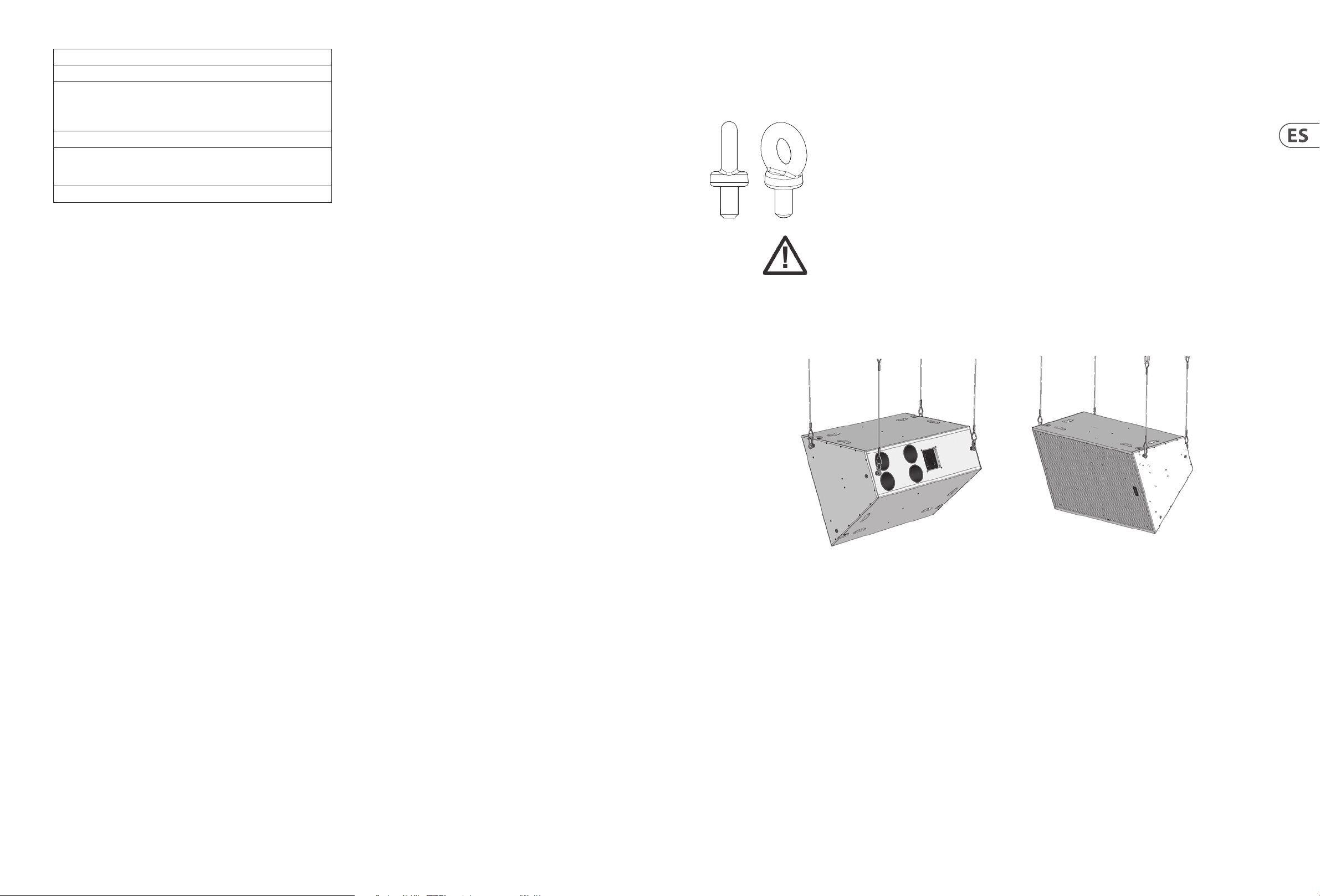
24 VQ Series Quick Start Guide 25
Flying a single VQ cabinet in a landscape orientation using EBS forged Eyebolts
Potencia de amplicador recomendada de la serie VQ
VQ60/10 0 Requisitos de energía
Baja frecuencia
MF/HF pasivo
Frecuencia media
Alta frecuencia
VQ DF
MF/HF pasivo
Frecuencia media
Alta frecuencia
VQ MB 2000 W en 4 ohmios
2000 W en 4 ohmios
400 W en 8 ohmios
400 W en 8 ohmios
200 W en 8 ohmios
400 W en 8 ohmios
400 W en 8 ohmios
200 W en 8 ohmios
Sistemas de gestión de altavoces
Los altavoces de la serie Tannoy VQ están diseñados para ser utilizados con un procesador de señal electrónico que proporciona funciones de cruce, ecualización,
retardo y dinámicas. Recomendamos encarecidamente LabGruppen PLM + o D Series con ajustes preestablecidos de fábrica de la biblioteca de carga LAKE. También
se recomienda el DSP LAKE LM26/44 utilizando los mismos ajustes preestablecidos de fábrica de la biblioteca de carga LAKE junto con la serie LabGruppen C o la serie
FP + utilizando modelos con la potencia de salida adecuada para los gabinetes VQ seleccionados. El software LabGruppen CAFE proporciona una solución integral
para seleccionar la mejor combinación posible de productos de la serie PLM + o D para todos los productos de altavoces Tannoy, lo que permite a los usuarios tener
datos técnicos precisos de suministro de energía, consumo de energía, salida térmica, requisitos de infraestructura de cables y calculadora de lista de materiales. Para
obtener más información sobre los productos LAKE y LabGruppen, visite www.
Volar un solo gabinete VQ con cáncamos
El método más simple de volar un solo gabinete VQ es con un par de cáncamos de hombro M10 en la parte superior, usando un tercer cáncamo en la parte posterior del
gabinete para inclinar el gabinete.
TORNILLO FORJADO VEB
Los altavoces VQ se pueden colgar con cáncamos VEB M10 de alta calidad con collar según BS4278: 1984. Los altavoces están
equipados con tirantes de acero internos, que también funcionan como puntos de vuelo, y aceptan cáncamos VEB M10.
Para instalar los cáncamos VEB M10, retire los tornillos avellanados M10 originales de las ubicaciones donde desea instalar los
cáncamos VEB M10. Luego reemplace estos tornillos M10 avellanados con los cáncamos VEB M10. El inserto M10 en la parte
posterior del gabinete también acepta un cáncamo VEB M10 y debe usarse para inclinar el altavoz al ángulo deseado.
IMPORTANTE: Es imperativo por razones de seguridad que se use un mínimo de dos cáncamos unidos a dos correas jadas
independientemente por gabinete. Nunca suspenda un gabinete del otro usando pernos de argolla.
Nunca intente utilizar cáncamos formados, es decir, formados a partir de una varilla de acero y doblados en un ojo.
Volar un solo gabinete VQ en orientación horizontal con cáncamos forjados de EBS
Aparejo y suspensión
El hardware VQ cubierto en esta guía ha sido diseñado para ofrecer soluciones rápidas, simples y seguras para el montaje de altavoces VQ especícos. Este hardware ha
sido diseñado y fabricado con un factor de carga de seguridad alto para su función especíca. Para garantizar el uso más seguro posible del hardware cubierto en esta
guía, debe ensamblarse estrictamente de acuerdo con las instrucciones especicadas. La información contenida en estos manuales relacionada con el montaje y el uso
seguro de estos accesorios debe entenderse y seguirse.
La instalación de los altavoces VQ utilizando el hardware dedicado solo debe ser realizada por instaladores totalmente calicados, de acuerdo con todos los códigos y
normas de seguridad requeridos que se aplican en el lugar de instalación.
ADVERTENCIA: Dado que los requisitos legales para volar cambian de un país a otro, consulte con la ocina de normas de seguridad local antes de instalar cualquier
producto. También le recomendamos que compruebe minuciosamente las leyes y los estatutos antes de comenzar a trabajar.
El hardware VQ ha sido diseñado para su uso únicamente con altavoces de la serie VQ, y no está diseñado ni previsto para su uso con ningún otro produc to comercial
de Tannoy ni con ningún otro dispositivo de otros fabricantes. El uso de hardware Tannoy Professional para cualquier propósito distinto al indicado en esta guía se
considera un uso inadecuado. Tal uso puede ser muy peligroso como sobrecargar, modicar; El montaje de cualquier otra forma que no sea la claramente establecida
en el manual o el daño del hardware VQ comprometerá la seguridad. Los componentes de cualquier dispositivo de hardware VQ solo deben ensamblarse utilizando los
kits de accesorios suministrados y en estricto cumplimiento del manual del usuario. El uso de otros accesorios o métodos de montaje no aprobados puede resultar en
un sistema de hardware inseguro al reducir el fac tor de seguridad de la carga. Soldadura,
Siempre que un altavoz VQ se je a una supercie utilizando un dispositivo de hardware VQ, el instalador debe asegurarse de que la supercie sea capaz de soportar
la carga de forma segura. Los herrajes empleados deben estar sujetos de forma segura, segura y de acuerdo con el manual, tanto al altavoz como a la supercie en
cuestión, utilizando únicamente los oricios de jación proporcionados de serie y cubiertos en el manual. Las jaciones seguras a la estructura del edicio son vitales.
Busque la ayuda de arquitectos, ingenieros estructurales u otros especialistas si tiene alguna duda.
Todos los altavoces volados deben estar provistos de un dispositivo de seguridad secundario independiente, clasicado correc tamente y conectado de forma
segura, además del dispositivo de hardware principal. Esta seguridad secundaria debe evitar que el altavoz caiga más de 150 mm (6 “) si falla el dispositivo de
hardware principal.
ADVERTENCIA: No utilice bajo ninguna circunstancia las asas de un altavoz para soportar el peso del altavoz, excepto para su uso previsto: transporte manual. Las asas
no están clasicadas para soportar la carga del altavoz para una instalación temporal o permanente.
La gama de altavoces VQ está diseñada para ser suspendida o apilada en el suelo. Esta sección detalla cómo congurar físicamente los arreglos y el yware de VQ. Los
siguientes son los métodos recomendados para la mayoría de situaciones. Las situaciones especícas pueden requerir otros métodos. Es responsabilidad del usuario
determinar la viabilidad y seguridad de métodos alternativos e implementarlos en consecuencia.
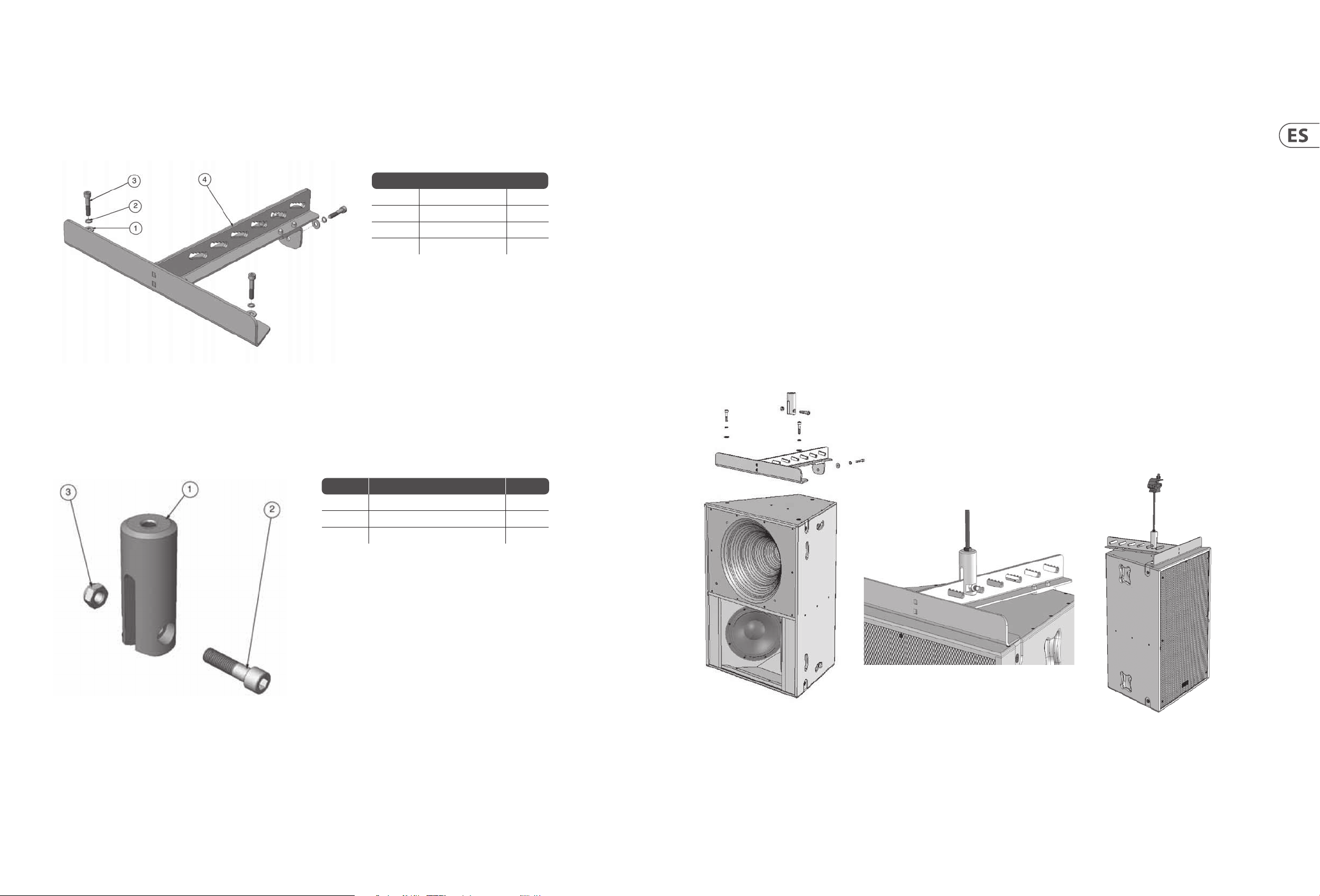
26 VQ Series Quick Start Guide 27
Soporte de vuelo VQ (soporte de vuelo colgante de un solo punto)
Para un vuelo seguro, exible y simple, el soporte de vuelo VQ está diseñado para suspender el gabinete VQ de un solo punto de pivote. Esto permite un ajuste preciso
de los ángulos de orientación con el gabinete in situ. El altavoz VQ colgado debe estar provisto de un dispositivo de seguridad secundario independiente, clasicado
correctamente y rmemente conectado, además del dispositivo de hardware principal. Esta seguridad secundaria debe evitar que el altavoz caiga más de 150 mm (6")
si falla el dispositivo de hardware principal.
Nota: Todas las jaciones deben bloquearse con rosca y apretarse a un par de 25 Nm.
Artículo No. Descripción Cantidad
1 Arandela plana M10 3
2 Arandela de resorte M10 3
3 Tornillo M10 x 50 mm 3
4 Sop orte volador - VQ 1
Quite los dos tornillos avellanados M10 frontales ubicados en la parte superior del gabinete y el tornillo avellanado M10 superior en la parte superior trasera del
gabinete. Monte el soporte volante como se muestra. (Ver g.1)
IMPORTANTE: Solo los tornillos, sujetadores, arandelas a prueba de sacudidas y arandelas planas suministrados deben usarse para ensamblar el soporte volante VQ.
Nota: Todas las jaciones deben bloquearse con rosca y apretarse a un par de 25 Nm.
Cuando se ja en su posición, el extremo de la varilla se puede mover a lo largo de cualquiera de los cinco bordes dentados dentro de cada ranura para ajustar el ángulo
de inclinación de los altavoces. (Ver g. 2) La varilla roscada utilizada no debe tener más de 300 mm (12") de longitud. El usuario es responsable de suministrar la
varilla roscada correcta. Las especicaciones mínimas para la varilla roscada son: -
EE. UU. - Grado B7 (1438 lbs, 650 kgs para varilla de ½ “según un factor de seguridad de 10: 1)
Métrico - Grado 10.9 (1459 lbs, 660 kgs para varilla de 12 mm basado en un factor de seguridad de 10: 1)
Utilice las tuercas adecuadas para bloquear el ex tremo de la varilla a la varilla roscada (suministrada por el usuario). Use una tuerca Nyloc en la parte superior de la
varilla roscada para asegurar la abrazadera del poste (suministrada por el usuario).
La varilla roscada se puede unir a un accesorio Uni-Strut con la clasicación adecuada.
Utilice siempre tuercas Nyloc para asegurar la varilla roscada a la abrazadera del poste o Uni-Strut.
El aparejo de un sistema de sonido volado puede ser peligroso a menos que sea realizado por personal calicado con la experiencia y certicación necesarias para
realizar las tareas necesarias.
La jación de puntos de suspensión en un techo siempre debe ser realizada por un aparejador profesional y de acuerdo con las reglas locales del lugar.
Se puede volar un máximo de VQ 60 + VQ MB + VQ DF (350 lbs, 160 kg) desde una sola varilla roscada. Esta combinación tiene un factor de seguridad de 8: 1. (Ver g.3)
El extremo de la varilla se utiliza junto con el soporte volante VQ. Hay dos tipos de ex tremos de varilla disponibles. Uno está diseñado para aceptar varilla roscada UNC
de ½" y el otro acepta varilla roscada de 12 mm. (Varilla roscada suministrada por el usuario).
Artículo No. Descripción Cantidad
1 Ex tremo de varilla - VQ _ “UNC o 12 mm 3
2 Tornillo M12x45 Cabeza de tapa 3
3 Tuerca Nyloc M12 3
(g. 1)
(g. 3)
(g. 2)

28 VQ Series Quick Start Guide 29
Placa de enlace VQ
La placa de enlace VQ se utiliza para unir un VQ DF o VQ MB a un gabinete VQ 60 o VQ 100. Se utilizan tres placas de enlace para conec tar cada armario. Las placas Link
se suministran de serie con cada VQ DF y VQ MB.
Quite los tornillos avellanados M10 como se muestra en el diagrama al lado. Utilice los mismos tornillos para jar la placa de enlace en su lugar. La placa de enlace se
asentará al ras en las muescas del gabinete. Se suministran dos pernos M10 más largos con las placas de unión. Estos pernos deben usarse para jar la placa del brazo
trasero en su posición.
Nota: Todas las jaciones deben estar bloqueadas con rosca y apretadas a 25 Nm.
LINK PLATE
Arreglo de VQ 60
Un solo VQ 100 puede producir más potencia y claridad en su área de ancho de haz de 100 grados que muchas soluciones en matriz que utilizan múltiples gabinetes,
una gran ventaja al considerar la estética de su edicio. Un VQ 100 no está diseñado para arreglos.
Se pueden colocar dos VQ 60 para producir un ángulo de cobertura horizontal bien denido de 120 grados.
La placa de matriz VQ está diseñada para organizar de manera óptima dos gabinetes VQ 60. Para colocar la placa, coloque las cajas en el suelo con el borde trasero de
los armarios tocando. Retire los dos pernos avellanados M10 y reemplácelos con el tornillo M10 o los pernos de argolla suministrados. Localice los cuatro cáncamos
M10 del kit de jaciones suministrado e insértelos a través de la placa de matriz en los puntos de sujeción del gabinete. Estos se usarán para recoger la matriz.
Repita el mismo procedimiento en la parte inferior de los gabinetes, use el tornillo M10. Si vuela en orientación horizontal, el tornillo M10 se puede utilizar en ambas
placas de matriz.
Nota: Todas las jaciones deben estar bloqueadas con rosca y apretadas a 25 Nm.
Se recomiendan dos puntos de recogida independientes para suspender la matriz. Los principales puntos de recogida son los dos cáncamos traseros. Los dos cáncamos
delanteros se pueden utilizar como puntos de seguridad.
Artículo No. Descripción Cantidad
1 Arandela plana M10 8
2 Arandela de resorte M10 8
3 Tornillo M10 x 50 mm 8
4 Cáncamo M10 4
5 Soporte de matriz 2
Uso del VQ MB para un control de patrones adicional
La placa de enlace VQ se utiliza para unir un VQ DF o VQ MB a un gabinete VQ 60 o VQ 100. Se utilizan tres placas de enlace para conec tar cada armario. Las placas Link
se suministran de serie con cada VQ DF y VQ MB.
Quite los tornillos avellanados M10 como se muestra en el diagrama al lado. Utilice los mismos tornillos para jar la placa de enlace en su lugar. La placa de enlace se
asentará al ras en las muescas del gabinete. Se suministran dos pernos M10 más largos con las placas de unión. Estos pernos deben usarse para jar la placa del brazo
trasero en su posición.

30 VQ Series Quick Start Guide 31
Introduction
Les produits de la gamme complète VQ utilisent une technologie de haut-parleur unique pour rayonner une source de point unique cohérente pour un contrôle
supérieur de la dispersion lorsqu’ils sont couplés à notre cornet unique. Cette conception avancée aligne les centres acoustiques des transduc teurs en fournissant un
seul front d’onde cohérent émanant de la gorge.
Le conducteur utilise deux diaphragmes annulaires concentriques. Le plus grand des deux a une bobine acoustique de 3,5 pouces et reproduit les fréquences de 400 Hz
à 7 kHz. Un autre avantage majeur ici est qu’il n’y a pas de croisement à proximité de la région vocale assurant la reproduc tion la plus naturelle et la plus cohérente
en phase dans cette zone critique. Le diaphragme HF 2 ”prend le relais de 7 kHz à 22 kHz via un ltre passif ou actif. Le moulage externe présente une dissipation
thermique étendue assurant un bon transfert de chaleur pour une gestion de puissance élevée et une compression de puissance très faible.
Connecteurs/Câblage
Panneaux de connecteurs d’entrée
Remarque: Les VQ 60 et VQ 100 sont congurés en standard pour un fonctionnement bi-amplicateur.
Le fonctionnement Tri-Amp est possible en utilisant les bornes d’entrée de la barrette barrière.
Le VQ DF est conguré en standard pour un fonctionnement à un seul ampli. Le fonctionnement bi-amp est possible à l’aide des bornes d’entrée de la
barrette de protection.
Le VQ MB est conguré pour un fonctionnement à un seul ampli.
VQ 60 / 100 VQ DF
Les VQ 60, VQ 100 et VQ DF sont équipés de connecteurs Neutrik Speakon à 4 pôles et d’une bande de barrière pour les installations xes.
Connexions Speakon -
Speakon présente les avantages suivants par rapport aux connecteurs de type EP et XLR:
Toutes les terminaisons sont sans soudure; cela facilite la vie au moment de l’installation ou lorsqu’un entretien sur site est nécessaire. Les contac ts acceptent un l de
6 mm2 avec un diamètre extérieur jusqu’à 15 mm et un courant nominal de 30 ampères. Les broches des 2 prises Speakon identiées en entrée/sortie à l’arrière du
panneau d’entrée sont mises en parallèle dans le boîtier pour faciliter la connexion à des haut-parleurs VQ supplémentaires (à l’exception du VQ MB). Tannoy a adopté
la convention de câblage audio professionnelle standard pour le produit VQ.
VQ 60 and VQ 100
Speakon Connections
LF Negative (-ve)
LF Positive (+ve)
MF/HF Positive (+ve)
MF/HF Negative (-ve)
VQ DF Speakon
Connections
No connections on pins
1+ and 1-
MF/HF Positive (+ve)
MF/HF Negative (-ve)
VQ MB Speakon
Connections
LF Negative (-ve)
LF Positive (+ve)
No connections on pins
2+ and 2-
Connexions de la bande de barrière
La bande de barrière accueille des ls nus, des ls étamés ou des connecteurs à fourche. Les bandes de barrière sont spéciquement conçues pour une utilisation dans
des installations xes/permanentes. Les VQ 60 et VQ 100 sont congurés pour un fonctionnement bi-ampli; en retirant les 4 ls de liaison entre les deux bandes de
barrière sur le panneau de terminaison, un fonctionnement tri-ampères est possible. Le VQ DF est conguré pour un fonctionnement à un seul ampli; en retirant les 4
ls de liaison entre les deux bandes de barrière sur le panneau de terminaison, un fonc tionnement bi-ampère est possible.
VQ MB
VQ 60/100 Bi-ampli - Connectez l’amplicateur LF à LF +/- sur la rangée supérieure de la bande de barrière.
Connectez l’amplicateur MF/HF à MF/HF +/- sur la rangée inférieure de la bande de barrière.
VQ 60/100 Tri-amp - Connectez l’amplicateur LF à LF +/- sur la rangée supérieure de la bande de barrière.
Connectez l’amplicateur MF à MF +/- sur la rangée supérieure de la bande de barrière.
Connectez l’amplicateur HF à HF +/- sur la rangée supérieure de la bande de barrière.
Amplicateur unique VQ DF - Connectez l’amplicateur MF/HF à MF/HF +/- sur la rangée inférieure de la bande de barrière.
VQ DF Bi-ampli - Connectez l’amplicateur MF à MF +/- sur la rangée supérieure de la bande de barrière.
Connectez l’amplicateur HF à HF +/- sur la rangée supérieure de la bande de barrière.
VQ MB - Connec tez l’amplicateur aux bornes LF +/-.
Notez que le bouclage vers des haut-parleurs supplémentaires aura pour eet de réduire la charge sur l’amplicateur. Évitez de charger les amplicateurs trop bas.
Si l’amplicateur est évalué pour 4 ohms minimum, ne lui donnez pas une charge de 2 ohms. Même lorsque l’amplicateur est évalué à 2 ohms, rappelez-vous que
pour rester à la hauteur de la puissance, le circuit aura un courant beaucoup plus élevé qu’auparavant et le câblage devra le gérer. Non seulement les pertes de câblage
augmenteront, mais le facteur d’amortissement du système sera dégradé. Il peut être préférable de faire passer des câbles séparés de l’ampli aux haut-parleurs ou de
diviser la charge sur deux canaux d’amplication.
Le choix du câble consiste principalement à sélectionner la bonne section transversale en fonction de la longueur du câble et de l’impédance de charge. Une petite
section transversale augmenterait la résistance série des câbles, induisant une perte de puissance et des variations de réponse (facteur d’amortissement).
Les connecteurs doivent être câblés avec un câble d’au moins 2,5 mm2 (calibre 12). Cela sera parfaitement satisfaisant dans des conditions normales. Dans le
cas de très longs câbles, la taille du l doit dépasser cette valeur. Le tableau suivant montre l’évolution de la résistance, de la perte de sensibilité et du facteur
d’amortissement en raison des eets du diamètre et de la longueur du câble pour deux charges d’impédance nominale (4 ohms et 8 ohms). Utilisez ce tableau pour
déterminer un diamètre de câble adapté à la longueur de câble dont vous avez besoin. Pour le facteur d’amortissement résultant, des valeurs supérieures à 20 sont
généralement considérées comme adéquates pour les systèmes de sonorisation de haute qualité.
 Loading...