

Page 1

ELECTRONIC LOUDSPEAKER SYSTEM CONTROLLER
TX3
USER MANUAL
Page 2

Contents
INTRODUCTION 2
OPERATING INSTRUCTIONS 2
Preliminary advice and information 2
Input connections 3
Output connections 3
Operation 4
TECHNICAL SPECIFICATIONS 6
SERVICING 7
Fuse replacement 7
List of spare parts 7
Warranty 7
Declaration of Conformity 8
1
Page 3

INTRODUCTION
Thank you for purchasing the Tannoy TX3 loudspeaker system controller.
The TX3 is an advanced electronic controller intended to optimise the performance
of the Tannoy T300 Superdual loudspeaker system. It can be used in full range
mode where it performs specific equalisation functions, extending the low frequency
response of the T300 significantly. It can also be switched to 2-way active mode for
applications requiring greater capability at very low frequencies, where it provides a
mono sub channel output with optimised high and low pass internal crossovers.
The TX3 also features:
• Stereo operation.
• Balanced inputs and outputs.
• Individual sub level control.
• Low frequency EQ mode switch intended to tailor low frequency for
floorstanding/monitor applications.
• Low frequency phase invert switch.
• High pass filters to protect against hazardous ultra low frequencies.
• Industry standard 19’’ rack-mounting.
As well as technical specifications, this manual contains some helpful advice on how
to use the controller. Please take a few minutes to read it prior to installation.
OPERATING INSTRUCTIONS
Preliminary advice and information.
The information contained in this manual is relevant for the TX3 controller only. The
TX3 is dedicated for use with the Tannoy T300 loudspeaker system only.
Degradation of the sound quality and unreliable operation will result if using an
improper controller.
The Tannoy TDX1 digital loudspeaker management system should be used for fully
active operation. If you intend to use an OEM crossover/controller (i.e. Omnidrive,
XTA) then contact Tannoy or your distributor for the correct operational
parameters.
Please inspect the unit immediately after unpacking for signs of transit damage. In
the unlikely event that this has occurred please inform the carrier and the supplier. It
is always a good idea to keep the carton for possible future transportation.
Before the TX3 is connected to the mains supply, make sure that the unit is
selected for operation with the correct mains voltage. This can easily be checked
by looking at the rear panel, where the selected input voltage appears on the voltage
selector itself, located near the mains socket. Where necessary, change the selection
by sliding the switch to the correct position. The position marked 115V is suitable for
any mains voltage from 100V to 120V, whereas the position marked 230V will suit
any voltage between 220V and 240V.
2
Page 4

Input connections.
As with other devices of its type, the TX3 controller is inserted in the audio chain
between the last link of audio source (mixing console, preamp, CD player, etc.) and
the power amplifiers.
The two audio inputs are the female 3 pin XLR connectors on the rear panel, marked
L for left and R for right. On each connector the signal is received between pins 2
and 3 and pin 1 is grounded.
Where the device connected at the input (i.e. console) and at the output (i.e.
amplifier) is balanced, there is no hot and cold pin to worry about : the TX3 is neutral
polarity with pin to pin connections (pin 1 to pin 1, pin 2 to pin 2, pin 3 to pin 3). Note
that the connection to pin 1 should be made using the cable shield.
Where a device with an unbalanced output (e.g. hi-fi, CD player or preamplifier) is
connected to the input of the TX3, the signal should be applied to either pin 2 or pin
3 of the input XLR, according to which pin is ‘hot’ or +ve on the amplifier connected
at the output. The unused signal pin (3 or 2 respectively) should then be linked to pin
1 for grounding (see Fig. 2).
Figure 1. TX3 rear panel
Figure 2. Input connections from an unbalanced source
Output connections.
The audio outputs are the three 3 pin male XLR connectors on the rear panel. The
two (marked L for left and R for right) are the output channels for the main system,
while the third one (marked MONO SUB OUT) is for the optional sub-bass system.
On each of these connectors the signal is applied between pins 2 and 3 and pin 1 is
grounded.
3
Page 5

Where amplifiers with unbalanced inputs are used, the ‘hot’ or +ve pin of the
amplifier input should be connected to either pin 2 or pin 3 of the TX3 output XLR,
according to which pin is the ‘hot’ pin on the device connected at the input. The
unused signal pin (3 or 2 respectively) should then be linked to pin 1 for grounding.
The use of amplifiers with unbalanced inputs - rather unusual for professional
products - is not recommended, among other drawbacks it will cause the level to
drop by 6dB on the outputs of the controller.
Operation
The unit should be powered on (green LED illuminated on the front panel) before the
amplifiers are switched on, this will avoid any switch noise or power surges which
could damage the loudspeakers. Similar precautions should be taken when power is
switched off (i.e. in reverse order).
Figure 3. TX3 front panel
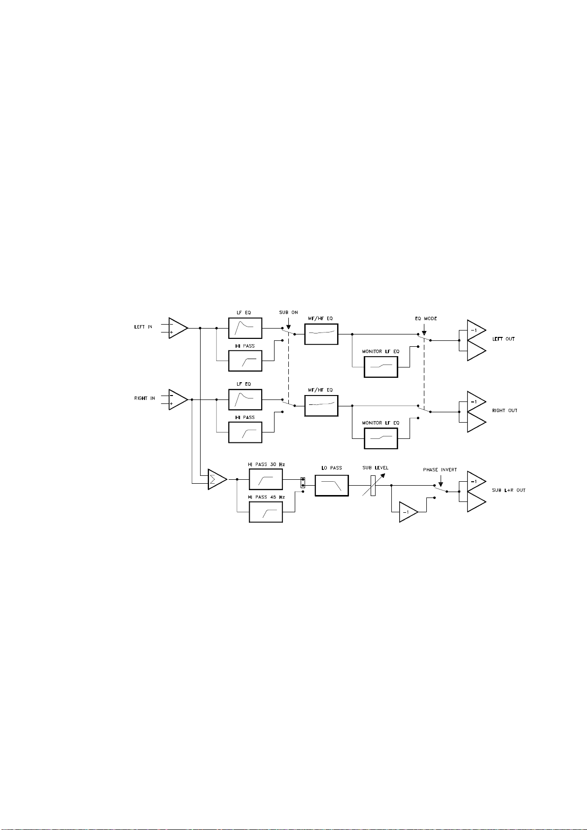
The simplified block diagram (Fig. 4.) shows TX3 operation with and without the subbass system.
When the rear panel ‘SUB ON’ push-button is in the ‘out’ position, the main - left and
right - channels operate full range with the signal passing through the LF EQ section,
resulting in an extension of the bottom end response of the system. This section
consists of a ‘High Q’ 2nd order high pass filter which provides electronic boost
where required and also cuts very low frequencies.
When the button is pushed in, with the red SUB-BASS LED on the front panel
illuminated, the LF EQ section is bypassed and the signal on each main channel is
re-routed via a high-pass filter at 100Hz designed to provide an optimised acoustic
summation for the sub-bass system.
On the sub-bass channel, signals from both left and right inputs are summed
together, and the resulting mono signal is low-pass filtered before being sent through
the level control section.
To sum up: the push-button should be ‘in’ when a sub-bass system is used, ‘out’
when not (T300 running full range without additional sub-bass).
However it should be noted that the sub-bass channel itself is not affected by the
position of the switch, which means that it is possible to have the main system
operating full range while the sub-bass is also in operation. In that configuration both
systems would overlap over a wide bandwidth, with a risk of phase cancellation
ocurring.
The SUB-BASS level control on the front panel can attenuate the sub-bass level by
12dB (-6 to +6). The potentiometer on the front panel is flush mounted in order to
discourage any unauthorised adjustment. A small, flat blade screwdriver is required
to adjust the Sub level.
The EQ MODE MONITOR push button is intended to tailor the bottom end for floor
standing/monitor applications. When the EQ MODE MONITOR button is pressed ‘in’,
the excess bottom end generated due to the close proximity of the floor (when used
4
Page 6
as a ‘wedge’ monitor) is reduced by using a shelving filter. In some situations the
T300 will be used close to a wall (half space loading), or in a corner (quarter space
loading). It may be beneficial to use the EQ MODE MONITOR button in these
instances if the bass frequencies sound ‘overblown’.
The PHASE INVERT push button on the sub channel inverts the polarity of the sub
bass signal. This is mainly implemented to operate the system in conjunction with
Tannoy B400 sub-bass loudspeakers (see B400 user manual).
The GROUND LIFT push button connects/disconnects between the signal ground
and the mains earth, which is linked to the chassis. Using this button may help
eliminate hum caused by ground loops created in the system.
Situated inside the TX3 on the main PCB next to the power supply is a jumper switch
JP1 which allows optimum configuration of the low frequency Hi-Pass filtering
applied to the Sub channel. The ‘45’ Hz position is intended for use with the B400,
while the ‘30 Hz’ position is intended for B950 and B475.
Figure 4. TX3 simplified block diagram.
5
Page 7

TECHNICAL SPECIFICATIONS
Inputs
Outputs
Hum and Noise
Controls and Indicators Front
Rear
Mains supply
Dimensions
Two electronically balanced inputs on 3 pin XLR
connectors.
Input impedance 10 kΩ.
Three electronically balanced outputs on 3 pin XLR
connectors. (Left, Right and Mono Sub)
Output impedance 50 Ω.
Max. level +20 dBV.
-90 dBV, 20 Hz - 20 kHz unweighted
Power on LED.
Sub channel operation LED.
Sub level control potentiometer, -6dB to +6dB.
Sub channel operation switch
EQ mode switch (main channels)
Phase inversion switch (sub channel)
Earth lift switch
IEC mains connector with integral fuse holder.
Voltage selector for 115V or 230V operation (50/60Hz).
Fuse type 5 x 20mm, rating T50mA - 250V for 230V
operation, T100mA - 250V for 115V operation.
1U high, 19” rack mount width
44.5 mm H x 482 mm W x 150 mm D
Weight
1.7 kg
6
Page 8

SERVICING
If any servicing is required, it must only be carried out by qualified personnel. Do not
remove the top cover, as there may be a risk of electric shock.
Fuse replacement.
Disconnect the TX3 from the mains power supply, and pull back the fuse drawer
located at the bottom of the mains input. (A small screwdriver may be helpful.) The
fuse drawer has two compartments, one containing the fuse under operation and the
other a spare. Replacement fuses must be of the 5 x 20-mm type, and of the correct
rating (indicated on the back of the unit).
Having replaced the fuse push the drawer in fully, until it is secured in its original
position.
List of spare parts.
This list does not include any individual electronic parts contained in the unit. For
more detailed information please refer to the Service Manual or consult your local
dealer or distributor.
PART NUMBER DESCRIPTION
Warranty
No maintenance of the TX3 controller is necessary.
All Tannoy electronic components are guaranteed for a period of one year from the
date of manufacture, subject to the absence of, or evidence of, misuse, overload or
accidental damage.
For further information please contact your dealer or the distributor in your country.
If you cannot locate your distributor please contact:
6481 0291
6883 0114
6883 0103
6883 0095
Customer Services
Tannoy Limited
Professional Division
Rosehall Industrial Estate
Coatbridge
Strathclyde ML5 4TF
Scotland
e-mail [email protected]
TX3 User Manual
TX3 Front Panel
TX3 case. Chassis
TX3 case. Top cover
Telephone 01236 420199 (UK) +44 1236 420199 (International)
Fax 01236 428230 (UK) +44 1236 428230 (International)
e-mail [email protected]
DO NOT SHIP ANY PRODUCT TO TANNOY WITHOUT PREVIOUS
AUTHORISATION.
This warranty in no way affects your statutory rights.
7
Page 9

Declaration of Conformity
The following apparatus is/are manufactured in the United Kingdom by Tannoy Ltd of
Rosehall Industrial estate, Coatbridge, Scotland, ML5 4TF and conform(s) to the protection
requirements of the European Electromagnetic Compatibility Standards and Directives
relevant to Domestic Electrical Equipment. The apparatus is designed and constructed such
that electromagnetic disturbances generated do not exceed levels allowing radio and
telecommunications equipment and other apparatus to operate as intended, and, the
apparatus has an adequate level of intrinsic immunity to electromagnetic disturbance to
enable operation as specified and intended.
The apparatus complies with the Principal Elements of the Safety Objectives of the Low
Voltage Directive 73/23/EEC.
Details of the Apparatus: Tannoy Active Crossover/Equaliser
Model Number: TX3
Associated Technical File: EMCTX3
Applicable Standards: EN 50081-1 Emission
EN 50082-1 Immunity
EN 60065:1994
Signed:
Position: Technical Manager
Tannoy Professional
Date: 16
th
July 1998
For Tannoy Ltd
8
Page 10

Tannoy Loudspeakers are manufactured
in Great Britain by :
Tannoy Limited, Coatbridge, ML5 4TF. SCOTLAND
Telephone: +44 (0)1236 420199 Fax: +44 (0)1236 428230
Internet:http://www.tannoy.com
TGI/Tannoy, 300 Gage Avenue, Kitchener, Ontario, CANADA, N2M 2C8
Telephone: (519) 745 1158 Fax: (519) 745 2364
Tannoy Nederland BV, Anthonetta Kuijlstraat 19, 3066 GS, Rotterdam THE NETHERLANDS
Telephone: (010) 2860554 Fax: (010) 2860431
Tannoy is a member of the Group of Companies Issue 1 Part No. 6481 0291
GH 30th March. 1998
 Loading...