

Page 1

Page 2

OPERATIONAL OVERVIEW
1 Introduction
2 Electrical Connection
3 Installation
® Fitting of feet
® Connecting to your system
® Positioning
® Auto Power / Sleep Function
® Overload Protection
® Cleaning
4 Equipment Overview
® TS8
® TS10
5 Technical Specifications
1 Introduction
Owner’s Manual- TS8 & TS10 Subwoofers
These high performance subwoofers have been built and tested with care and precision,
to provide first class performance and reliable operation. To ensure maximum benefit from
ownership and for reasons of safety, please read the following information before using for
the first time. Please complete and return the enclosed warranty registration document - this
does not limit your legal rights.
WARNINGS AND PRECAUTIONS
POWER REQUIREMENTS
Check that the voltage rating displayed on the rear panel is correct for your area before connecting.
If it is incorrect, please refer to your local dealer or authorised service agent, as no user adjustment
is provided.
3
Page 3

OPERATIONAL OVERVIEW
2 Electrical Requirements
IMPORTANT
A mains cable is supplied with an IEC moulded socket at one end and a moulded mains plug at the
other end. Where the moulded plug is fitted with a mains fuse, always replace with the same 5A
rated fuse.
If the fitted plug is unsuitable for your type of outlet sockets, it should be cut off and disposed of safely,
in case it is inserted into a live socket elsewhere. The wires in the mains cable are coloured in accordance
with the following code:
GREEN AND YELLOW EARTH
BLUE NEUTRAL
BROWN LIVE
AS THE COLOURS OF THE WIRES IN THE MAINS CABLE MAY NOT CORRESPOND
WITH THE COLOURED MARKINGS IDENTIFYING THE TERMINALS IN YOUR PLUG, PROCEED
AS FOLLOWS:
} The wire which is coloured GREEN AND YELLOW must be connected to the terminal in
} The wire which is coloured BLUE must be connected to the terminal in the plug which is
} The wire which is coloured BROWN must be connected to the terminal in the plug which
} Ensure that the terminals are tightened securely, and no loose strands of wire are present.
4
the plug which is marked either by the letter E, the earth safety symbol, or coloured GREEN
or GREEN and YELLOW.
marked by the letter N or coloured BLACK.
is marked by the letter L or coloured RED.
Ensure cord grip is clamped over outer sheath of cable, rather than over the wires.
Page 4

OPERATIONAL OVERVIEW
2 Electrical Requirements
FUSE PROTECTION
An additional mains fuse is provided in the IEC power inlet on the back of the loudspeaker, which can
only be removed with the power cord unplugged. This must be replaced by a fuse of the same type
and rating (see Specifications or refer to rear panel).
FOR YOUR OWN PROTECTION
} Store complete packaging in case it is needed for re-use.
} Never expose the unit to moisture, water and extremes of temperature or humidity.
} Never remove the rear panel of the unit, as there is a risk of electric shock.
} There are no user serviceable parts inside the unit. Always refer servicing to your
} Avoid violent shocks to the unit during packing or transportation.
} Do not plug the unit into the mains until all other connections have been made and checked.
} Due to the powerful drive unit magnet, do not place within 1m of a television or
Do not operate with the rear panel close to a radiator or heater.
Tannoy dealer or authorised service agent.
computer monitor.
5
Page 5

OPERATIONAL OVERVIEW
3 Installation
FITTING OF FEET
Screw the four cones into the inserts on the base of the cabinet. Spikes and lock nuts are provided to
provide stability when used on a carpet. For use on a wooden floor, the spikes should be inverted.
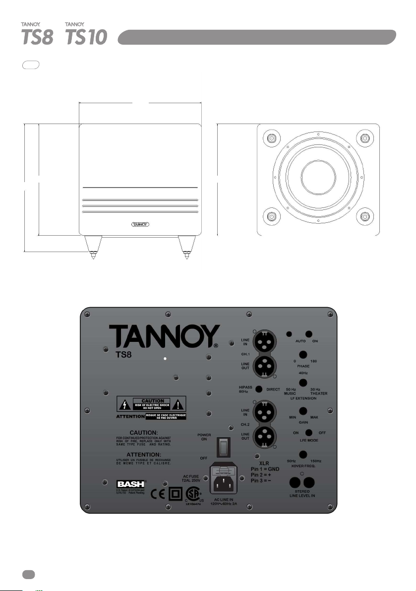
CONNECTING TO YOUR SYSTEM
For 2 channel stereo use, if your preamplifier has a spare set of outputs, connect left and right to the
subwoofer L and R phono inputs using screened cable. Alternatively for AV use, take the subwoofer
output from your AV processor, and plug into either LINE IN phono socket.
Users with balanced systems may make use of the XLR inputs. With this option, a LINE OUT facility is
provided, to feed the main speaker pair. This can be selected by the adjacent switch to be either a
DIRECT feed, or provide an 80Hz HIPASS function. The latter setting is recommended for smaller main
speakers.
SETTING UP
} Ensure the main POWER switch is in the OFF position.
} You can operate these subwoofers in two modes, AUTO and ON continuously, using the
} Status is confirmed by the power light, which glows red in AUTO standby, but is
switch provided. In AUTO, the unit remains OFF until an input signal is detected.
otherwise green.
AV SYSTEMS:
Firstly set GAIN (volume) control to MIN, and LFE MODE switch to ON. This will bypass the unit’s
internal crossover, with this function now provided for within the AV processor. The XOVER FREQ.
Control will no longer be functional. Set the PHASE control to 0 0.
The LED will turn green when switched ON, or when a signal is detected in AUTO mode.
Set the LF XTENSION control to mid position and play some music or other material through the
system and slowly increase the input level control until roughly the correct amount of bass is present.
If this does not prove possible, rotate the PHASE control clockwise, which with some speakers and
rooms will give increased bass output. Moving the LF XTENSION control anticlockwise towards the
MUSIC position will give a deeper more extended bass, while moving it clockwise towards the
THEATRE position will increase the impact of movie sound effects. Fine adjustment of the controls
will take a little time using a range of different programme material.
Remember that the object of a subwoofer is to enhance the output of your main speakers, not
overpower it.
6
Page 6

OPERATIONAL OVERVIEW
3 Installation
2 CHANNEL STEREO
Operation is basically the same as above, except the LFE switch should be set to OFF, and the XOVER
FREQ. control must be set to suit your main speakers. If you know the lower roll-off frequency of your
speakers (as given in the manual), set the control to this value as a starting point. If not, set the control
to mid position. Using a range of music, adjust the control to give the smoothest integration between
the main speakers and the subwoofer. The LF XTENSION control should be set to MUSIC, but some
deviation away from this setting may be preferred depending on the main speakers and room.
POSITIONING
As a subwoofer produces low frequencies only, it is difficult to detect its location by ear. It can therefore
be placed anywhere in the room, but it is worth experimenting to find the optimum position. Bass output
will increase next to a wall or especially in a corner; so use the GAIN control to compensate if moving
your subwoofer around.
AUTO POWER/ SLEEP FUNCTION
These subwoofers can be left permanently on in AUTO mode, under which conditions they will revert
to ‘sleep’ mode after approximately 12 minutes. If not using your subwoofer for some time, switch OFF
and remove the power cable from the mains outlet.
When unused for some time, such as vacations, set the main power switch to OFF and unplug the unit
from the mains.
OVERLOAD PROTECTION
All Tannoy TS subwoofers are provided with circuitry to limit the maximum sound output, in order to
eliminate audible distortion. This circuitry will normally operate unnoticed. If however distortion is heard,
this indicates the unit is being severely overloaded, and to avoid damage, the input level should be
reduced immediately.
CLEANING
Dust the enclosure with a dry lint free cloth, which may be moistened to remove any marks.
Do not use any solvent-based chemicals.
7
Page 7
OPERATIONAL OVERVIEW
4 TS8 Equipment Overview
280
292
255
255
8
Page 8

OPERATIONAL OVERVIEW
4 TS10 Equipment Overview
286
323
286
288
9
Page 9

OPERATIONAL OVERVIEW
5 Technical Specification TS8 TS10
Output Power 200W RMS 300W RMS
Low Frequency Response (-6dB) 32Hz 29Hz
Limit for usable output 18Hz 16Hz
Inputs 2 x line level phono 2 x line level phono
Outputs 2 x XLR balanced 2 x XLR balanced
Input Filter 2nd order low pass, 2nd order low pass,
Auto Mute After approximately 12 mins, After approximately 12 mins,
Driver Type 200mm (8”) 250mm (10”)
Enclosure Type Closed box Closed box
Enclosure Volume 12.5 litre/ 0.45cu.ft 16.75 litre/ 0.6cu.ft
Additional Features Phase control Phase control
LF extension control LF extension control
Enclosure (H x W x D) 292 x 280 x 255mm 323 x 286 x 286mm
Including feet 11.5” x 11.5” x 10” 12.7” x 11.3” x 11.3”
Enclosure Weight 7.0kg/ 15.4lbs 9.5kg/ 21lbs
Mains Voltage 120V nominal AC ~, 60Hz 230V nominal AC ~, 50Hz
Mains Fuse 120V- T2AL/250V 120V - T3.15AL/250V
Maximum Power Consumption 275VA 416VA
2 x XLR balanced 2 x XLR balanced
(direct or 80Hz HIPASS) (direct or 80Hz HIPASS)
50Hz – 150Hz, -6dB. 50Hz – 150Hz, -6dB.
in absence of input signal in absence of input signal
Crossover defeat switch Crossover defeat switch
for LFE operation for LFE operation
Soft limiting to avoid overload Soft limiting to avoid overload
230V- T1AL/250V 230V - T1.6AL/250V
Warranty
Tannoy adopts a policy of continuous improvement and product specification is subject to change.
E. & O.E.
This equipment has undergone safety and EMC testing, and complies with the European Low Voltage
Directive and Electromagnetic Compatibility Directive, together with the requirements of the Canadian
Standards Association (CSA).
10
Page 10

Tannoy Loudspeakers are designed and manufactured in Great Britain by:
Tannoy Ltd, Rosehall Industrial Estate, Coatbridge,
North Lanarkshire, ML5 4TF, SCOTLAND
Telephone: +44 (0)1236 420199 Fax: +44 (0)1236 428230
Tannoy North America Inc, Suite 1. 335 Gage Avenue, Kitchener,
Ontario, CANADA, N2M 5E1
Telephone: (519) 745 1158 Fax: (519) 745 2364
Check periodically for the latest manual revision that will always available for download from
www.tannoy.com The revision number of this manual is located below
Issue 1 Software Version 1.12 Part No. XXXX XXXX
GH 26Aug2003
 Loading...