

Tannoy TMA120 Operating Instructions Manual

TABLE OF CONTENTS
Front Panel Features
Rear Panel Features
Modifications
Applications
Specifications
Block Diagram
Warranty Statement
Appendices
TMA120
OPERATING INSTRUCTIONS
pg. 2
pg. 3
pg. 5
pg. 6
pg. 10
pg. 10
pg. 11
pg. 12
INTRODUCTION
The
TMA120
input mic/line mixer with 120 Watt amplification. Mixing
functions include mic/line/telephone inputs, selectable automatic
& manual channel muting, channel priority assignment, remote
level control, tone control, a built-in compressor, an internal
chime, phantom power, and extensive output patching. The
amplifier includes an output transformer, and provides rated
power into direct or distributed speaker systems.
TMA120 features include:
• integrated mixer, power amplifier, and output transformer
• five electronically balanced microphone/line input channels
• one transformer balanced microphone/line/tel input channel
• rear panel trim control & pad switch on each input channel
• +24 Volt phantom power selectable on each input channel
• input isolation transformer option on mic/line input channels
• automatic muting of selected channels (-10, -20, or -40dB)
• automatic muting triggered by selected "priority" channels
• manual muting of selected channels (-10, -20, or -40dB)
• manual muting triggered from remote contact closures
• remote control of master level via rear panel terminals
• integral output compressor with rear panel threshold control
• recessed treble & bass controls plus "loudness" & "low-cut"
• two insert points for signal processing and remote control
• two line-outs and one stack-in for system interconnections
• 120 Watts into direct or distributed systems
• front panel indicators for power, fault, signal, and peak
• internal 'pre-announcement' chime tone with level control
• input/output connections provided on barrier strip terminals
• integral security cover and removable rack-wing/handles
• covered by two year warranty
• marked, UL and C-UL (UL Canada) listed
commercial mixer/amplifier combines a versatile 6-
TANNOY LIMITED, PROFESSIONAL DIVISION, COATBRIDGE, ML5 4TF. SCOTLAND
ELEPHONE: +44 (0) 1236 420199 FAX: +44 (0) 1236 428230 E-MAIL: prosales@tannoy.com
T
A M
EMBER OF THE TGI PLC GROUP OF COMPANIES

FRONT PANEL FEATURES
Level (Channels 1~6):
These controls adjust the
amount of signal sent from the individual input
channels to the mixer output. Optimum Level setting
is near the 12 o'clock position (unity gain).
Level (Master): This control adjusts the amount of
signal sent from the mixer output to the amplifier
input. The Master Level control is used to adjust the
overall volume of the system.
Low Cut: This switch inserts a low cut filter at the
amplifier input.
Loudness Contour: This switch inserts a loudness
filter at the mixer output (+6dB @ 100Hz & +4dB @
10kHz). The Loudness filter provides tonal
compensation when operating with low-level music
signals.
Tone Control: This switch enables the Bass &
Treble controls.
Bass: This screwdriver control adjusts the lowfrequencies ("Bass") at the mixer output (±10dB @
100Hz).
Treble:
This screwdriver control adjusts the highfrequencies ("Treble") at the mixer output (±10dB @
10kHz).
Peak Indicator:
This red LED flashes when signal
levels at the amplifier output have reached
maximum. Occasional flashes of the Peak Indicator
are acceptable, however, a continuously lit LED may
indicate an excessive level setting.
Signal Indicator:
This yellow LED remains lit when
signal is present at the amplifier output.
Fault Indicator:
This red LED lights to indicate fault
conditions due to overheating, DC offset voltage, or
failure of low-voltage power. The Fault Indicator will
light for 3-5 seconds at turn-on, and then go off if no
fault is detected. Some faults (such as overheating)
will correct themselves when the unit has been
turned off awhile. If the Fault Indicator remains lit
when the unit is turned back on, contact your local
dealer.
On Indicator: This green LED remains lit when AC
power is applied to the unit.
Power Switch: This switch applies AC power to the
unit.
2
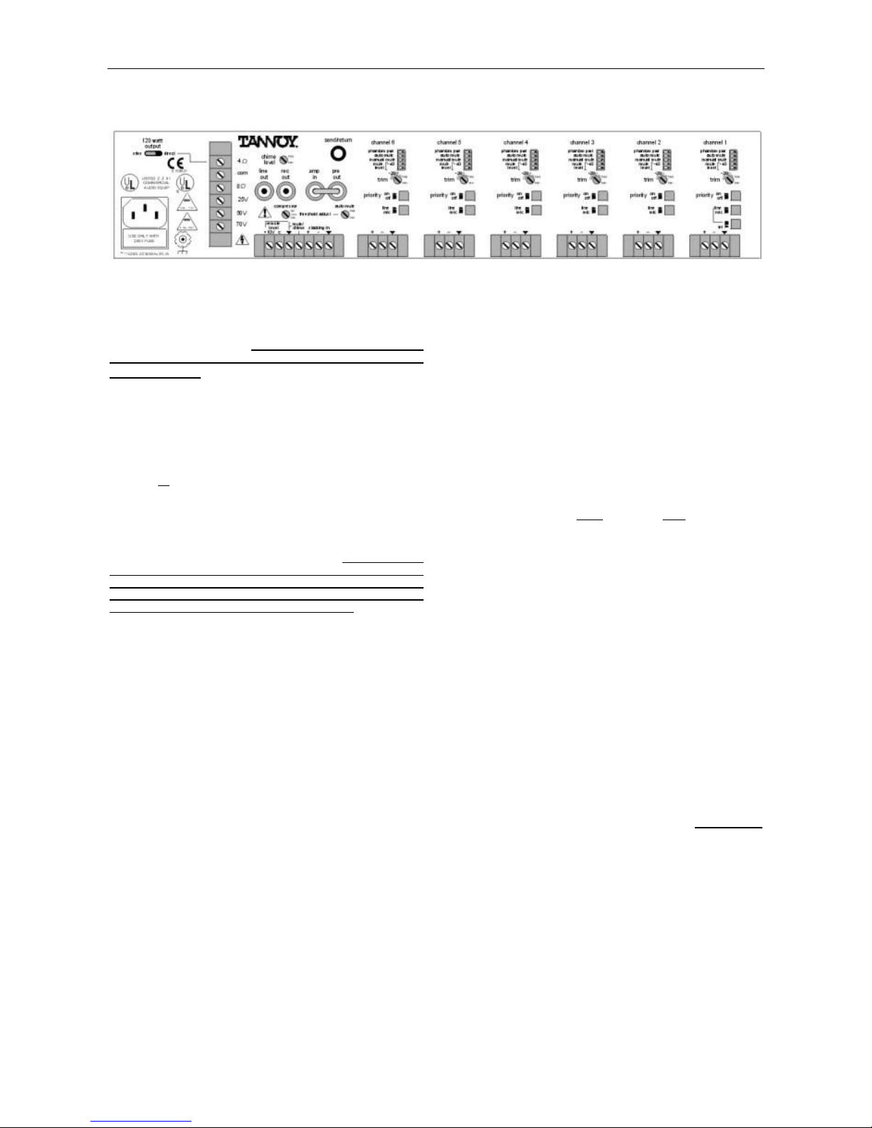
REAR PANEL FEATURES
Power Entrance: This receptacle accepts a 3-
prong AC power cord.
DEFEAT THE GROUND PRONG, AS THIS CONSTITUTES A
SHOCK HAZARD. The removable lower portion of the
WARNING: DO NOT REMOVE OR
receptacle holds the AC fuse. NOTE: See AC Fuse
on page 6 for replacement by qualified personnel. A
chassis ground post is provided (next to the
receptacle) for system grounding.
Output Selector: This switch selects either direct
output or
amplifier. The direct output is from the 4
transformer coupled output from the
terminal.
Output Terminals: These screw terminals provide
connection for speaker loads (4
70V, or 100V) at the amplifier output.
LOUDSPEAKER OUTPUTS POSE A RISK OF HAZARDOUS
ENERGY. LOUDSPEAKER CONNECTIONS MUST BE MADE
PROPERLY. THE OUTPUT TERMINAL COVER MUST BE
INSTALLED WHEN THE DEVICE IS ENERGIZED.
, 8, 25V, 50V,
WARNING: THE
Chime Level: This control adjusts the volume level
of the chime tone (see Mute/Chime on next page).
To turn the chime tone off completely, set this control
to the fully counter-clockwise position.
Send/Return:
This 3-conductor TRS 1/4" Phone
jack provides an insert point for signal processing or
remote control devices. It is wired with Tip as send,
Ring as return, and Sleeve as ground. Send/Return
is after Stacking In, Loudness, & Tone, but before
Compressor, Master Level, & Low Cut. Send/Return
is a switching jack, which interrupts the signal flow
only when a plug is inserted.
Line Out: This RCA phono jack provides an
unbalanced line-level output from the mixer. Line
Out is after Stacking In, Loudness, Tone,
Compressor, & Master Level, but before Low Cut.
Rec Out: This RCA phono jack provides an
unbalanced line-level output from the mixer. Rec
Out is after Stacking In, but before Loudness, Tone,
Compressor, Master Level, & Low Cut.
Pre Out: This RCA phono jack provides an
unbalanced line-level output from the mixer. Pre Out
is after Stacking In, Loudness, & Tone, but before
Compressor, Master Level, & Low Cut. Pre Out and
Amp In may be used together as an insert point for
signal processing or remote control devices.
Remove jumper before connecting devices. To
connect Pre Out to both
Amp In and an external
device, a parallel (‘Y’) cable must be used.
Amp In: This RCA phono jack provides an
unbalanced line-level input to the amplifier. Amp In
is after Stacking In, Loudness, & Tone, but before
Compressor, Master Level, & Low Cut. Pre Out and
Amp In may be used together as an insert point for
signal processing or remote control devices.
Remove jumper before connecting devices.
Compressor: This control adjusts the threshold
level at which the internal compressor circuit is
activated. The internal compressor has a fixed
compression ratio of 4:1, and is used to reduce
peaks in output signal level, as well as to moderate
volume differences between loud and soft signals.
Auto Mute: This control adjusts the threshold level
at which signals from "priority" channels will
automatically trigger muting of selected non-priority
channels (see Assignment & Priority below).
3

Remote Level:
These two screw terminals (plus "
ý
")
provide remote volume control of the master level.
An internal voltage controlled amplifier (VCA) allows
remote control from up to 2000 ft (600m) away,
using any 5k~50k
linear taper potentiometer and/or
switch to provide adjustment and/or muting of the
master level. Potentiometers are wired with highside to "+10V", low-side to "
ý
", and wiper to "C".
Switches simply connect (or disconnect) "+10V" to
ý
"C", and do not require a ground (‘
’) connection.
NOTE: The factory installed jumper (between
"+10V" & "C") must
control is not
being used.
be in place when a remote
Mute/Chime:
This screw terminal (plus "
ý
") allows
manual muting of any selected channels, via an
external switch or contact closure (see Assignment &
Priority below). When the Chime Level control is
turned up (on), a pre-announcement chime tone will
also be activated by the switch or contact closure.
Stacking In: These screw terminals provide a
balanced line-level input to the mix bus, for input
expansion. Stacking In is before Loudness, Tone,
Compressor, Master Level, & Low Cut. For
unbalanced input, wire high to (+) and ground to
both (-) & (
ý
).
Assignment: These five DIP switches are used to
assign specific functions to the individual channels.
To assign a function, move the respective switch to
the left. Phantom Pwr
assigns +24 Volts DC
phantom power to the channel input, for powering
condenser microphones.
DAMAGE TO EQUIPMENT, ASSIGN PHANTOM POWER ONLY
ON CHANNELS WHICH ARE SELECTED FOR 'MIC' INPUT
AND WHICH REQUIRE PHANTOM POWER.
CAUTION: TO AVOID
Auto Mute
assigns a (non-priority) channel to be muted
whenever signal is present in any "priority" channel.
Manual Mute
assigns a channel to be muted
whenever the Mute/Chime terminals are shorted
together via a switch or contact closure. Mute Level
assigns the amount of muting (-10dB, -20dB, or 40dB) which is applied to a channel, when triggered
by either Auto Mute or Manual Mute. NOTE: -10dB
muting will occur when both switches are to the right.
-40dB muting will occur when both switches are to
the left.
This control adjusts the input gain of the
Trim:
channel, to compensate for various input signal
levels. Once the Line/Mic switch has been set to the
proper position (see Line/Mic below), the Trim
control should be adjusted so that peaks in signal
level do not cause distortion at the channel input.
Priority: This switch assigns a channel to "priority".
When signal is present in a "priority" channel, any
(non-priority) channels which are assigned to Auto
Mute will be muted by their selected amount. NOTE:
A "priority" channel cannot
"priority" channel, but a "priority" channel can
be auto muted by another
be
manual muted.
Line/Mic: This switch selects the proper impedance
and gain for either microphone or line-level input
signals. Depress the switch for line-level input.
Release the switch for microphone input. On
Channel 1, the Tel switch (see Tel below) must be
released for the Line/Mic switch to operate.
Tel (Channel 1 only): This switch selects the
proper impedance and gain for input from 600 ohm
sources. The input for Channel 1 includes an
isolation transformer, which allows connection to
most telephone system audio ports.
Inputs: These screw terminals provide a balanced
input connection for the channel. For unbalanced
input, wire high to (+) and ground to both (-) & (
ý
).
The input for Channel 1 includes an isolation
transformer.
4
 Loading...