

Page 1

OWNER’S MANUAL
TFX SUBWOOFER MANUAL_01
Page 2

CONTENTS
WARRANTY 02 SUBWOOFER CONNECTION 05
IMPORTANT SAFETY INSTRUCTIONS 03 SETTING UP 06
WARNING 04 POSITIONING 06
STRONG MAGNETIC FIELD 04 AUTO POWER / SLEEP FUNCTIONS 06
FCC INFORMATION (USA ONLY) 04 TECHNICAL SPECIFICATIONS 07
INTRODUCTION 05
WARRANTY
No maintenance of this Tannoy Subwoofer is necessary.
This equipment has been produced and tested with care and precision. It is built to give rst class service and carries a
2 year warranty on the electronics and 5 years on the drive unit. If the equipment proves to be defective within this period
for any reason other than accident, misuse, unauthorised modication or fair wear and tear, Tannoy will repair any such
defect or, at our option, replace it without charge for parts, labour or return carriage. This warranty is given in addition to
the customer’s statutory rights.
Please register your Tannoy product online at www.tannoy.com.
If you suspect a problem with your subwoofer, please contact your local Tannoy dealer who will be able to advise on
appropriate action. If you require further assistance, then we ask you to deal directly with your local Tannoy distributor. If
you cannot locate your distributor, please contact us directly:
Customer Services, Tannoy Ltd., Rosehall Industrial Estate, Coatbridge, Strathclyde ML5 4TF, Scotland
Telephone: 01236 420199 (National)
+44 1236 420199 (International)
Fax: 01236 428230 (National)
+44 1236 428230 (International)
E-mail: enquiries@tannoy.com
Do not ship any product to Tannoy without previous authorisation.
Our policy commits us to incorporating improvements to our products through continuous research and development.
Please conrm current specications for critical applications with your supplier.
02_ TFX SUBWOOFER MANUAL
Page 3
IMPORTANT SAFETY INSTRUCTIONS
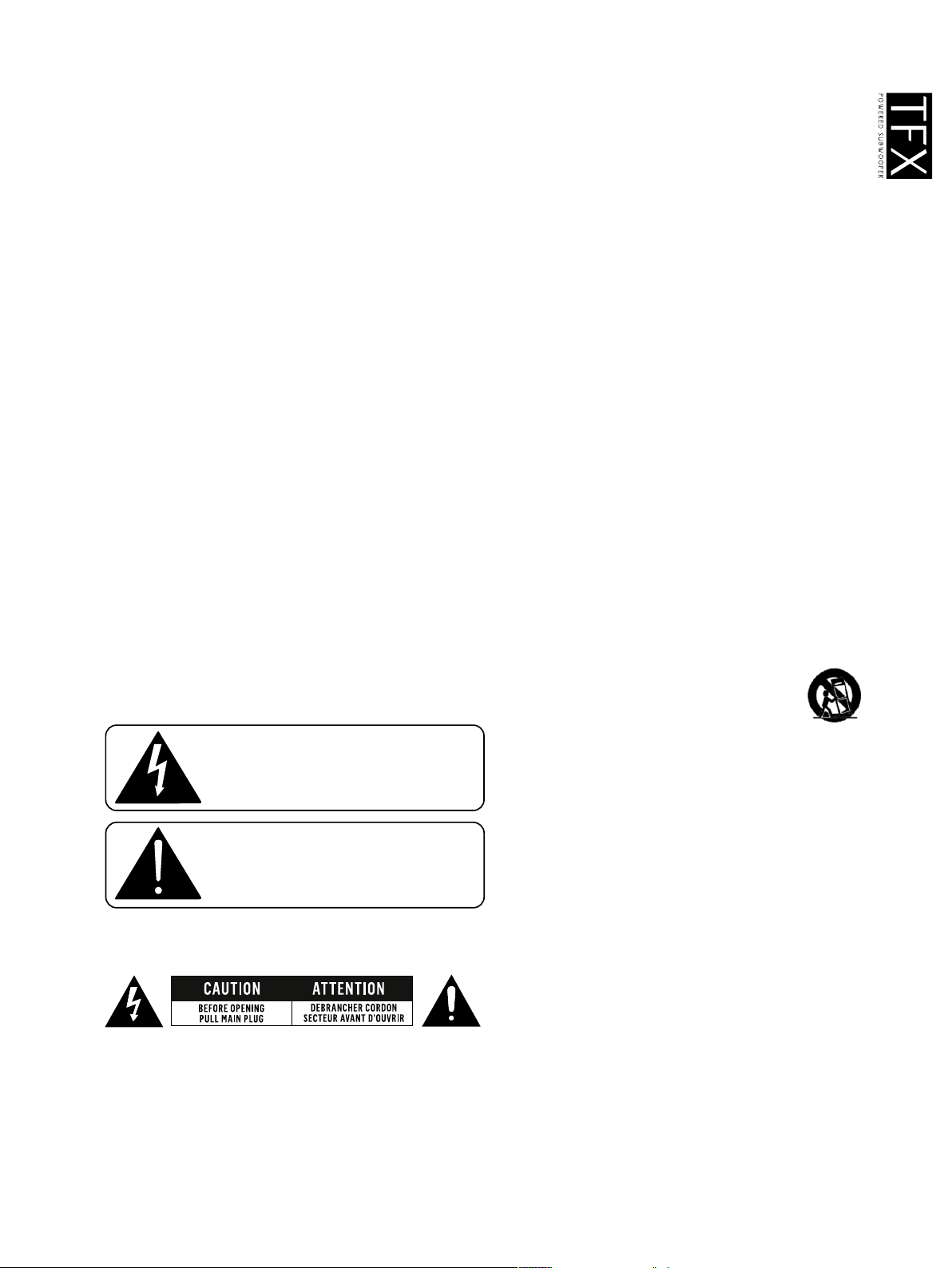
The lightning ash with arrowhead symbol within an
equilateral triangle, is intended to alert the user to the
presence of uninsulated "dangerous voltage " within the
product's enclosure that may be of sucient magnitude
to constitute a risk of electric shock to persons.
The exclamation point within an equilateral triangle is
intended to alert the user to the presence of important
operating and maintenance (servicing) instructions in the
literature accompanying the product.
1. Read these instructions.
2. Keep these instructions.
3. Heed all warnings.
4. Follow all instructions.
5. Do not use this apparatus near water. To reduce the risk of re or electric shock, this apparatus should not
be exposed to rain or moisture and objects lled with liquids, such as vases, should not be placed on
this apparatus.
6. Clean only with dry cloth.
7. Do not block any ventilation openings. Install in accordance with the manufacturer’s instructions. This
apparatus is not suitable for in wall mounting.
8. Do not install near any heat sources such as radiators, heat registers, stoves, or other apparatus (including
ampliers) that produce heat.
9. Do not defeat the safety purpose of the polarized or grounding-type plug. A polarized plug has two blades with
one wider than the other. A grounding type plug has two blades and a third grounding prong. The wide blade
or the third prong are provided for your safety. If the provided plug does not t into your outlet, consult an
electrician for replacement of the obsolete outlet.
10. Route the power cord to prevent risk from being walked on or pinched by objects, particularly at plugs,
convenience receptacles, and the point where they exit from the apparatus.
11. To completely disconnect this equipment from the mains, disconnect the power supply cord plug from
the receptacle.
12. The mains plug of the power supply cord shall remain readily operable.
13. Unplug this apparatus during lightning storms or when unused for long periods of time.
14. This apparatus has been equipped with a rocker type AC mains switch. The switch is located on the rear panel
and should remain readily accessible to the user.
15. Only use attachments/accessories specied by the manufacturer.
16. Refer all servicing to qualied service personnel. Servicing is required when the apparatus has been damaged
in any way, such as power-supply cord or plug is damaged, liquid has been spilled or objects have fallen into
the apparatus, the apparatus has been exposed to rain or moisture, does not operate normally, or has
been dropped.
17. Use only with the cart, stand, tripod, bracket, or table specied by the manufacturer, or sold with the apparatus.
When a cart is used use caution when moving the cart/apparatus combination to avoid injury from tip-over.
The below warning is located on the rear of the unit:
TFX SUBWOOFER MANUAL_03
Page 4

WARNING:
FAILURE TO FOLLOW THESE SAFETY INSTRUCTIONS COULD RESULT IN FIRE, ELECTRIC SHOCK, OR OTHER
INJURY OR DAMAGE.
Voltages in this equipment are hazardous to life. No user-serviceable parts inside. Refer all servicing to qualied service
personnel.
Check that the voltage rating displayed on the rear panel is correct for your area before connecting. If it is incorrect,
please refer to your local dealer or authorised service agent. Use only with the detachable power cord supplied with the
apparatus, or by your local distributor or dealer.
STRONG MAGNETIC FIELD
Due to the powerful drive unit magnet, do not place within 1 metre (3 foot) of a cathode ray tube (CRT) television or
monitor. There is no issue with plasma and LCD devices.
FCC INFORMATION (USA ONLY)
CAUTION: Any change or modication to this unit could void your authority to operate this equipment, granted by
the FCC.
This apparatus has been tested and found to comply with the limits of a Class B digital device, pursuant to Part 15 of
the FCC rules. These limits are designed to provide reasonable protection against harmful interference in residential
installations. This equipment generates, uses and can radiate radio frequency energy and, if not installed and used
according to these instructions, may cause harmful interference to other electronic equipment. However, there is no
guarantee that interference will not occur in all installations. If this equipment does cause harmful interference to radio
or television reception, which can be determined by turning the equipment off and on, the user is encouraged to try to
correct the interference by one or more of the following measures:
• Reorient or relocate the receiving antenna.
• Increase the distance between the equipment and the receiver.
• Connect the equipment to an outlet on a different circuit than the receiver.
• Consult your dealer or an experienced radio/ television technician for help.
This equipment has undergone safety and EMC testing, and complies with the European Low Voltage Directive 73/23/
EEC and Electromagnetic Compatibility Directives 89/336/EEC and 2004/108/EC.
This equipment complies with the European EuP Eco-design directive, with standby mode power consumption not
exceeding 0.5W.
04_ TFX SUBWOOFER MANUAL
Page 5

INTRODUCTION
Thank you for selecting Tannoy loudspeakers developed in the UK by our dedicated team of design engineers. They
are the choice of discriminating music lovers the world over. Musical excellence is designed into our loudspeakers from
the start. Careful selection of the very best components combined with strict quality control procedures in the production
process ensures this level of excellence is maintained. To gain maximum performance from your loudspeakers, please
take time to read this owner’s manual in full before installation.
Loudspeakers are electromechanical devices that ‘run-in’ through use; performance will therefore improve after an initial
period of 24hrs use. Once they have been further run-in over a longer period, there will be a clear enhancement of
performance.
We are condent that you will continue to enjoy your new Tannoy subwoofer for many years to come.
SUBWOOFER CONNECTION - USING LINE LEVEL INPUT
TO AMPLIFIER SUB OUTPUT
SUBWOOFER CONNECTION - USING HIGH LEVEL INPUTS
+
AMPLIFIER R OUTPUT
-
-
AMPLIFIER L OUTPUT
+
TFX SUBWOOFER MANUAL_05
Page 6

CONNECTING THE SUBWOOFER TO YOUR SYSTEM
The TFX system subwoofer may be connected in any one of the following ways:
LINE LEVELS
• Using the subwoofer output on your A/V receiver or decoder connect a single RCA interconnect to either the left or
right line input on the subwoofer rear panel. This is the ideal connection type as the subwoofer output contains the
low frequency information from all channels.
• If no subwoofer or spare line outputs exist you may connect using a Y-split connector on the main preamplier output
connections. Use a Y-split on both right and left outputs and connect these via an RCA interconnect to the left and
right inputs on the subwoofer rear panel.
• Alternatively, if your preamplier has a spare set of line level outputs, connect left and right to the TFX subwoofer
L and R inputs using screened cable.
HIGH LEVELS
• Use your amplier’s speaker out terminals. To accommodate the connection of two sets of cables, red (+) goes to red
(+), and black (-) to black (-), twist wires together and connect to the amplier terminals.
• Alternatively use the ‘A & B’ speaker outputs on the amplier if provided - A to your main speakers and B to the TFX
subwoofer. Do this using a length of speaker cable for each channel, wire your amplier outputs to the HIGH LEVEL
input terminals, on the subwoofer amplier panel. Ensure there are no stray wire strands that could possibly short
together and damage both the amplier and subwoofer.
WARNINGS
• Double-check all connections before switching on the TFX Subwoofer and your amplier.
• Ensure that the polarity of the speaker cables from your amplier to the subwoofer is correct - failure to observe this will
result in damage to your amplier.
SETTING UP
Ensure the POWER switch is in the OFF position. You can operate the TFX subwoofer in two modes, AUTO and ON.
Set to AUTO, the unit remains switched off until a signal is present (power saving), set to ON the unit runs continuously.
Connect the TFX subwoofer to a convenient mains socket using the lead and plug supplied.
Set the SFX subwoofer VOLUME to MIN, PHASE SWITCH to 0°, CROSSOVER to AV/LFE. Set your 5.1 or 6.1 receiver/
decoder to SMALL SPEAKERS, LFE or SUB output to ON and play a favourite disc. Switch the SFX subwoofer to ON
and set the VOLUME to AV / LFE. Assess the bass signal strength and adjust VOLUME accordingly. The purpose of
a subwoofer is to enhance the bass or low frequencies but not to overpower the music or lm dialogue. Set up can be
checked by using the noise signal calibration facility in most 5.1 or 6.1 receivers / decoders.
POSITIONING
As the TFX subwoofer produces low frequencies only, it is difcult to detect its location by ear. It can therefore be placed
anywhere in the room, but optimum performance will be gained by locating the subwoofer between the front pair of
speakers. Bass output will increase next to a wall or especially in a corner; so use the volume control to compensate if
moving your subwoofer around.
AUTO POWER / SLEEP FUNCTIONS
The SFX subwoofer can be left permanently on in AUTO mode, under which conditions it will revert to ‘sleep’ mode after
approximately 20 minutes. If not using your subwoofer for some time, switch off and remove the power cable from the
mains outlet.
06_ TFX SUBWOOFER MANUAL
Page 7

TECHNICAL SPECIFICATIONS
SUBWOOFER
PERFORMANCE
Power output 100 Watts
Frequency response (-6dB) 45 Hz - 140 Hz
Driver 200 mm (8.00”) paper cone
Inputs Twin line or speaker level
Power requirements 120 VA max
Fuse ratings AC100-120 V / 60 Hz - Fuse: T1.6A L / 250 V
AC 220-240 V / 50 Hz - Fuse: T800mA L / 250 V
Additional features ON / OFF/ AUTO power function
Weight 9.0 kg (20.0 lbs)
Dimensions H x W x D 345 x 250 x 370 mm (13.58 x 9.84 x 14.57”)
Finish Black
White
TFX SUBWOOFER MANUAL_07
Page 8

Tannoy United Kingdom T: 00 44 (0) 1236 420199 E: enquiries@tannoy.com
Tannoy Deutschland T: 00 49 (180) 1111 881 E: anfragen@tannoy.com
TC|Group International T: 00 45 8742 7000 E: info@tcgroup-international.com
TC|Group Americas T: 00 1 (519) 745 1158 E: info@tcgroup-americas.com
Tannoy adopts a policy of continuous improvement and product specication is subject to change.
08_ TFX SUBWOOFER MANUAL
6481 0591 / 0810
 Loading...