

Page 1
QFLEX 32LS
Mounting and Installation Guide
Page 2

QFLEX 32LS Mounting and Installation Guide rev 2.2.0
2
Page 3

Table of Contents
Page
1. Rigging and Safety Procedures.....................................................................................4
2. Fix bracket to wall surface ............................................................................................5
3. QFlex 32LS Assembly .................................................................................................... 5
4. Wall Bracket Mounting Centres ...................................................................................7
Table of Contents
QFLEX 32LS Mounting and Installation Guide rev 2.2.0
3
Page 4

1. Rigging and Safety Procedures
1. Rigging and Safety Procedures
The Tannoy Professional hardware covered in this guide has been designed to offer a quick, simple, cost
effective and secure solution for mounting specific Tannoy Professional loudspeakers. This hardware
has been designed and manufactured with a high safety load factor for its specific role. To ensure the
safest possible use of the hardware covered in this guide, it must be assembled in strict accordance
with the instructions specified.
The information in this instruction guide relating to the assembly and the safe use of these accessories
must be understood and followed. The installation of Tannoy Professional loudspeakers - using the
dedicated hardware - should be carried out only by fully qualified installers, in accordance with all the
required safety codes and standards that apply at the place of installation.
WARNING: As the legal requirements for mounting, suspending, hanging, flying or rigging equipment
change from country to country, please consult your local safety standards office before installing any
product. We also recommend that you thoroughly check any laws and bylaws prior to installation. Tannoy
Professional hardware has been designed for use with specific Tannoy Professional loudspeakers, and
is not designed or intended for use with any other Tannoy Professional products, or any other devices.
Using Tannoy Professional hardware for any purpose other than that indicated in this guide is considered
to be improper use. Such use can be very dangerous: overloading, modifying, damaging, or assembling
in a manner other than that clearly stated in the Operation Manual will compromise safety.
The component parts of any Tannoy Professional hardware device must only be assembled using the
accessory kits supplied and in strict compliance with the Operation Manual. The use of other accessories
or non-approved methods of assembly may result in an unsafe hardware system by reducing the load
safety factor. Welding, or any other method of permanently fixing hardware components together or to
the integral fixing points in the cabinet, should never be used.
Whenever a Tannoy Professional loudspeaker is fixed to a surface using a Tannoy Professional hardware
device, the installer must ensure that the surface is capable of safely and securely supporting the load.
The hardware employed must be safely, and securely attached both to the loudspeaker and also to the
surface in question, in accordance with the Operation Manual, using only the fixing holes provided as
standard and covered in the manual. Secure fixings to the building structure are vital. Seek help from
architects, structural engineers or other specialists if in any doubt.
QFLEX 32LS Mounting and Installation Guide rev 2.2.0
4
Page 5

2. Fix bracket to wall surface
2. Fix bracket to wall surface
Whenever a Tannoy Professional loudspeaker is fixed to a surface using a Tannoy Professional Hardware
device, the installer must ensure that the surface is capable of safely and securely supporting the
load. The hardware employed must be safely, and securely attached both to the loudspeaker and also
to the surface in question, using only the fixing holes provided as standard and in accordance with
the instructions in this document. Secure fixings to the building structure are vital. Seek help from
architects, structural engineers or other specialists if in any doubt.
3. QFlex 32LS Assembly
It is recommended that you assemble the column horizontally on a flat surface. Lay some cloth or
cardboard on the surface to avoid scratching the surface of the product during the assembly process.
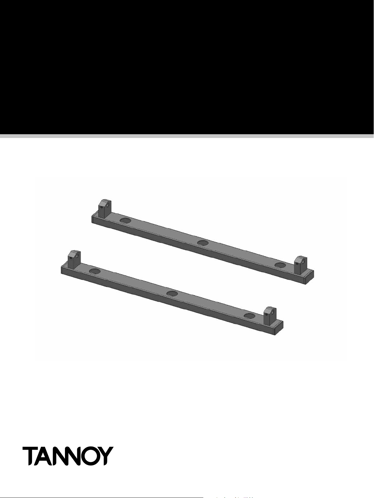
In the hardware pack you will find two wall brackets and joining hardware consisting of two heavy
joining plates with hinge points, four small link bars and M4 Phillips screws.
Place each module in its respective position on the assembly area keeping them slightly spaced apart.
Take the flying RJ45 connector in the lower module and insert it into the RJ45 socket in the middle
module. Take the flying AC mains connector in the lower module and insert it into the female connector
in the middle module. Take the flying RJ45 connector in the middle module and insert it into the RJ45
socket in the top module. Take the flying AC mains connector in the middle module and insert it into the
female connector in the top module.
CAT 5
POWER CORD
QFLEX 32LS Mounting and Installation Guide rev 2.2.0
5
Page 6

3. QFlex 32LS Assembly
Align the three columns together as shown below.
STAGE 2
STAGE 1
STAGE 3
Attach the joining plates in the three stages
as shown. Only one wall bracket it required
to mount the two modules. For exibility the
wall bracket can be mounted to either the
top or the bottom column. The wall bracket
can be hinged on the left or right pivot points.
3 mm Allen grub screws allow the QFlex to
be locked at the desired horizontal angle.
Having the hinge points on either side of the QFlex column allow the loudspeaker to be rotated at 90 degrees
to the mounting structure allowing easy access to the input connector panel.
The installer must ensure that the mounting surface is capable of safely and securely supporting the
loudspeaker. Seek help from architects, structural engineers or other specialists if in any doubt.
QFLEX 32LS Mounting and Installation Guide rev 2.2.0
6
Page 7

4. Wall Bracket Mounting Centres
4. Wall Bracket Mounting Centres
The Wall brackets should be tted to the wall rst with the aid of the paper template which came with the
bottom module. It is recommended that you tape the template to the wall. When you are satised with the
mounting locations, x the brackets to the wall using the appropriate xing screws.
3163.0
[124.53"]
150.0
[5.91"]
2334.0
[91.89"]
2126.5
[83.72"]
64.5
[2.54"]
214.5
[8.44"]
1919.0
[75.55"]
1165.5
[45.89"]
958.0
[37.72"]
750.5
[29.55"]
FIXING CENTRES FOR THE BRACKET
QFLEX 32LS Mounting and Installation Guide rev 2.2.0
7
Page 8

tannoypro.com
Tannoy operates a policy of continuous research and development. The introduction of new materials or manufacturing
methods will always equal or exceed the published specications. All specications are subject to change without notice.
Copyright (c) 2015 Music Group Innovation SC Ltd. All rights reserved.
6481 0676 / 231115
 Loading...