

Page 1

PS350
PS350B
AC T IV E S E R IE S S UB WO OF E R
AC T IVE S E R IE S S UB WOOF E R
Operator Manual
F eature Alert!
You have purchas ed a unique s ubwoofer featuring
True B as s Management.
This is a s pecial feature of the P S 350B that you need to be familiar
with before ins tallation. It is vital that you read and unders tand this
Operator Manual and the available options before proceeding.
Tannoy North America Inc.
335 G a ge Ave., S uite #1 K itchener, Ontario C a na da N2M 5E 1
Tel:(519)745-1158 F a x:(519)745-2364 Toll F ree Dea ler F axline:(800)525-7081
e-mail: inquiries@ ta nnoyna.com
www.tannoy.com
N O R T H A M E R I C A I N C.
Page 2

T able of Cont ent s
Sect ion 1 St ereo Mixing
Sect ion 2
Sect ion 3
Sect ion 4
Sect ion 5
Sect ion 6
What is t rue Bas s Management ?
Unpacking y our S ubwoofer
Des cript ions of Feat ures
Plac ement of t he S ubwoofer
Ins t allat ion
Sect ion 7 Applicat ions
Sect ion 8 Sy st em Protect ion
Sect ion 9 Care of t he S ubwoofer
Sect ion 1 0 T roubles hoot ing
Sect ion 1 1 Product S pec ificat ions
Sect ion 1 2 Warrant y
N O R T H A M E R I C A I N C.
Page 3
In t r o d u c t i o n
Congratulations on the purchase of your new subwoofer.
Both the PS350 and PS350B offer extraordinary features
and flexibility. The PS350 is primarily designed for home
use, while the PS350B is designed for professional use
through its balanced XLR inputs and outputs. Of course,
the PS350B can be used in a domestic environment,
while the PS350 can be used professionally if desired.
Both models are advanced active (powered) designs and
offer the same excellent acoustic performance. The
PS350 and PS350B are also fully compatible with traditional stereo and modern multi-channel audio formats,
and allows for simple upgrading from two channels to
multi-channel format at the convenience of the user.
The PS350B offers remote bass management, a unique
feature that allows the user to remotely select between
monitoring in a full range stereo or 5.1 multi-channel format, at the flick of a switch. This manual will help you set
up your loudspeaker system for this feature if appropriate
to your application.
Please take the time to read through the manual to
understand the features offered by your new subwoofer.
We understand your desire to get the system up and running as soon as possible. However, a little time dedicated
to reading and understanding this manual now will save
you time in the long run, and ensure that you obtain the
best possible performance from your new subwoofer.
Se c t i o n 1
Stereo Mixing
Se c t i o n 2
What is True Bass Management? (PS350B only)
Into today•s demanding world of audio, small high quality
studio nearfields and satellite speakers have become very
popular. Of course, it would be ideal for a speaker•s bandwidth to be flat from 20 Hz to 20 kHz. Unfortunately, this
is a bit unrealistic, especially for these bookshelf-size
units. There are design limitations to the low frequency
output of a speaker system if it must be small and play
loudly. Most of the LF drivers in these speakers are 4" to
8" in size. In real world design, the smaller the LF driver
is, the less it can effectively reproduce very low frequencies. The most practical way to compensate for a small
speaker•s low frequency deficiencies, is by the addition of
a subwoofer.
True 5.1 Bass Management with the PS350B can be
achieved as follows (fig 3), given the availability of LF, C,
RF, RR, LR, and LFE discrete outputs from the signal
source. Connect the line level (LFE) signal source output
to the subwoofer amplifier LFE input. The Left Front,
Center, and Right Front signal source outputs should be
connected to the LCR inputs on the PS350B respectively.
In most cases, the Left Rear and Right Rear signals are
connected directly to their respective rear speaker amplifier(s),which are then connected to the appropriate rear
speakers. The rear channel•s audio bandwidth is often
reduced through the DSP processor.
The subwoofer LCR line level outputs are then connected
to the respective speaker amplifier inputs for Left Front,
Center, and Right Front speakers.
The PS350•s offer Bass Management by summing both
the low pass frequencies from the LCR inputs, and the
LFE channel from the signal source. The PS350B allows
the user to defeat this functionby using the LCR remote
bypass switch.
Since the 1950•s, two channel mixing, more affectionately
known as stereo, has been a worldwide standard through
the era•s of both vinyl (analog) and CD (digital) replay formats. Originally conceived to improve the sense of spatial
location and ambience of a live recording, the two channel audio format, can only be described as having been a
resounding technical and commercial success.
Even as multi-channel audio formats are increasing rapidly in popularity for the home, two channel formats
remain a reliable and known reference for industry professionals mixing in these new formats. With the
PS350B, the audio professional is able to reference
between a true full bandwidth stereo mix, and mixing for
the 5.1 format at the flick of a switch.
figure 3
Le ft F ront
In
Out
Le ft R ea r
C enter
P reamp
C
LR
LF
C
LF E
R
L
In
1 S ub
P S3 50B
2 S ubs
In
LR
LF
Out
LF E
R F
R R
R F R R
Five C hannel
Amp
C
R ight Front
R ight R ear
Page 4
Se c t i o n 3
Unpacking your Subwoofer
After opening the box, check the unit for damage before connecting to the AC supply and note if any damage relates
to holes or any crushing of the outer carton. There are no rattles or loose pieces inside the subwoofer system by
design, so if you hear anything that sounds inappropriate for a powered subwoofer while unpacking it, stop now, and
check the carton for signs of damage. If damage has occurred, contact your freight carrier right away and have them
register your damage claim.
Se c t i o n 4
Feature Descriptions
AC TIV E S E R IE S
S
P 350B
THI S DE VI CE C OM PL IE S WIT H PAR T 15 OF T HE F CC R U LE S .
OP ER A TIO N I S SU BJ E C T T O THE FO LLO WIN G CO NDI TIO NS :
(1) THI S DE VI CE D OE S NO T CAU S E HAR MF UL INT E R FE R E NC E AND
(2) THI S DE VI CE MU S T A CC E P T A NY INT E R FE R E NC E R EC E IV ED
INC LUD ING IN TE R FE R E NC E T HAT MAY C AU SE UND ES IR E D OP ER A TIO N
CA UTI ON: F OR C ON TIN UE D P R OT E CT ION
AG AINS T R IS K OF F IR E , R E PL AC E ON LY WI TH
SA ME T YP E F US E AND R AT ING .
ATT E NT ION : U TIL IS E R UN FU SI BL E DE R E CH ANG E
DE M ME T YP E E T CA LIB R E.
C AUT ION !
R IS K OF E LE C TR IC S HO CK
DO NO T O PE N .
AT TE NT ION !
R IS QUE DE C HOC S E LE C TR I QUE
NE P AS O UV RI R.
C
E
F
A
ON
2.0 A 25 0V~
120V AC 60 Hz 2.0A
LE F T
C ENT E R
R IG HT
LF E
Sub In
IN
D
G
PS350B Only
IN
LC R R E MOT E
B YP AS S
B
OUT
80H z
LC R
X- OVE R
40H z
1 S U B
LF E
AL L P AS S
B AS S
B OOS T
MIN MA X
MAS T E R
G AIN
MIN MAX
P HAS E
180
NRTL/C
ANS I/UL- 1492
LR 1 06476
100 Hz
®
120 Hz
150 Hz
2 S U B
LF E X -OV ER
LO P AS S
0
H
I
J
K
L
M
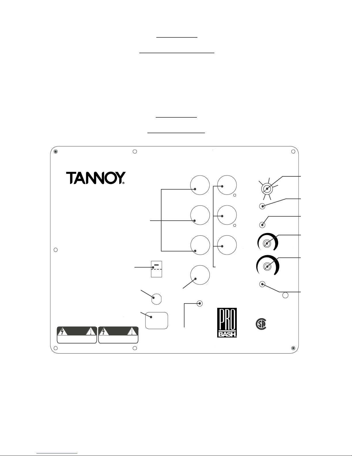
A): Left, Center, Right (LCR) inputs
Both the PS350 and PS350B have LCR inputs. The
PS350B is equipped with balanced XLR receptacles
wired in the following manner: Pin 1 = Ground, Pin 2 =
Positive (+) and Pin 3 = Negative (-). The PS350 incorporates an RCA receptacle and is wired to the following: Tip
= Signal and Sleeve = Ground. Note: It is extremely
important to read the entire manual since both models
have unique features that correspond to their inputs.
B): Left, Center, Right (LCR) outputs
These outputs have a fixed high pass filter point of 80 Hz
at 12 dB per octave. Each corresponds to its opposing
input, and they are actively isolated from one another.
With The PS350B, the LCR outputs can be made full
frequency by deactivating Bass Management, using the
LCR Remote By-Pass function (not available with the
PS350).
Page 5

C): Power Switch
The power switch is of a rocker style with international
markings on it indicating when the amplifier is ON or OFF.
When the switch is placed in the (-) position the amplifier
is ON. When the switch is placed in the (O) position the
amplifier is OFF. When the power switch is in the ON
position and the power cord is plugged into an AC source,
the LED located in the front of the subwoofer will illuminate Green indicating the amplifier is ON. Note: When signal is present the LED will turn from Green to Red indicating the amplifier is on and signal is present at the woofer.
D): Low Frequency Effect (LFE) input
Industry standards vary by format. Unfortunately, old formats do not match today’s format and there is still no
industry standard for LFE crossover points. The LFE input
on this subwoofer is selectable between a fixed low pass
filter point of 120 Hz at a rate of 12 dB per Octave, or an
"all pass" mode utilizing the full bandwidth of the amplifier.
This gives the optimum flexibility for all LFE program
information. The LFE fixed crossover will give added protection to the subwoofer by limiting its bandwidth without
compromising the program material, or by adding overlapping filtering, while the "all pass" mode gives a non-filtered input. Note: See LFE Crossover Mode.
E): Fuse
In the unlikely event of an amplifier failure, an AC protection fuse has been incorporated for safety. If the subwoofer does not turn on, unplug the power cord from the
AC source. Unscrew the fuse cap and check the fuse.
Note: If you are replacing the fuse, it MUST be replaced
with the same fuse rating or all safety certifications and
warranties will be voided.
F): AC Power
Make sure the power switch is in the OFF position (O)
and the male end of the cord is unplugged from an AC
source. Using the AC power cord that is enclosed in the
box, insert the female end of the cord into the IEC socket.
After the cord is inserted into the IEC socket, plug the
male end of the cord into an AC source. Special Note:
Make sure the AC source voltage matches the voltage
requirements information on the subwoofer amplifier
panel, if they do not, STOP, or damage will occur. AC
power requirements of the amplifier is 300 Watts.
G): LCR Remote Bypass - for model PS350B only
This feature gives you the ability to select Bass Management "in" or "out" by simply moving a switch. For operation, insert the supplied 1/8" (3.5 mm) plug into the
appropriate receptacle. By pressing the switch on the end
of the cable you will be deactivating the Bass
Management. When deactivating the Bass Management,
two operations are occurring simultaneously. One, the
LCR 80 Hz High Pass filters are by-passed making the
outputs full frequency. Two, the LCR signal is removed
from the subwoofer signal path. The only signal present
at the subwoofer will be from the LFE input. By depressing the switch again, you will reactivate the Bass
Management.
LCR Remote Bypass Switch
1/8” - 3.5 mm
Mono
For custom remote switches, follow schematic diagram.
H): LCR Variable Crossover
Adjusts the crossover point for the subwoofer. In part 6.a.
of this manual we suggest the option of using the subwoofer’s internal high pass filter network. In this system,
that high pass filter point is fixed at 12 dB/Octave at 80
Hz. The variable low pass filter has a range of 40 Hz to
150 Hz at a 24 dB/Octave slope, which allows you to
adjust the amount of overlap in the operating range of the
subwoofer by about half an Octave. As the subwoofer
level is adjusted relative to the main speakers, you will
find that you need to adjust the low pass filter point to
avoid having a bump or hole in the bass response at the
80 Hz crossover point. While this could be thought of as
a bass control of sorts, it is really there to help match the
performance of the main speakers, and help compensate
for the anomalies of the room in which it is placed. We
will talk more about these anomalies in the "Placement of
the Subwoofer," section 5.
Filter Response
29 Hz
-3 dB 20 Hz
36 dB/Oct.
80 Hz
Fixed H.P. 80 Hz
12 dB/Oct.
40 Hz - 150 Hz
L.P.
Variable
24 dB/Oct
150 Hz
I): One sub / Two sub switch
This switch only applies to the Center input. When in the
"One Sub" mode the signal path is at unity gain. This
means the signal level of the Center input has equal gain
to the Left and Right inputs. When in the "Two Sub"
mode, the Center input gain is reduced by 6 dB. The reason for this feature is to allow for the use of two subwoofers in a 5.1 system. When using two subwoofers in
a 5.1 bass management system with the shown system
setup (fig 5), it is easy to see why the "One Sub/Two
Sub" feature is needed. The left signal is connected to
the left sub and the right signal is connected to the right
sub, and both subs need the center signal. The problem
now, is that a 12 dB gain in energy is coming from the
subwoofer. To obtain unity gain through the LCR we must
reduce the level of the signal of the Center channel program material. This is obtained by selecting the "Two
Sub" switch position. This does not affect each individual
subwoofer’s mode of operation because there is only Left
or Right signal present at each unit respectively.
Page 6

J): LFE Crossover Mode Selection Switch
The "all pass" switch position can be used when experimenting with a discrete subwoofer channel arrangement.
Careful and thoughtful use of the controls are required to
achieve best results.
For most music and film production applications, it is
mandatory to run the L.F.E. sub information through an
outboard proprietary production DSP unit. Most program
material has already been coded to limit the LFE bandwidth from 30 Hz to either 80 Hz or 120 Hz. For this
situation, it may be a requirement that the subwoofer
being used have a linear frequency response up to 300
Hz. This can be achieved by switching the LFE
crossover mode switch to the "all pass" position, which
over-rides the LFE fixed "low pass" internal crossover filter. When no outboard DSP processor is mandated or if
you are unsure, it is wise to use the internal "low pass"
filter for added subwoofer protection. To operate the internal "low pass" crossover frequency feature, move the
switch to the "LFE low pass" position.
K): LFE Boost
This control offers the user the ability to boost the extreme
low frequency energy below 63 Hz up to a maximum level
of 6 dB in a linear shelf mode. The maximum boost is
obtained by turning the adjustment knob fully clockwise.
The boost is eliminated once the knob is returned to the
full counter-clockwise position. This feature is to enhance
extreme low frequencies for maximum effects. As with all
equalization, we advise its use in moderation.
L): Master Level Gain Control
Adjusts the level of the subwoofer without affecting the
signal level that goes to your main speaker amplifier.
Because the subwoofer has an integral crossover filter,
this will also act as a bass shelving control for your complete loudspeaker system. While it is tempting to turn up
the subwoofer, it is there to reproduce low frequencies
with less effort, and lower distortion than the main speakers can achieve. The most important thing is to maintain
a balanced audio spectrum.
M): Phase switch
Depending on the distance that your subwoofer is placed
from your main speakers, it may be necessary to reverse
the phase of the subwoofer. This is achieved by simply
moving the switch to the "180 degree" position. In most
cases, the main speakers will work best with the subwoofer
in the "0 degree" position. In any case, a flip of the switch
will allow for quick reference. The switch is in the correct
position for your set-up when the low frequency output is
greatest at and below the crossover point selected.
Section 5
Placement of the Subwoofer
The governing factor in bass response heard in any room
will be room modes. In addition, it is important to remember
that a corner position offers
the best chance of exciting
Example
3 Room Boundary
(2 Walls and 1 Floor = +6dB)
the most room modes
(diagonal, orthogonal and
axial), but this also
changes the loading on the
subwoofer which lifts the
bass frequencies up in
level. Placing the woofer in
a corner (two walls and a floor) gives you another 3 dB
more low frequency energy than the two boundary condition, for a total of 6 dB over the unit in the middle of the
floor. When setting things up the first time, you will need
to adjust the subwoofer level for various room positions
you try to keep the system balance the same. The point of
experimenting with subwoofer placement is to get the
bass response smooth and even, not just getting lots of
low frequency output.
If you’re using Tannoy main speakers, you may want to
consider experimenting using the closed-cell foam reflex
port plugs that were originally supplied in the speaker
packaging. This will help tighten up the mid bass (80 Hz+)
performance since we don’t need the ports to enhance
the bass below 80 Hz. This plug is a pressure fit, so it can
be removed at a later date if required. Here are some
additional tips that will help you get the best during set-up:
Experiment with the subwoofer features.
Make sure you’re not being impressed by more bass
instead of smooth bass.
Don’t rely on a one third Octave RTA (Real Time
Analyser) to look for accurate guidance on level adjustment, or for room mode response at any specific position.
It doesn’t have the time or the frequency capability. The
best way to listen is with a slow progression of low frequency notes. Are there drastic variations in the level of
notes? If they come out of the signal source at the same
level, you can be pretty sure that the problems are room
related. If one listening position seems to provide significant variations, try another position several feet away.
Because the wavelengths are quite long, it usually takes a
change of position equal to a good fraction of the wavelength to hear the difference.
You also want to strive for a large uniform listening
area. It doesn’t help to have a point in your listening
space be perfect, but have that point be so small that you
can’t get both ears in it at the same time. Every listening
situation will be different and we can’t offer any more specific guidance on positioning than experiment and listen to
material you trust.
A subwoofer is an excellent tool for finding new sources
of rattles and buzzes in the listening area. Because there
is a concentrated low frequency source involved, nearby
objects such as wall panels, equipment cover plates, and
other objects may rattle. For maximum performance, you
will want to track down each rattle or buzz and correct it at
the source of the problem.
Page 7

Section 6
Installation
With the AC power off, place the subwoofer in, or close to
its chosen final position, making sure that there is easy
access to the amplifier panel and controls. Plug the subwoofer into the wall outlet, preferably the same outlet, or
at least the same circuit as your main speaker amplifier.
Connect your signal source outputs to the input connectors of your subwoofer. Here is where there are two
choices:
a: (Recommended) Another set of cables can be used to
connect the outputs of the subwoofer to the L and R
inputs of the main speaker amplifier. Please, don•t use
cheap cables to connect the subwoofer. Buy quality components for your audio installations. It will pay off in the
final experience. Using this connection method allows
use of the subwoofer•s built-in high pass filter network to
provide smooth transition of frequencies between the
subwoofer and the main speaker system.
b: (Optional) You may choose to allow your main speaker
system to operate full bandwidth, in which case you will
not require the cables from the subwoofer outputs to the
main speaker amplifier inputs. Connect the subwoofer
from either the signal source "sub out" or LFE connector,
or from a discrete channel output within the audio system. This method does not require any wiring changes to
your current main speaker set-up, but does not use the
subwoofer•s high pass filter network. It may, or may not,
offer the best performance characteristics. Some experimentation will be required to achieve optimum results.
Ensure that your left and right channels have been connected correctly through the chosen signal chain. Turn
the gain control to minimum. Turn the subwoofer amplifier "On" and look for the green LED to show power present. Note that the unit features an auto on/off circuit,
which will turn the subwoofer off if there is no input signal
for more than two minutes (indicated by the green LED
turning to red). The sub will instantainiously turn on
again, (Indicated by the red LED turning green) as soon
as an input signal is received. Start your program material and adjust your main speakers to a normal listening
level. If you have high passed your main speakers, do
not be alarmed that they sound thinner, all the energy
below 80 Hz has been taken out of them for use by the
subwoofer. Now, adjust the subwoofer gain control until
you•re satisfied with a suitable level to match the main
speakers. If something isn•t working at this stage, you
can go ahead to the troubleshooting section (section 10),
get it running, and then come back to find out how to
make it work even better.
Section 7
Applications
a): One PS350/350B with powered receiver
1. Connect a cable from the receiver line level "LFE" or
"Sub Out" to the LFE input of the PS350B. The LFE
input has a fixed low pass crossover of 120 Hz. If a variable crossover is required, use the Left or Right input.
You can use the Center input but, make sure the 1 Sub/2
Sub switch is in the 1 Sub position or the signal will be by
attenuated by 6 dB. If you decide to use the variable
crossover, a good starting point is to between 80 Hz and
100 Hz.
2. Phase set to O deg. Note: Refer to Phase Switch
(4.M.) for further details.
3. Bass boost set to Min. Note: Refer to LFE Boost (4.K.)
for further details.
4. Set the Sub Level control on the PS350/PS350B to Min
initially.
figure 1
Left F ront
Left R ea r
In
Out
LF
LR
L
C enter
R eceiver
R F
C
C
1 S ub
2 S ubs
R ight F ront
LF E /
S ub Out
LFE
R R
R ight R ear
LFE
R
In
P S 350B
Page 8

b): One PS350/350B with preamp and 5
channel amp - no bass management
1. Connect the preamp line level "LFE" or "Sub Out" to
the LFE input of PS350/PS350B. The LFE input has a
fixed Low Pass crossover of 120 Hz. If a variable
crossover is required, use the Left or Right input. You
can use the Center input but, make sure the 1 Sub / 2
Sub switch is in the 1 Sub position or the signal will be
alternated by 6 dB. If you decide to use the variable
crossover, a good starting point is between 80 Hz and
100 Hz.
2. Phase set to 0 deg. Note: Refer to Phase Switch
(4.M.) for further details.
3. Bass boost set to Min. Note: Refer to LFE Boost (4.K.)
for further details.
4. Set the Sub Level on the PS350/PS350B to Min
initially.
c): One PS350B with preamp and 5 channel
amp - utilizing bass management
1. Connect the Left Front, Center, and Right Front outputs
of the preamp to the LCR inputs of the PS350B. The Left
Rear and Right Rear outputs of the preamp connect
directly to the 5 channel amplifier. The "LFE" or "Sub Out"
of the preamp connects to the LFE input of the PS350B.
Take the LCR outputs on the PS350B and connect them
to their corresponding channels on the 5 channel amplifier. If you decide to use the variable crossover, a good
starting point is between 80 Hz and 100 Hz.
2. Phase set to 0 deg. Note: Refer to Phase Switch (4.M.)
for further details.
3. Bass boost set to Min. Note: Refer to LFE Boost (4.K.)
for further details.
4. Set the Sub Level on the PS350B to Min initially.
figure 2
figure 3
Le ft F ront
In
Out
Le ft R ea r
Le ft F ront
Out
Le ft R ea r
P S 350B
L
1 S ub
2 S ubs
In
L
C enter
P reamp
C
LR
LF
LF E
C
R
In
In
LR
LF
Out
C enter
P reamp
C
LR
LF
LF E
C
R
In
1 S ub
P S350B
2 S ubs
C
R F
R F R R
R F R R
R R
LF E
LF E
F ive C hannel
Amp
R ight Front
R ight R ear
R ight Front
R ight R ear
Out
In
LR
C
LF
R F R R
Five C hannel
Amp
d): Two PS350/350B with preamp and 5
channel amp - no bass management
1. Using a "Y" cable, connect the preamp line level "LFE"
or "Sub Out" to the LFE inputs of PS350/PS350B•s 1 and
2, paralleling the two inputs together. The LFE input has a
fixed Low Pass crossover of 120 Hz. If a variable
crossover is required, use the Left or Right input. You can
use the Center input but, make sure the 1 Sub / 2 Sub
switch is in the 1 Sub position or the signal will be attenuated by 6 dB. If you decide to use the variable crossover,
a good starting point is between 80 Hz and 100 Hz.
2. Phase set to 0 deg. Note: Refer to Phase Switch (4.M.)
for further details.
3. Bass boost set to Min. Note: Refer to LFE Boost (4.K.)
for further details.
4. Set the Sub Level on the PS350/PS350B to Min
initially.
figure 4
Le ft F ront
In
Out
Le ft R ea r
C enter
P reamp
C
R F R R
C
R F RR
LF E
In
Out
L
1 S ub
2 S ubs
Five C hannel
Amp
LR
LF
LF E
C
L
1 S ub
2 S ubs
P S3 50
R
S ub 1
In
Pos itioned
Center Left
In
LR
LF
Out
R ight Front
P S3 50
LF E
C
R
S ub 2
In
Pos itioned
Center R ight
R ight R ear
Page 9

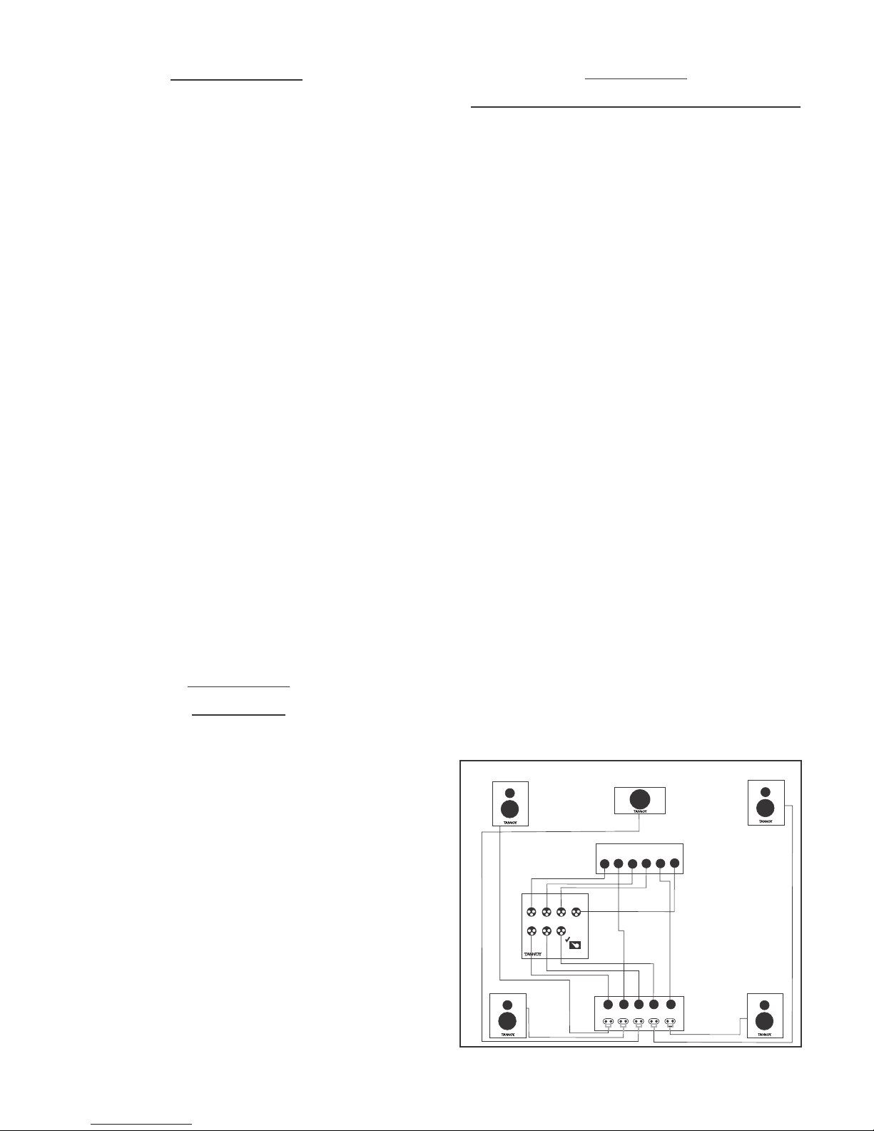
e): Two PS350B•s with preamp and 5
channel amp - utilizing bass management
1. Connect the Left Front and Center outputs of the preamp to the Left and Center inputs of the PS350B Sub 1.
Connect the Right Front and Center outputs of the preamp to the Center and Right inputs of the PS350B Sub 2.
Using a "Y" connector, connect the "LFE" or "Sub Out" of
the preamp to the LFE inputs of both PS350B•s. Connect
the Left and Center outputs on PS350B Sub 1, to their
corresponding channels on the 5 channel amplifier. Take
the Right output of Sub 2 and connect it to the corresponding channel in the 5 channels amp.
2. Set the LCR Variable Crossover. A good starting point
for the crossover is between 80 Hz and 100 Hz. Note:
Refer to LCR Variable Crossover (4.H.) for further details.
3. Phase set to 0 deg. Note: Refer to Phase Switch (4.M.)
for further details.
4. Bass boost set to Min. Note: Refer to LF Boost (4.K.)
for further details.
5. Place the 1 Sub/2 Sub switch in the •2 SubŽ position
on only one of the two PS350B•s.
6. Set the Sub Level on the PS350B to Min initially.
f): Stereo setup with one PS350/PS350B
utilizing internal filtering
1. Connect a cable from the signal source left output to the
PS350/PS350B Left input. Connect the Left subwoofer output to the power amplifier left input. Repeat for the right
channel.
figure 5
Le ft F ront
In
Out
Le ft R ea r
LEFT SPEAKER
C enter
P reamp
C
LR
LF
R F R R
R F RR
In
Out
OUTOUT
L
1 S ub
2 S ubs
Five C hannel
Amp
L
1 S ub
2 S ubs
In
Out
In
S ub 2
Pos itioned
Center Left
LR
LF
C
P S3 50
LF E
C
R
R ight Fro nt
P S3 50
LF E
C
R
S ub 2
In
Pos itioned
Center R ight
R ight R ear
Power Amp
IN
PS350/PS350B
IN OUT
L
C
R
IN
RIGHT SPEAKER
2. Phase set to 0 deg. Note: Refer to Phase Switch (4.M.)
for further details.
3. Bass boost to Min. Note: Refer to LFE Boost (4.K.) for
further details.
4. Set the Sub Level control on the PS350/PS350B to Min
initially.
g): Stereo Setup using two PS350/PS350B•s
utilizing internal filtering.
1. Connect a cable from the Signal Source Left output to the
Left input of the left side subwoofer. Connect the Left subwoofer output to the left input of the power amplifier. Repeat
for right channel.
2. Phase set to 0 deg. Note: Refer to Phase Switch (4.M.)
for further details.
3. Bass boost to Min. Note: Refer to LFE Boost (4.K.) for further details.
4. Set the Sub Level control on the PS350/PS350B to Min
initially.
figure 6
LEFT SPEAKER
figure 7
PS350/PS350B
IN OUT
L
C
R
OUT
OUT
Signal
Source
2 Channel
Power Amp
IN
OUT
Signal
Source
IN
OUT
RIGHTLEFT
Stereo setup
using one
PS350/PS350B
utilizing internal
filtering
RIGHT SPEAKER
PS350/PS350B
IN OUT
L
C
R
Stereo setup
using two
PS350/PS350B•s
utilizing internal
filtering
Page 10

Section 8
System Protection
Because accidents happen, this subwoofer system is
equipped with a protection limiter to prevent the amplifier
from operating in a sustained clipping condition, or at a
level that may cause damage to the woofer due to overexcursion. Because the subwoofer amplifier has a limiter,
there isn’t a clip light on the amplifier to indicate when it is
in distress. This protection system does allow the woofer
to deliver its rated peak SPL (Sound Pressure Level) of
114 dB without compromise. If a bass drum, or bass guitar doesn’t get any louder when you turn it up, and is
starting to sound squashed or flat, then you are probably
operating into the limiter. If you are finding that you are
operating into the limiter on a regular basis, you need to
consider two or more subwoofers within the system.
The subwoofer is a compact device, which allows the unit
to be easily placed where it can provide optimum performance. As part of the placement process, the performance can be fine tuned by adjusting the user controls provided. You only have to do this the first time you set your
system up. Once the balance is set between the subwoofer and the main speakers, the installation is complete.
The general rule for placement is between the left and
right channels in a two channel system, or under the center channel in a 5.1 or other surround system.
Section 9
Care of the Subwoofer
The subwoofer is finished with a vinyl covering that
resists most liquids, and can be cleaned with a damp
cloth, or a mild cleaner like WindexTM. Avoid wetting the
bass unit cone material during any cleaning effort. It
would be preferable that if you try to keep friends and
neighbors from placing beverages on the subwoofer.
Do not place the unit near a heater or forced air outlet, as
this may impair the ability of the internal amplifier to dissipate heat and may harm the finish. The unit requires adequate air volume or space around it to function properly.
Section 10
Troubleshooting
If you’re reading this, it is because of some unfulfilled
expectation for having sound come out of your new powered subwoofer. Let’s see if we can go over some of the
easy ways to remedy problems.
No sound comes out
A. Check that the unit actually powers up, look for the
green LED. If not, check that the AC outlet is live by using
a voltmeter, a circuit tester, or a lamp. If there is no power
at the wall, consult a qualified electrician.
B. If the AC outlet is live, and the amplifier is still not powered, double check that the power switch is in the ON
position.
C. If the unit is still not powered up, unplug the unit.
Remove and test the fuse on the rear control panel with a
continuity tester. If blown, replace with a new fuse of the
same specified value.
D. If the unit still refuses to power up, contact your dealer
or local Tannoy distributor.
If the unit is powered up and no audio comes out.
A. Check the Master Level Gain Control, to ensure that it
is in the position you expect it to be.
B. Make sure there is input signal at one of the LCR or
LFE inputs.
You are only getting signal through the LFE input.
A. Ensure that you are getting signal to the LCR inputs by
exchanging the LFE input with one of the LCR inputs.
B. If the Remote By-pass Cable is plugged into the
Remote By-pass jack, make sure the switch is in the Bass
Management position (-).
C. If the Remote By-pass Cable is plugged in and the
switch is in the (-) Bass Management position and no signal is coming out of the LCR inputs, disconnect it from the
amplifier panel. If audio passes through, the Remote Bypass Cable has a fault. If audio does not pass through
after disconnecting the Remote By-pass Cable, contact
your dealer or local Tannoy distributor.
Distorted sound comes out
A. Is the subwoofer bass the only distorted sound, or are
the main speakers distorted too? Check the signal quality
at the subwoofer input by connecting the signal cables
directly into the main speaker amplifier.
B. If the sound is still distorted with only the main speakers on, the problem is in the source. If the distortion is
eliminated by connecting around the subwoofer, test the
cables from the subwoofer to the main speaker amplifier.
C. If the subwoofer is the only distorted sound, determine
if it is distorted at any level setting. If it only happens at
high output levels, then it may be that you are overloading the input to the limiter. If you have eliminated the possibility of bass distortion in the source material, and confirmed that the unit is not being over-driven, contact your
dealer or local Tannoy distributor.
Page 11

LOUDSPEAKER SECTION
Section 11
Product Specifications
PS350 / PS350B
Frequency Response:
29 Hz - 300 Hz +/- 3 dB
Woofer diameter:
15” (381 mm) diameter
Low Frequency cutoff:
-3dB@29Hz,6thordertuningventedbox
(36 dB/Octave below 31 Hz)
AMPLIFIER SECTION
Input Connectors:
PS350B - L/R XLR fully balanced inputs
PS350 - L/R RCA inputs
Input Level:
Continuously variable input gain control
Low Pass Filter:
Continuously variable 40 Hz to 150 Hz,
24 dB/Octave
All Pass:
31Hz to 300Hz +/-3 dB
High Pass Filter:
Fixed at 80 Hz, 12 dB/Octave
High Pass output:
PS350B - L/R, unity gain XLR balanced
PS350 - L/R, unity gain RCA
High Pass output bandwidth:
80 Hz to 150 kHz +/- 3 dB
Maximum SPL:
116 dB peak SPL at 1 meter at limiter threshold
System dimensions:
20” high x 18 1/16” wide x 20” deep
508 mm high x 458 mm wide x 508 mm deep
System weight:
61 lbs - 27.7 kg
Amplifier type:
ProBASH technology featuring “High
™
Efficiency Linear Amplifier” circuit topology
Power rating:
350 Watts instantaneous peak (limiter
threshold)
Protection:
Threshold at onset of clipping
Power indicator:
Front mounted LED is greed in active
mode, “when signal is present or on initial
power up”. The green LED turns to red if
signal is not present for more than two minutes indicating stand-by mode. The sub
turns “auto on” when signal is re-introduced.
AC Power Requirement:
110/120 VAC 50/60 Hz
Power Consumption:
*At idle 15 Watts
*At rated power 280 Watts
No regular maintenance of the PS350/PS350B subwoofer is necessary.
All Tannoy professional loudspeaker products are covered by a 5 year warranty from the date of
purchase subject to the absence of misuse, overload or accidental damage.
Claims will not be considered if the serial number has been altered or removed.
Work under warranty should only be carried out by a Tannoy Professional dealer or service agent.
This warranty in no way affects your statutory rights.
For further information please contact your dealer or distributor in your area. If you cannot locate.
your distributor please contact Customer Services,
Tannoy North America Inc. at the address given below.
DO NOT SHIP ANY PRODUCT TO TANNOY WITHOUT PRIOR AUTHORIZATION
Our policy commits us to incorporating improvements to our products through continuous research
and development. Please confirm current specifications for critical applications with your supplier
Section 12
Warranty
Page 12

CAUTION
RISK OF ELECTRIC SHOCK
DO NOT OPEN
WARNING: SHOCK HAZARD, DO NOT OPEN.
AVIS: RIAQUE DE CHOC ELECTRIQUE - NE PAS OUVRIR.
CUIDADO: PELIGRO DE CHOQUE ELÉCTRICO - NO ABRIR
CAUTION: TO REDUCE THE RISK OF ELECTRIC SHOCK
DO NOT REMOVE COVER (OR BACK)
NO USER SERVICEABLE PARTS INSIDE
REFER SERVICING TO QUALIFIED PERSONNEL
THIS PRODUCT IS DESIGNED FOR 120-VOLT USE
ONLY! FOR DETAILED SAFETY PRECAUTIONS, PLEASE SEE
FOLLOWING PAGE IN THIS OWNER’S MANUAL FOR
“IMPORTANT SAFETY INSTRUCTION”.
The lightening flash with arrowhead symbol, within an equilateral triangle,
is intended to alert the user to the presence of uninsulated “dangerous
voltage” within the product’s enclusure that may be of sufficient magnitude
to constitue a risk of electrical shock to persons.
The exclamation point within an equilateral triangle is intended to alert the
user to the presence of important operating and maintenance (servicing)
!
!
“WARNING: SHOCK HAZARD - DO NOT OPEN. AVIS: RISQUE DE CHOC ELECTRIQUE - NE PAS OUVRIR” or
equivalent, together with the two graphical symbols - a lightning flash with arrow-point withing an equilateral triangle, an
exclamation point within an equilateral triangle, appears on the removable cover to gain access.
instructions in the literature accompanying the product.
L’éclair avec le symbole de la fléche, placé dans les limites d’un triangel
équilatéral est prévu pour avertír l’utilisateur de la présence de "lension
dangereuse" non isolée dans l’enceinte du produit qui pourrait érre d’une
importance suflisante pour présenter un risque d’électrocution aux personnes.
La point d’exclamation dans un triangel équilateral est prévu pour avertir
l’utilisateur de la présence d’instructions importantes pour les opérations
et l’entretien (service) dans les manuels fournis avec l’appareil.
ATTENTION: POUR EVITER LES CHOCS ELECTRIQUES, INTRODUIRE LA
LAME LA PLUS LARGE DE LA FICHE DANS LA BORNE CORRESPONDANTE DE LA PRISE ET POUSSER JUSQUAU FOND.
“CAUTION: TO PREVENT ELECTRICAL SHOCK, MATCH WIDE BLADE OF PLUG TO WIDE SLOT, FULLY INSERT” and
ATTENTION: POUR ÉVITER LES CHOCS ÉLECTRIQUES, INTRODUIRE LA LAME LAPLUS LARGE DE LA FICHE DANS
LA BORNE CORRESPONDANTE DE LAPRISE ET POUSSER JUSQU’AU FOND” or equivalent on a label attached on the
line cord, or the owner’s manual.
 Loading...