

Page 1

P S 1 1 0
P S 11 0 B
ACTIVE SUBWOOFER
REFERENCE
GUIDE
Tannoy North America Inc.
335 Gage Ave., Suite #1 Kitchener, Ontario Canada N2M 5E1
Tel:(519) 745-1158 Fax:(519) 745-2364 Toll Free Dealer Faxline:(800) 525-7081
e:mail: inquiries@tannoyna.com
Page 2
1.0 Introduction
The introduction will be short because we know that you want to
get this subwoofer up and running as soon as possible. But,
there are some important things you need to know before undertaking the unpacking and connecting process. This subwoofer
has features that you need to be familiar with prior to installation
to get the best performance.
2.0 Unpacking your Subwoofer
After opening the box, check the unit for shipping damage before
connecting to the AC supply and note if any damage relates to
any holes or crushing of the outer carton. There are no rattles or
loose pieces inside the subwoofer system by design, so if you
hear anything that sounds inappropriate for a powered subwoofer
while unpacking it, stop now, and check the carton for signs of
damage. If damage has occurred, contact your freight carrier
right away and have them register your damage claim.
3.0 Placement of the Subwoofer
The subwoofer is a compact device, which allows the unit to be
easily placed where it can provide optimum performance. As part
of the placement process, the performance can be fine-tuned by
adjusting the user controls provided. You only have to do this the
first time you set your system up. Once the balance is set
between the subwoofer and the main speakers, the installation is
complete. The general rule for placement is between the left and
right channels in a two channel system or under the center channel in a 5.1 or other surround system. If two subwoofers are
used, they are ideally positioned under, or close to the front left
and front right main
speakers.
The governing factor in
bass response heard at a
given location in any
room, are room modes. In
addition, it is important to
remember that a corner
position offers the best
chance of exciting the most room modes (diagonal, orthogonal,
and axial), but this also changes the loading on the subwoofer
which increases the amount of bass output. Placing the subwoofer in a corner (two walls and a floor) gives another 3 dB
more low frequency energy over the two-boundary location, for a
total of 6 dB over the unit in the middle of the floor. When you’re
setting things up the first time, adjust the subwoofer level for the
various room positions you try, keeping the overall system balance the same. The point of playing with the subwoofers room
placement is to get a smooth and even bass response, rather
than just getting lots of low frequency sound.
If you’re using Tannoy main speakers, you may want to consider
experimenting, using the closed cell reflex port foam plugs that
were originally included in the speaker packaging. This will help
tighten up the mid bass (80 Hz+) performance, since we don’t
need the ports to enhance the bass below 80 Hz. This plug is a
pressure fit, so it can be removed at a later date if required. Here
are some additional tips that will help you get the best during setup:
Experiment with the subwoofer features
Make sure you’re not being impressed with more bass instead
of smooth bass
Don’t rely on a one third Octave RTA (Real Time Analyzer) to
look for accurate guidance on level adjustment, or for room mode
response at any specific position. It doesn’t have the time or frequency capability. The best way to listen is with a progression of
low frequency notes. Are there drastic variations in the level of
those notes? If they come out of the signal source at the same
level, you can be sure that any problems are room related. If one
listening position seems to provide significant variations, try
another position several feet away. Because the wavelength of
bass frequencies is quite long, it usually takes a change of position equal to a good fraction of the wavelength to hear the difference.
You also want to strive for a large listening area. It doesn’t help
to have a point in your listening space be perfect, but have that
point be so small that you can’t get both ears into it at the same
time. Every listening situation will be different, and we can’t offer
more specific guidance on positioning than experiment and listen
to material you trust.
A subwoofer is an excellent tool for finding new sources of rattles
and buzzes in the listening area. Because there is a concentrated
low frequency source involved, nearby objects, such as wall panels,
equipment cover plates, and other objects may become excited and
pollute your systems performance. You need to track down each rattle and buzz and correct it at the source of the problem.
4.0 Installation
Sit the subwoofer in, or close to, where you believe its final position will be. Make sure you have easy access to the amplifier
panel and controls. Plug the subwoofer into a wall outlet, preferably the same outlet, or at least the same circuit as your main
speaker amplifier. Connect the signal source outputs to the input
connectors of your subwoofer. Here is where you have two choices:
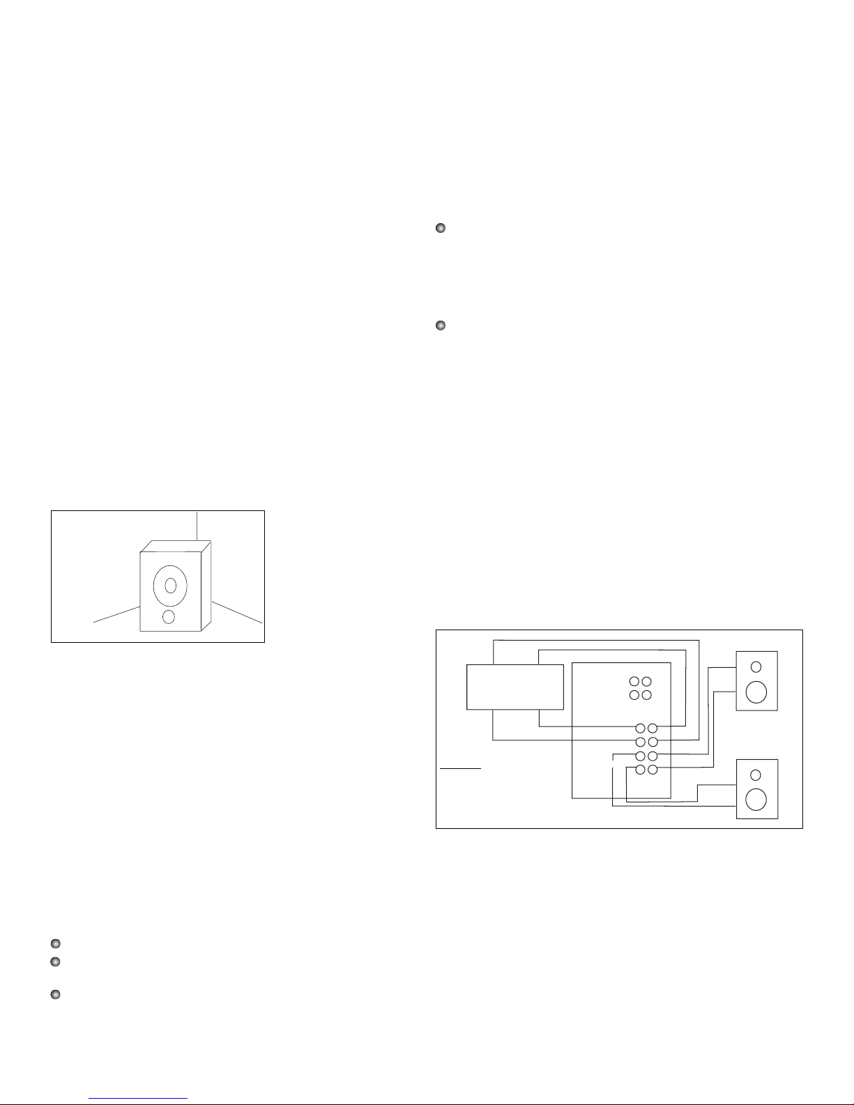
Note: For the PS110 version the following options also apply to
using the speaker level wiring option. However, speaker level
needs to be fed to the subwoofer from a two channel amplifier,
not a line level signal from a signal source. The speaker wires on
the subwoofer output side will go directly to the main speakers’
inputs, not the main speakers’ amplifier (fig. 1).
a: (Recommended) Another set of cables can be used to connect
the subwoofer outputs to the L and R inputs of the main speaker
amplifier. Please, don’t use cheap cables to connect the subwoofer. Buy quality components for your audio installation. It will
pay off in the final experience. Using this connection method
allows use of the subwoofers built-in high pass filter network to
provide smooth transition of frequencies between the subwoofer
and the main speaker system (PS110 fig. 2, PS110B fig. 3).
Example
3 Room Boundary
(2 Walls and 1 Floor = +6 dB)
Figure 1
Speaker level setup using
internal high pass filter.
Right
Speaker
-
Right
Speaker
+
Left
Speaker
+
Left
Speaker
-
AMPLIFIER
+
+
Speaker Level IN
High Pass OUT
IN
OUT
LEFT
RIGHT
RIGHT
LEFT
+
-
-
+
-
Right Speaker Out
Left Speaker Out
-
PS110
Page 3

b: (Optional) You may choose to allow the main speaker systems
to operate full bandwidth, in which case you will not require the
cables from the subwoofer outputs to the main speaker amplifier
inputs. This approach does not high pass your main speakers
and may or may not offer the best performance characteristics.
Some experimentation will be required to achieve optimum
results. (PS110 fig. 4, PS110B fig 5).
Ensure that your left and right channels have been connected
correctly through the chosen signal chain. Turn the gain control
to minimum. Turn the subwoofer amplifier "On" and verify the
LED is illuminated, indicating power is present. Note that the unit
features an auto on/off circuit, which will turn the subwoofer off if
there is no input signal for more than two minutes (indicated by
the green LED turning to red). The sub will instantaneously turn
on again, (indicated by the red LED turning green) as soon as an
input signal is received. Start your program material and adjust
your main speakers to the normal listening level. If you have high
passed the main speakers, do not be alarmed that they sound
thinner, all the energy below 80 Hz out of them for use by the subwoofer.
Now, adjust the subwoofer gain control until you’re satisfied with
a suitable level to match the main speakers. If something isn’t
working at this stage, you can go ahead to the troubleshooting
section, get things running, and then come back to find out how
to make it work even better.
5.0 Adjustable controls
a: Sub Level (Gain Control)
Adjusts the level of the subwoofer without affecting the signal
level that goes to your main speaker amplifier. Because the subwoofer has an integral crossover filter, this will also act as a bass
shelving control for your complete loudspeaker system. While it is
tempting to turn the subwoofer levels up, it is there to reproduce
low frequencies with less effort, and lower distortion, than the
main speakers alone can achieve. The most important thing is to
maintain a balanced audio spectrum.
b: Crossover Frequency (Variable Low Pass Filter)
This adjusts the crossover point for the subwoofer. In this system, that high pass filter point is fixed at 12 dB / Octave at 80 Hz.
The variable low pass filter has a range of 40 Hz to 150 Hz at a
24 dB / Octave slope, which allows you to adjust the amount of
overlap in the operating range of the subwoofer by about half an
octave. As you adjust the level of the subwoofer relative to the
main speakers, you will find that you need to adjust the low pass
filter point to avoid having a bump or hole in the bass response
at the 80 Hz crossover point. While you could think of this as a
bass control of sorts, it’s really there to help match the performance of your main speakers.
c: Crossover Mode
Overrides the subwoofer internal low pass filter in the "all pass"
position. The "all pass" switch position can be used when experimenting with a discrete subwoofer channel arrangement. Careful
and thoughtful use of the controls are required to achieve the
best results.
For certain music and film production applications, it is mandatory to run the L.F.E. (Low Frequency Effects) information through
an outboard proprietary production DSP unit. In this situation, it
is a requirement that the subwoofer being used has a linear frequency response up to 300 Hz. This can be achieved by switching the crossover mode switch to the "all pass" position, which
overrides the subwoofers internal low pass filter. When no outboard DSP processor is mandated, the internal low pass filter
must be engaged, (switch in the low pass mode) to operate the
internal low pass crossover frequency feature.
d: LF Boost
This control offers the user the ability to boost the extreme low
frequency energy below 63 Hz, up to a maximum level of 4 dB in
a linear shelf mode. The maximum boost is obtained by turning
the adjustment knob fully clockwise. The boost is eliminated once
the knob is returned to the full counter-clockwise position. This
feature is to enhance extreme low frequencies for maximum
effects. As with all equalization, we advise its use in moderation.
e: Phase Switch
Depending on the distance that your subwoofer is placed from your
main speakers, it may be necessary to reverse the phase of the
subwoofer. This is achieved by simply moving the switch to the
180 degree position. In most cases, you will find that the main
speakers will work best in the 0 degree position. In any case, trying
both positions of the switch will allow for quick reference. The switch
is in the correct position for your setup when the low frequency
output is greatest at, and below, the crossover point selected.
Figure 2
Line level
setup for
PS110 suing
internal high
pass filter.
Figure 3
Line level setup for
PS110B using internal
high pass filter.
Figure 4
Setup for discrete subwoofer
channel for PS110
figure 5
Setup for
discrete
subwoofer
channel for
PS110B
Left
Out
SURROUND PROCESSOR
A/V RECEIVER
OR
Right
Right
Out
In
Left
In
AMPLIFIER
Right
Left
Out
Out
Right Speaker
In
Speaker Level IN
Speaker Level OUT
Out
Left
Right
RightLeft
+
-
-
+
Left Speaker
PS110
L
Out
Signal Source
Out
High Pass
Output
Input
R
AMPLIFIER
OUT
OUT
IN
IN
Main
Speakers
PS110
IN
SURROUNG PROCESSOR
Sub Out
A/V RECEIVER
OR
Speaker Level IN
Speaker Level OUT
OUT
Left
Right
Left
Right
+
-
-
+
PS110
Signal Source
Out
In
Main Speaker
Amplifier
Out
Out
Out
In
Out
Input
High Pass
Output
PS110
LR
Main
Speakers
Page 4

6.0 Protection System
Because accidents happen, this subwoofer system is equipped
with a protection limiter to prevent the amplifier from operating in
a sustained clipping condition, or at a level that may cause damage to the low frequency drive unit due to over-excursion.
Because the subwoofer amplifier has a limiter, there isn’t a clip
light on the amplifier to indicate when it is in distress. This protection system allows the woofer to deliver its rated peak SPL of
110 dB without compromise. If a bass drum or bass guitar doesn’t
get any louder when you turn it up, and is starting to sound
squashed or flat, then you are probably operating into the limiter.
If you find that you are running into the limiter on a regular basis,
you need to consider two or more subwoofers within the system.
7.0 Care of the Subwoofer
The subwoofer is finished with a vinyl covering that resists most
common liquids, and can be cleaned with a damp cloth, or mild
cleaner like Windex
©. Avoid wetting the drive unit cone material
during any cleaning effort. It would be preferable if you try to
keep friends and neighbors from placing beverages on the subwoofer.
Do not place the unit near a heater or forced air outlet, as this
may impair the ability of the internal amplifier to dissipate heat
and may harm the finish. The unit requires adequate air volume
or space around it.
8.0 Troubleshooting
If you’re reading this, it is because no sound is coming out of
your new powered subwoofer. Here are some of the easy ways
to remedy problems.
a: No sound comes out
Check that the subwoofer powers up by looking for the illuminated LED. If the LED is not illuminated, check that the AC outlet is
live by using a voltmeter, a circuit tester, or a lamp. If there is no
power, consult a qualified electrician.
If the AC outlet is live, and the amplifier is still not powered,
check that the power switch is in the "On" position. If the unit is
still not powered up, unplug the unit, remove and test the fuse on
the rear control panel with a continuity tester. If blown, replace
with a new fuse of the same specified value. If the unit still refuses
to power up, call your dealer or local Tannoy distributor.
If the unit is powered up, check the level control to ensure that it is
not in the minimum position. Check that the signal from the
source components is getting as far as the subwoofer. If there is
signal present on the cables at the subwoofer inputs, the power is
on, and the level control is up and no sound comes out, then this
is a significant problem and should be referred to your dealer or
local Tannoy distributor.
b: Distorted sound comes out
Is the subwoofer bass the only distorted sound, or are the main
speakers distorted as well? Check the signal quality at the subwoofer input by connecting these cables directly into the main
speaker amplifier inputs. If the sound is still distorted with only
the main speakers on, the problem is in the source. If missing out
the subwoofer eliminates the distortion, check the cables from
the subwoofer to the main speaker amplifier. If the subwoofer is
the only distorted sound, determine if it is distorted at any level
setting. If it only happens at high output levels, then it may be
that you are driving the system too hard. Extremely high input
levels may overload the input to the limiter. If you have eliminated
the possibility of bass distortion in the source material, and confirmed that the unit is not being over driven, then this too is a significant problem and should be referred to your dealer or local
Tannoy distributor.
9.0 Specifications
LOUDSPEAKER SECTION
Frequency Response: -3 dB 31 Hz -150 Hz (-10 dB @ 21 Hz)
Bass unit diameter: 10" - 254 mm
Low Frequency cutoff: -3 dB @ 31 Hz, 6th order tuning
vented box (36 dB / Octave below 31 Hz)
Maximum SPL: 110 dB peak SPL @ 1 meter at limiter
threshold
System dimensions: H 17.5"- 445 mm x
W 11 5/16" - 287 mm D x 16.5" - 419 mm
System weight: 33 Lbs -14.5 Kg
AMPLIFIER SECTION
Input Connectors:
PS110B: L/R XLR balanced inputs, 10 kOhm
PS110: L/R RCA, speaker level option
Input Level: Continuously variable input gain control
Low Pass Filter: Continuously variable 40 Hz - 150 Hz,
24 dB/Octave
All Pass: 31 Hz - 300 Hz +3 dB
High Pass Filter: Fixed at 80 Hz, 12 dB / Octave
High Pass output:
PS110B: L/R, unity gain XLR balanced
PS110: L/R RCA, speaker level option
High Pass output Bandwidth: 80 Hz - 150 kHz -3 dB
Amplifier type: Mosfet outputs
Power rating: 110 Watts RMS
Protection: Limiter threshold at onset of clipping
Power indicator: Front mounted green LED in active
mode, "when signal is present or on initial power up".
Green LED turns to red if signal is not present for more
than two minutes indicating stand-by mode. The sub turns
"auto on" when signal is re-introduced.
AC Power Requirement: 110/120 VAC 50/60 Hz or
220/240 VAC 50/60 Hz
Power Consumption:
16 Watts at idle
150 Watts at rated power
Tannoy North America Inc.
335 Gage Ave., Suite #1 Kitchener, ON Canada N2M 5E1
Tel:(519)745-1158 Fax:(519)745-2364
Toll Free Dealer Faxline:(800)525-7081
e-mail: inquiries@tgina.com
www.tannoy.com
Part No. 5000.1001
 Loading...