

Tannoy POWER V6, POWER V8, POWER V12, POWER V12HP, POWER V15 Owner's Manual
...
POWER V6, POWER V8, POWER V12, POWER V12HP, POWER V15,
POWER VS10BP & POWER VS15BP
Owners Manual

2
1.0: IMPORTANT SAFETY INSTRUCTIONS
2.0: INTRODUCTION
3.0: THE BASICS 3.1 Unpacking and visual checks
3.2 Preliminary recommendation
4.0: INTERFACE PANEL
5.0: OPERATION 5.1: AC power requirements
5.2 Cooling
5.3 LED functions
5.4 Limiters
5.5 Audio Connections
6.0: EQUALISATION
7.0: ARRAYING
8.0 DIMENSIONS
9.0: TECHNICAL SPECIFICATIONS
10.0: RIGGING 10.1 : SECUR ET - V6Y yoke bracket
10.2 : SECUR ET - V8Y yoke bracket
10.3 : SECUR ET - VMY yoke bracket
10.4 : SECUR ET - V15Y & V12Y
10.5 : SECUR ET - VMB wall mounting bracket
10.6 : SECUR ET - VEB eyebolt
10.7 : SECUR ET - VTH pole mount
10.8 : SECUR ET - VCS ceiling saddle
10.9 : SECUR ET - VPC pole clamp
11.0: SERVICE PARTS & ACCESSORIES
12.0: WARRANTY
13.0: DECLARATION OF CONFORMITY
14.0: NOTES
CONTENTS

3
1.0: IMPORTANT SAFETY INSTRUCTIONS
IMPORTANT SAFETY INSTRUCTIONS
1 Read these instructions.
2 Keep these instructions.
3 Heed all warnings.
4 Follow all instructions.
5 Do not use this apparatus near water.
6 Clean only with dry cloth.
7 Do not block any ventilation openings. Install in accordance with the manufacturer's instructions.
8 Do not install near any heat sources such as radiators, heat registers, stoves or other apparatus (including amplifiers)
that produce heat.
9 Do not defeat the safety purpose of the polarized or grounding type plug. A polarized plug has two blades with one
wider than the other. A grounding type plug had two blades and a third grounding prong. The wide blade or the third
prong are provided for your safety. If the provided plug does not fit into your outlet, consult an electrician for replacement
of the obsolete outlet.
10 Protect the power cord from being walked on or pinched particularly at plugs, convenience receptacles and the point
where they exit from the apparatus.
11 Only use attachments / accessories specified by the manufacturer.
12 Use only with the cart, tripod, bracket or table specified by the manufacturer, or sold with the apparatus. When a cart
is used, use caution when moving the cart / apparatus combination to avoid injury from tip-over.
13 Unplug this apparatus during lightening storms or when unused for long periods of time.
14 Refer all servicing to qualified service personnel. Service is required when the apparatus has been damaged in any
way, such as power-supply cord or plug damaged, liquid has been spilled or objects have fallen into the apparatus,
this apparatus has been exposed to rain or moisture, does not operate normally, or has been dropped.
SAFETY WARNING
Permanent disconnection from the mains supply is to be achieved by removing the supplied cord connector from the back of
the unit.
SAFETY WARNING
Do not remove any covers, loosen any fixings or allow items to enter any aperture.
SAFETY WARNING
Objects filled with liquids should not be placed on this apparatus.
SAFETY WARNING
Replace the mains fuse only with the same T10A HBC type supplied by Tannoy under part number 34610919
SAFETY WARNING
The rear heatsink on this product gets hot. Avoid direct skin contact during operation and for at least 5 minutes after power
has been isolated.
AVERTISSEMENT DE SECURITE
Pour déconnecter l'appareil de l'alimentation principale de façon permanente, débranchez le connecteur du câble fourni à
l'arrière de l'appareil.
AVERTISSEMENT DE SECURITE
Ne retirez pas les couvercles, ne desserrez pas les fixations et ne laissez aucune pièce s'introduire dans les ouvertures.
AVERTISSEMENT DE SECURITE
Ne placez pas d'objets contenant du liquide à proximité de l'appareil.
AVERTISSEMENT DE SECURITE
Ne remplacez le fusible de réseau principal que par un fusible T10A HBC du même type fourni par Tannoy sous la référence
34610919.
AVERTISSEMENT DE SECURITE
Le radiateur arrière de cet appareil devient chaud. Evitez tout contact direct avec la peau pendant le fonctionnement et au
moins 5 minutes après la mise hors tension de l'appareil.
The lightning flash with an arrowhead symbol within an
equilateral triangle, is intended to alert the user to the
presence of uninsulated “dangerous voltage” within the
product’s enclosure that may be of sufficient magnitude
to constitute a risk of electric shock to persons.
The exclamation point within an equilateral triangle is
intended to alert the user to the presence of important
operating and maintenance (servicing) instructions in the
literature accompanying the product.

4
INSTALLATION INSTRUCTIONS
1 THIS PRODUCT MUST BE EARTHED. Use only a flexible cable or cord provided with a green or green and yellow core
which must be connected to the protective earthing terminal of the detachable Neutrik 'Powercon' type NEC3FCA
connector (Tannoy part number 3461 0919 as supplied with the equipment. The other end of the green or green and
yellow conductor must be connected to the earthing pin of a suitable mains plug or the earthing terminal of the installation.
The cord must be of maximum length 7.5 meters, rated SJ, SJT, or SJE, 10A minimum and be marked VW-1.
2 The electrical power connection to this product is only to be made via a detachable Neutrik 'Powercon' type NEC3FCA
connector (Tannoy part number 3461 0919) as supplied with the equipment. Wiring to this connector must only be made
by suitably qualified personnel and must comply with all local requirements.
3 Do not install this equipment in an enclosed space. Do not limit free ventilation and movement of air around the back
panel. Ensure that there is at least 100mm (4") of space around all sides of the product for ventilation.
4 Only use attachments and accessories approved by or specified by Tannoy.
FOR CUSTOMERS IN EUROPE
This product complies with both the LVD (electrical safety) 73/23/EEC and EMC (electromagnetic compatibility) 89/336/EEC
directives issues by the commission of the European community.
Compliance with these directives implies conformity with the following European standards:
EN60065 Product safety
EN55103-1 EMC emissions
EN55103-2 EMC immunity
This product is intended for the following electromagnetic environments: E2; E3 & E4. Environment E1 (domestic) is specifically
excluded.
FOR CUSTOMERS IN THE USA & CANADA
This product has been tested for electrical safety and complies with:
UL60065 7th edition
CA /CSA C22.2 No.60065-03
EMC
This equipment has been designed to comply with the limits for a Class A digital device, pursuant to part 15 of the FCC Rules.
These limits are designed to provide reasonable protection against harmful interference when the equipment is operated in a
commercial environment.
Industry Canada Class A emission compliance statement: This Class B digital apparatus complies with Canadian ICES-003.
Avis de conformite' a' la re'glementation d'Industrie Canada. Cet appareil nume'rique de classe A est conforme a' la norme
ICES-003.
2.0: INTRODUCTION
Power V™ is a range of active sound reinforcement loudspeakers equipped with the Tannoy Dual Concentric™, point source,
constant directivity drive unit technology. By combining the ‘Dual’ with a sophisticated amplifier package integrated within the
speaker cabinet, Power V™ is aimed at installation applications where uncompromised sound quality and flexibility is essential.
In order to satisfy a wide scope of fixed or on the road sound reinforcement applications there are five full range models and
two subwoofers in the Power V™ range; Power V6, Power V8, Power V12, Power V12HP and Power V15; along with the
subwoofers - Power VS10 BP and Power VS15 BP.
The location of the high frequency drive unit, in the throat of the low frequency driver, ensures that the driver delivers constant
directivity and unparalleled linearity from a true point source.
The spherical wave front delivered presents an even dispersion in both horizontal and vertical planes, providing exceptional
off-axis performance and an even response throughout a wide listening area. Overcoming the time alignment problems inherent
in a discretespeaker design the constant directivity characteristics of the ‘Dual’ exhibits better harmonic alignment, delivering
a more natural sound with superb tonal balance and greater intelligibility. This highly integrated driver design approach provides
a constant time delay over the frequency spectrum ensuring enhanced transient performance and sound quality.
5
All Power V™ loudspeakers are equipped with highly efficient, flexible and reliable Class D power amplification incorporating
switching power supplies. Optimally matched power supplies and power amplifier sections minimises noise and enhances
stability. Little is required in the way of heat sinking so the only surface area needed for cooling is the small control panel on
the rear of the cabinet; therefore, even when driven at very high power levels no fans are required, so the system runs quietly
and is not prone to internal dust contamination.
When used as a stand-alone speaker there is, on the rear panel of the full range Power V™ models, a mode switch for ‘Full
Range’.Alternatively the ‘High Pass’ position provides increased headroom for when the unit is used within close proximity to
a boundary and, in a simple setup, allows crossover to a subwoofer without the need for an external crossover.
LED’s on the rear panel indicate, signal pressence, signal activity, and power. Two low pass settings on the subwoofer amplifiers
fully optimise integration with the full range units.
Recessed carrying handles aid manoeuvrability and multiple flying points are incorporated to provide a quick and secure flying
system. Tannoy’s proprietary Secur-ET™ modular mounting hardware provides the Power V™ range with multiple hanging
options such as wall mount brackets, yoke fittings, ceiling saddles, pole clamps, pole mounts and eyebolts.
3.0: UNPACKING AND VISUAL CHECKS
Every Tannoy PowerV™ product is carefully tested and inspected before being packaged and leaving the factory. After
unpacking your loudspeaker, please inspect for any exterior physical damage, and save the carton and any relevant packaging
materials in case the loudspeaker again requires packing and shipping. In the event that damage has been sustained in transit
notify your dealer immediately.
3.1: PRELIMINARY RECOMMENDATION
A word of warning on high sound levels - these speakers are capable of generating high output levels over sustained periods
of time and such levels, over 95dBspl for 8 hours per day, can eventually cause permanent hearing loss. Since Tannoy
loudspeakers have a natural-sounding flat frequency response and low distortion, it's possible not to be aware just how high
the sound level is high while working with them.
For continuous exposure we recommend the occasional use of a sound level meter. This should be capable of integrating the
sound level over a period of exposure according to noise control standards and used just to check that noise levels are always
within safety limits.
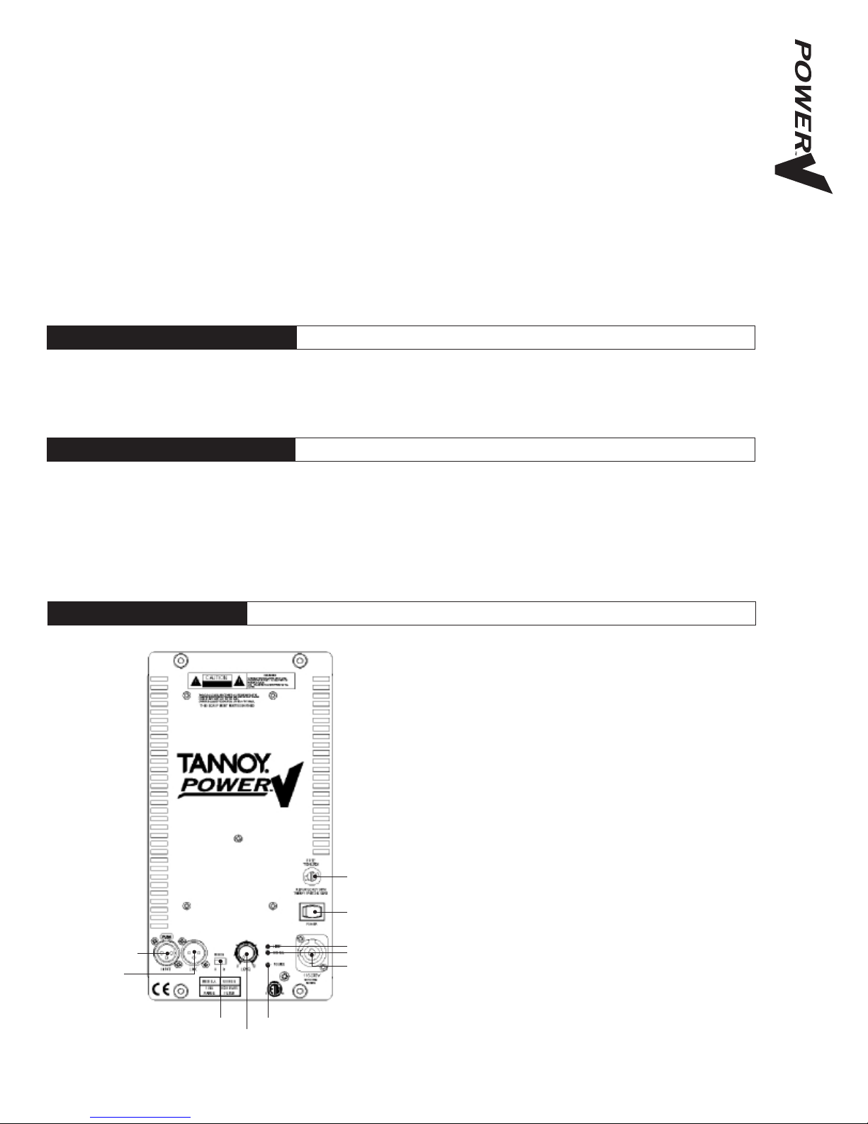
4.0: INTERFACE PANEL
XLR FEMALE AUDIO INPUT - This is a lockable XLR line input
socket for connection to the audio source. Fully balanced.
Pin 2 Hot (+), Pin 3 Cold (+), & Pin 1 Ground.
XLR MALE AUDIO LINK - This is a lockable XLR line output socket
to link additional speakers. Fully Balanced.
Pin 2 Hot (+), Pin 3 Cold (+), & Pin 1 Ground.
ROCKER POWER SWITCH - Turns AC power on to the unit (100V
- 240V)
FUSE HOLDER - Replace only with 10A 230V anti-surge fuse.
AC MAINS CONNECOR - Neutrik Powercon mains connector
(supplied)
SIGNAL PRESENT LED - LED indicates when signal is being been
received by the speaker.
LIMIT LED - LED indicates when the integral limiter is functioning
to protect the speaker.
POWER LED - LED indicates when power has been applied to the
speaker.
MODE SWITCH - Switch allows the speaker to be toggled between
two modes;
• The subwoofers can either have an 80Hz or 110Hz low-pass
filter (LPF) filter activated.
• The full range speakers can either be run full range or have
a fixed high-pass filter (HPF) activated.
LEVEL CONTROL - Control allows adjustment of the speaker volume.
•
•
•
•
•
•
•
•
•
•
XLR FEMALE AUDIO INPUT
XLR MALE AUDIO LINK
FUSE HOLDER
NEUTRIK POWERCON
LOCKING MAINS CONNECOR
SIGNAL LED
LIMIT LED
POWER LEDMODE SWITCH
LEVEL CONTROL
ROCKER POWER SWITCH
6
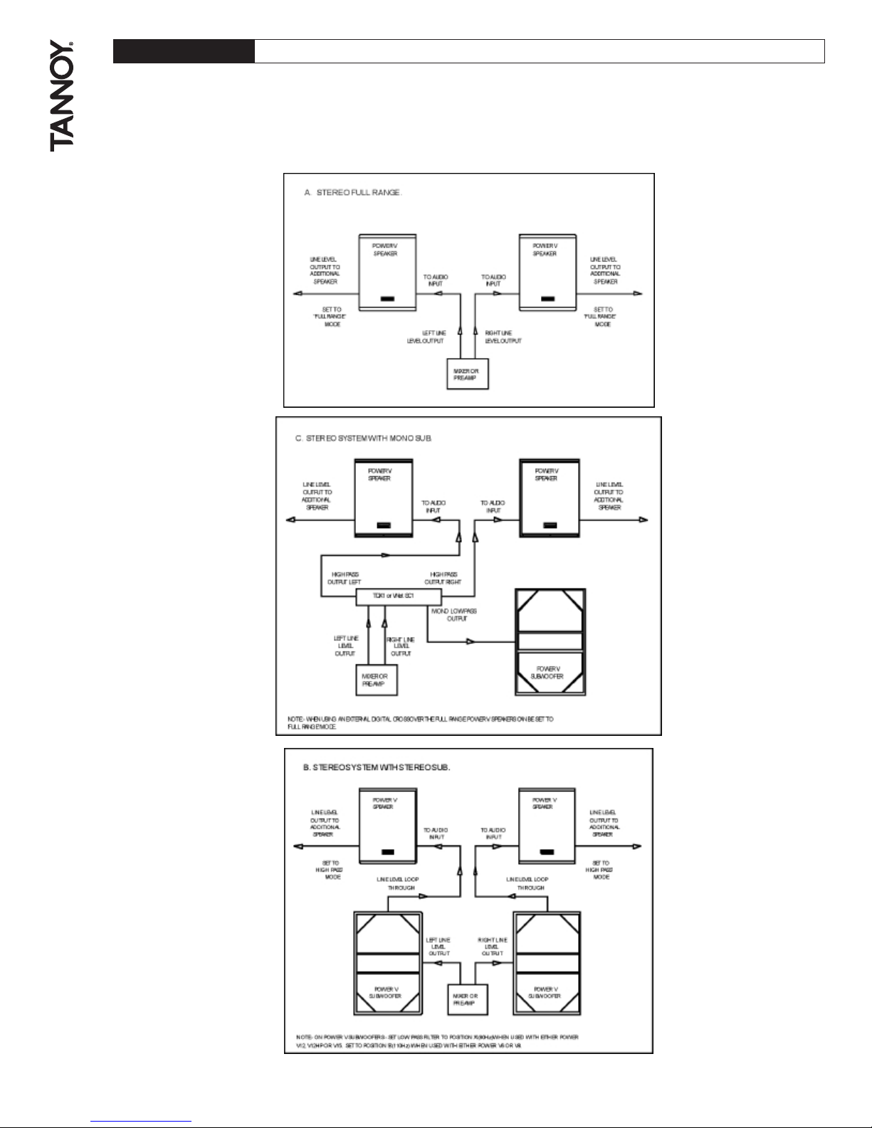
5.0: OPERATION
The Power V™ range of products are integrated designs which include system specific EQ and protection circuitry, without
the need for external amplification. For room equalization, delay and other commissioning or setup functions, we recommend
you use a Vnet SC1 or TDX1 Digital Controller.
Below are example setups

7
5.1: AC POWER REQUIREMENTS
PowerV™ products are equipped with Neutrik Powercon™ mains connectors which mate with the Neutrik NAC3FCA Cable
connector, quick lock with a securing lever for power-in. This AC mains connector is supplied with each PowerV™ product.
The amplifier operates between the ranges of 100 to 240 Volts; the auto ranging power supply detects the mains voltage
automatically and configures accordingly. Replace the mains fuse only with the same T10A HBC type. It is necesary to have
power local to eacvh speaker, as it is not possible to daisy chain the AC power connections.
5.2 COOLING
Do not install this equipment in an enclosed space. Do not limit free ventilation and movement of air around the back panel.
Ensure that there is at least 100mm (4") of space around all sides of the product for ventilation. An efficient switch mode power
supply has less weight, less current draw and more efficient mechanical cooling; meaning that no fans are required.
5.3 LED FUNCTIONS
Power LED – When AC mains is connected to he speaker and the power switch is turned on the blue lower LED will illuminate.
Signal LED – The Green LED indicates that a useable signal is present at the input.
Limit LED - When illuminated this indicates that the system is approaching clipping.
An occasional flicker of the red LED on the loudest peaks is acceptable. If this LED remains red for more than the duration of
brief dynamic peaks, or lights continuously then the system is being overdriven.
If the red LED illuminates excessively:
• Reduce the input level (see interface panel)
• Reduce the output level of the mixer, or other source to the speaker.
5.5: AUDIO CONNECTIONS
Audio Connections
The signal input & link connectors are fully balanced. SIGNAL XLR CONNECTOR
When connecting a balanced signal be sure to wire Hot (+) Pin 2
to the following standard:- Cold (-) Pin 3
Shield (GND) Pin 1
In a standard balanced interconnection there are two signal conductors and a shield. The shield is normally referenced to
ground at one or both ends. Many times the shield is lifted at one end, usually at the input to eliminate "ground loops" or noise.
The problem with this approach is that while it may reduce hum, the shields act as radio antennas and pickup radio frequency
interference from the environment.
Multiple enclosures may be driven from a single audio source; simply plug the signal source output into the first XLR input
socket, and patch that speakers XLR link to the next speakers XLR input socket & so on.
5.4 LIMITERS
The limiters are carefully set-up to preserve the loudspeakers dynamic headroom by allowing short term transients to pass;
audible degradation in sound will only become apparent when the limit indication is on constantly. The limiting functions will
protect the amplifier from long term overheating by attenuating the driving voltage to the drive units. If used irresponsibly
(constant hard clipping) sound quality will be compromised. In extreme cases drive units may also be damaged.
6.0: EQUALISATION
PowerV™ loudspeakers are designed to need no equalisation or correction to overcome system limitations. As a result, they
will only need equalisation to compensate for difficult acoustic environments.
Over equalisation can reduce system headroom, and introduce phase distortion resulting in greater problems than cures. If
equalisation is required then it should be applied gently and smoothly. PowerV™ full range loudspeakers are point source,
phase coherent designs and violent equalisation will be detrimental to the overall sound quality. When a loudspeaker is used
in close proximity to another, comb filtering effects can create coverage problems; comb filtering creates an uneven frequency
response across the coverage area due to constructive and destructive interference effects between the sources. The amount
of comb filtering is affected by the spacing of the relative sound sources. Minimising this effect cannot be cured by equalisation
(see the following section for more details).
8
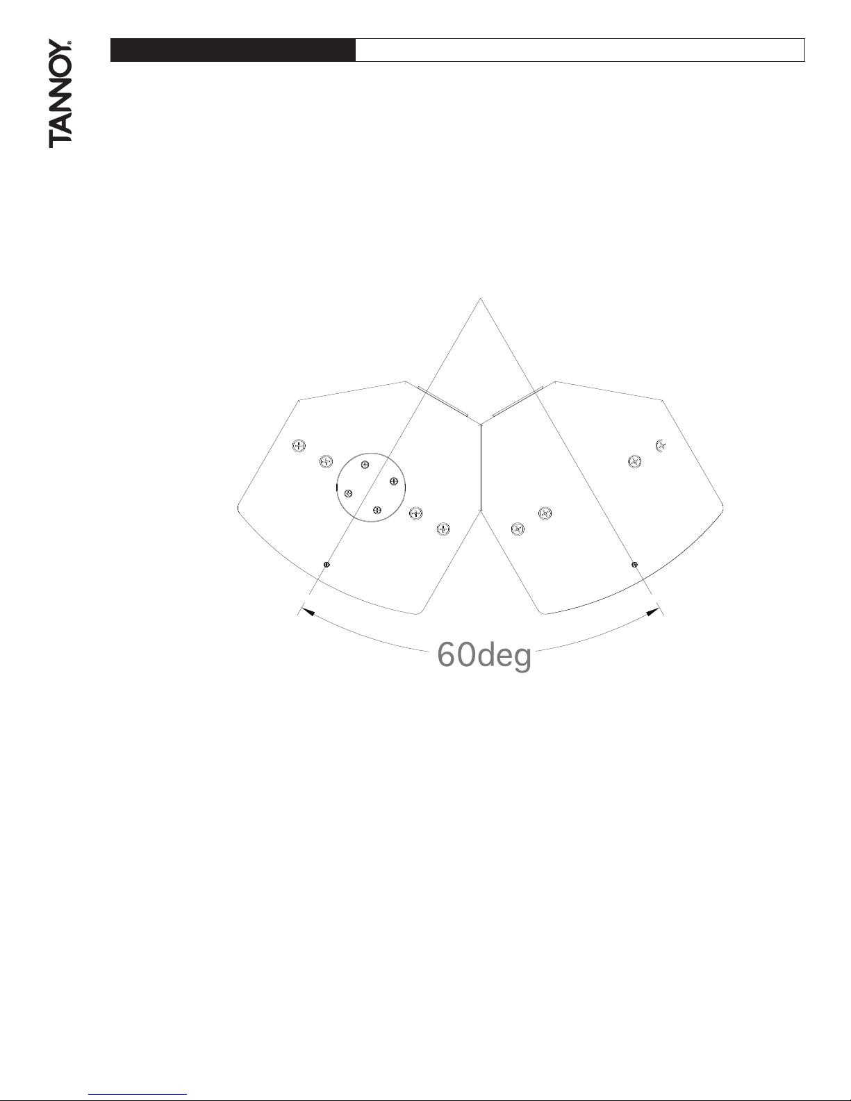
7.0: ARRAYING
As discussed in the previous section, comb filtering cannot be cured by equalisation. Small alterations to loudspeaker positions
can have the effect of minimising problematic combing frequencies. Arrays should be constructed so that the individual coverage
patters of each loudspeaker combine with minimal overlap. The design of the PowerV™ cabinet greatly simplifies the creation
of effective arrays, allowing seamless wide horizontal coverage using two loudspeakers without the need for tedious
experimentation.
By placing the PowerV™ cabinets with the 30 degree angled rear panels together, minimal dispersion pattern overlap is
achieved, guaranteeing an extraordinarily smooth transition. In many applications the 90-degree (75 - degree on the
PowerV12HP™ and PowerV15™) dispersion pattern may be sufficient in the horizontal plane.
It is also possible to stack the cabinets vertically using the above method, say for use in a central cluster, where greater vertical
dispersion is required.
As shown in the above diagram, one of the PowerV™ cabinets is inverted to allow the optimum splay angle to be achieved.
The grill can be simply removed from this cabinet and be replaced in the correct orientation. The grill is held in position by
the two fixing screws on the top and bottom lips of the cabinet.
9
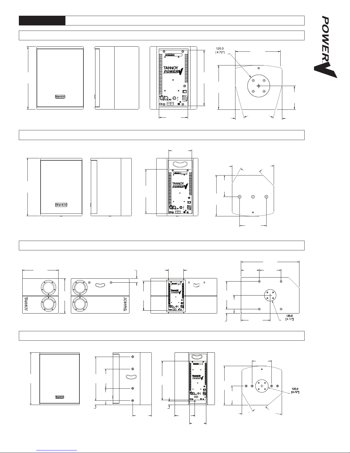
8.0 DIMENSIONS
LEVEL
INPUT
MODE
C
I
N
T
E
R
K
T
E
CM
U
S
E
L
I
S
T
D
LINK
B
A
0
POWER
500VA Max
115-230V
- POWER
10
- SIGNA L
- LIMIT
50-60Hz
TANNOY PART 3461 0913
REPLACE ON LY WITH
T10AL 250V
FUSE
THIS CLASS D DIGI TAL DEVICE MEETS ALL REQUIREMENTS OF THE
CANADIAN INTERFERENCE-CAUSING EQUIPMEN T REGULATIONS AND
OPERATION SUBJEC T TO CONDITIONS S TATED INTHE MANUAL.
THIS EQUIPMEN T MUST BE EAR THED
CAUTION
COMPLIES WITH PART 15 OF THE FCC RULES.
WARNING
TO REDUCE THE RISK OF FIRE OR ELECTRIC
SHOCK DO NO T EXPOSETHIS EQUIPMEN T TO
RISQUE DE CHOC ELECTRIQUE-NE PAS
RAIN OR MOISTURE
OUVRIR.
AVIS:
HIGH PASS
FILTER
FULL
RANGE
MODE A MODE B
125.0
[4.92"]
240.8
[9.48"]
15º
15º
334.0
[13.15"]
154.0
[6.06"]
296.0
[11.65"]
235.0
[9.25"]
A
B
LINK
LEVEL
50-60Hz
115-230V
500VA Max
MODE B
HIGH P ASS
FILTER
FULL
RANGE
MODE A
US
C
D
T
S
I
L
E
CM
E
T
K
R
E
T
N
I
FUSE
T10AL 250V
REPLACE ON LY WITH
TANNOY PA RT 3461 0913
POWER
INPUT
10
MODE
0
- SIGNA L
- POWER
- LIMIT
OUVRIR.
RAIN OR MOISTURE
RISQUE DE CHOC ELECTRIQUE-NE PAS
SHOCK DO NO T EXPOSE THIS EQUIPMEN T T O
TO REDUCE THE RISK OF FIRE OR ELECTRIC
OPERATION SUBJEC T TO CONDITIONS STATED IN THE MANUAL.
CANADIAN INTERFERENCE-CAUSING EQUIPMEN T REGUL ATIONS AND
THIS CLASS D DIGI TAL DEVICE MEETSAL L REQUIREMENTS OF THE
COMPLIES WITH PART 15 OFTHE FCC RULES.
CAUTION
THIS EQUIPMEN T MUS T BE EA RTHED
AVIS:
WARNING
45º
30º
275.0
[10.73"]
145.0
[5.66"]
180.0
[7.02"]
388.0
[15.13"]
296.0
[11.54"]
154.0
[6.01"]
AVIS:
OUVRIR.
RAIN OR MOISTURE
RISQUE DE CHOC ELECTRIQUE-NE PAS
SHOCK DO NOT EXPOSE THIS EQUIPMENT TO
TO REDUCETHE RISK OF FIRE OR ELECTRIC
WARNING
COMPLIES WITHPA RT 15 OF THE FCC RULES.
CAUTION
THIS EQUIPMENT MUS T BE EA RTHED
OPERATION SUBJECT T O CONDITIONS S TATED INTHE MANUAL.
CANADIAN INTERFERENCE-CAUSING EQUIPMEN T REGULATIONS AND
THIS CLASS D DIGITAL DEVICE MEETS ALL REQUIREMENTS OF THE
FUSE
T10AL 250V
REPLACE ONL Y WITH
TANNOYPART 3461 0913
50-60Hz
- LIMIT
- SIGNAL
10
- POWER
115-230V
500VA Max
POWER
0
A
B
LINK
D
T
S
I
L
E
U
S
CM
E
T
K
R
E
T
N
I
C
MODE
INPUT
LEVEL
LPF 2
110Hz
LPF 1
80Hz
MODE A MODE B
590.0
[23.23"]
185.0
[7.28"]
220.0
[8.66"]
295.0
[11.61"]
42.5
[1.67"]
280.0
[11.02"]
182.5
[7.19"]
365.0
[14.37"]
355.0
[13.98"]
296.0
[11.65"]
154.0
[6.06"]
42.5
[1.67"]
10
INPUT
D
E
C
T
S
I
L
E
T
R
E
T
N
I
US
CM
K
MODE
LINK
A
0
B
LEVEL
- POWER
- SIGNAL
- LIMIT
115-230V
500VA Max
50-60Hz
POWER
TANNOYPA RT 3461 0913
REPLACE ON LY WITH
T10AL 250V
FUSE
RAIN OR MOISTURE
OUVRIR.
THIS CLASS D DIGIT AL DEVICE MEETS ALL REQUIREMENTS OF THE
CANADIAN INTERFERENCE-CAUSING EQUIPMEN T REGUL ATIONS AND
OPERATION SUBJEC T T O CONDITIONS S TATED INTHE MANUAL.
THIS EQUIPMENT MUS T BE EARTHED
TO REDUCETHE RISK OF FIRE OR ELECTRIC
SHOCK DO NOT EXPOSE THIS EQUIPMENT TO
RISQUE DE CHOC ELECTRIQUE-NE PAS
CAUTION
COMPLIES WITH PART 15 OF THE FCC RULES.
AVIS:
WARNING
MODE BMODE A
FULL
RANGE
HIGHPASS
FILTER
486.0
[19.13"]
406.0
[15.98"]
180.0
[7.09"]
153.0
[6.02"]
40.0
[1.57"]
175.0
[6.89"]
359.0
[14.13"]
154.0
[6.06"]
180.0
[7.09"]
175.0
[6.89"]
360.0
[14.17"]
30º
50º
186.1
[7.33"]
34.0
[1.34"]
POWER V6
POWER V8
POWER VS10BP
POWER V12
 Loading...