

Page 1
OWNER’S MANUAL
Page 2

WARRANTY
This equipment has been produced and tested with care and precision. All Tannoy speaker systems are built to give first class service and carry a 5-year
warranty. Active subwoofers carry a 1-year warranty.
If the equipment proves to be defective within this period for any reason other than accident, misuse, unauthorised modification or fair wear and tear, Tannoy
will repair any such defect or, at our option, replace it without charge for parts, labour or return carriage. This warranty is given in addition to the customer's
statutory rights.
If you suspect a problem with your loudspeakers please contact your local Tannoy dealer who will be able to advise on appropriate action.
2
Thank you for selecting Tannoy loudspeakers; developed in the UK by our dedicated team of design engineers,
they are the choice of discriminating music and movie lovers the world over. Excellence is designed into our
loudspeakers from the start. Careful selection of the very best components combined with strict quality control
procedures during the production process ensures this level of excellence is maintained. We feel confident that
you will enjoy your new Tannoy loudspeakers for many years to come.
Please take time to read the rest of this owner’s guide before using your loudspeakers to gain maximum effect
from their use. Once you have installed your new loudspeakers please complete and return the registration
document – this does not limit your legal rights.
Loudspeakers are electromechanical devices that ‘run-in’ through use; performance will therefore improve after
an initial period of 24hrs continuous use. Once they have been further run-in over a considerably longer period,
there will be clear enhancement of the stereo imaging, mid-band quality and bass performance characteristics.
CONTENTS
INTRODUCTION 2
SUPERTWEETER™ TECHNOLOGY
3
CABLE CHOICE 4
STAND MOUNTING MODELS 5
CONNECTION IN SINGLE WIRE MODE 6
BI-AMPING 7
GRILLES 8
CENTRE CHANNEL SPEAKER 9
TECHNICAL SPECIFICATIONS 10
SET-UP DIAGRAMS 11-15
OWNER’S MANUAL
INTRODUCTION
Tannoy in-wall speaker systems offer a fresh perspective for the custom installation product arena. For the first time, highly regarded
cabinet-based monitor quality speaker systems are available as in-wall designs. These models have been designed therefore to provide
a performance level more in keeping with that of conventional loudspeakers. As a result Tannoy In-wall products find applications in MultiRoom audio installations, Home Theatre systems and in the many other applications where space is at a premium but ultimate sound
quality is still paramount.
Drive units and crossover assemblies, as used in many of the existing Tannoy loudspeaker ranges, have been utilised to ensure that sound
quality is not compromised, and a robust cable termination block is fitted to provide the speaker with optimum input signal integrity.
Complementing any style of décor, the perforated metal grille and discreet moulded ABS baffle panel frame can be painted to blend in
seamlessly with the domestic environment. The result is a system offering audiophile quality sound with minimal invasion of the living space.
Page 3
AMPLIFIER MATCHING
Consult the enclosed product specification sheet for the acceptable power range of amplifier matching. The high peak power handling
of Tannoy loudspeakers permits responsible use with more powerful amplifiers - please read the Warranty.
As with all loudspeaker systems, the power handling is a function of voice coil thermal capacity. Care should be taken to avoid overdriving
any amplifier, as this will cause output overload resulting in 'clipping' or distortion within the output signal. If amplifier output overload
conditions exist for an extended period then the loudspeakers can be damaged.
Generally a higher power amplifier running hard, but free of distortion, is less likely to damage the loudspeaker than a lower power
amplifier continually clipping. Remember also that a high powered amplifier running at less than 90% of output power generally sounds
a great deal better than a lower powered option struggling to achieve 100%. An amplifier with insufficient drive capability will not allow
the full performance of the loudspeakers to be realised (refer to the specification table in this manual for recommendations).
3
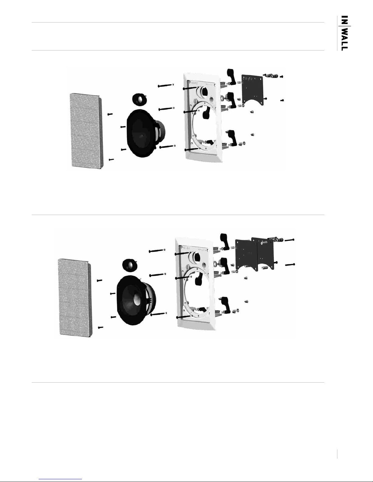
TANNOY IN WALL LOUDSPEAKERS | EXPLODED VIEW
iw6 DS DISCRETE MODEL
iw6 TDC DUAL CONCENTRIC™ MODEL
Page 4
CABLE CHOICE
Always use the best quality of cable available within your budget. High quality audio signals passing from the amplifier to the loudspeaker
are unusual in their demands on the cable. Wide dynamic range and frequency bandwidth information has to coexist with the ability to
transmit peak currents of at least 10amps, without incurring any loss or signal impairment. This explains why the sound quality of the
information reproduced by the loudspeakers is so dependant on the physical properties of the cables connecting them to the amplifier.
Technically, we recommend two-core cable with cross section area not less than 1.5mm2 (14 gauge) for cable runs of up to 3 metres.
For longer lengths we would suggest that you use cable with a minimum cross sectional area of 2.5mm2 (12 gauge). We do not recommend
the use of braided (Litz) or small diameter coaxial cables as these have a high capacitance that may affect the stability of certain amplifiers.
WIDEBAND™ TECHNOLOGY
Tannoy has incorporated its own WideBand™ technology into the design of both in-wall loudspeakers. Not only does this exceptional
in-house technology resolve the fine detail of high frequency information but it also effectively enhances the listening experience throughout
the whole frequency range. The WideBand™ high frequency system creates an increased immediacy, airiness and impact, making music
sound more natural and true to life.
Music contains transient information and rich harmonics beyond the range of human hearing for pure tones. Even bass notes have leading
edge transients reaching 30kHz. Operating between the roll-off point of the exclusive Tannoy mid-bass or Dual Concentric™ drive units
and 51kHz, the Tannoy WideBand™ high frequency unit will accurately reproduce the leading edge of individual notes allowing the listener
to experience the entire bandwidth information of instruments.
In addition, the extension of the frequency response, by fully two octaves, corrects time and phase response within the bandwidth of normal
human hearing. Taking these acoustical phase anomalies beyond the audible range adds realism to the soundstage through improvements
in imaging and the placement of instruments.
4
DRIVER TECHNOLOGY
The Tannoy In-wall range utilises two different driver assemblies, a discrete two-way driver array and the exclusive point source, constant
directivity driver, the Tannoy Dual Concentric™ with additional SuperTweeter™.
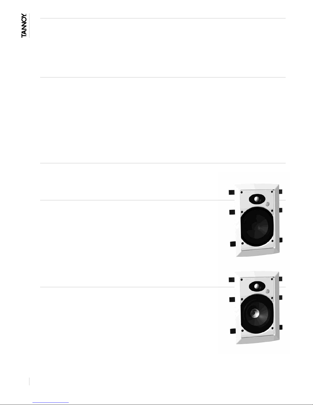
iw6 DS DISCRETE MODEL
The main bass and mid-range driver, built around an immensely strong chassis, is used in the
entry-level model in the range. Its rigid construction controls the energy created by its long throw
driver with consummate ease, a crucial factor in creating a drive unit capable not only of high power
delivery and tremendous bass output, but also of great subtlety and finesse.
The clean and open midrange performance of the iw6 DS is further enhanced through smooth
transition to the extended bandwidth performance of the exclusive Tannoy WideBand™
high frequency unit.
iw6 TDC DUAL CONCENTRIC™ MODEL
The latest Tannoy Dual Concentric™ driver has been incorporated into the iw6 TDC. Intensive research
and development has produced an all-new version of this proven technology that builds upon the
legendary performance of this exclusive Tannoy driver design.
The time coherent, point source and constant directivity nature of the dispersion characteristics inherent
in the Dual makes it an accepted industry standard in studio monitoring. By exceeding the rigorous
demands of the recording and mastering environment Tannoy can ensure that playback performance
in the home, whether installed in two channel stereo, multi channel home cinema or in distributed
audio multi-room applications, is strictly controlled to accurately reflect the sound engineers artistry.
In nature all sounds emanate from a single point in space. The high frequency unit of the Dual,
centrally mounted in the throat of the main mid/bass driver, is so positioned as to acoustically replicate
this single point source; delivering an open and natural sound with a very wide imaging ‘sweet spot’, which creates an expansive soundstage
with remarkably focussed placement of vocals and instrumentation.
This class leading performance is further enhanced by the inclusion of a Tannoy SuperTweeter™ to extend the frequency bandwidth to
over 50kHz. Greater precision, tighter imaging and increased presence are assured throughout the entire audible frequency band; even
with normal Red Book Standard 20kHz limited CD software.
Page 5

5
TERMINAL PANEL CONNECTIONS AND DRIVER EARTHING
iw6 DS DISCRETE MODEL
In this model there are two robust spring loaded terminals designed to take substantial high
quality loudspeaker cable. Strip off approximately 8mm (1/4”) of the outer protective layer
and twist the inner cores together. Depress the spring-loaded terminal and insert the core
ensuring that correct polarity is maintained.
iw6 TDC DUAL CONCENTRIC™ MODEL
The iw6 TDC Dual Concentric™ model has an extra spring loaded terminal designed to
optimise performance further by taking advantage of the driver earthing facility.
Use a shielded or screened loudspeaker cable; connecting the screening termination to the
earth or ‘ground’ (green) terminal on the loudspeaker and to the ground or earth connection
on the amplifier. Alternatively if you are not using a screened loudspeaker cable but wish to
utilise the earthing facility, run a single cable between the earth or ‘ground’ (green) terminal
on the loudspeaker to the earth (ground) connection on the amplifier. Connect the positive
and negative cables In the same manner as in the discrete model while ensuring correct
polarity.
The earth (green) terminal comes fitted with a blanking plug. Remove this to insert the cable
but retain the plug for future use. The product should not be installed without either this plug
or a cable in place as the energy from the driver can in extreme cases cause audible
resonance.
WALL CLAMP MECHANISM
PLEASE CONSULT THE INSTALLATION SECTION
OF THIS MANUAL BEFORE PROCEEDING.
A unique six way clamp mechanism (patent applied for: 0316892.9)
has been designed to provide the acoustically optimum bond to the
wall surface without risk of distortion to the loudspeaker baffle.
As the six screws are tightened the immensely strong polycarbonate
clamping arms will automatically swing round into the locking position,
locating securely to the inside of the wall surface.
The design also allows for simple removal or reorientation of the
loudspeaker. The spring-loaded clamp mechanism ensures that as the
screws loosened (turned anticlockwise) the clamp arm travels along its
guide before turning itself into the rest position. The captive locking
system ensures that the clamp arm cannot drop off the end of the
screw to be lost in the wall cavity.
IMPORTANT
Get all the clamps in the rest position by loosening all screws before attempting
to remove the speaker from the wall.
Page 6

INSTALLATION
WARNING
If adding new speakers to an existing installation, or simply replacing old ones, you must ensure that the amplifier driving the system is
switched OFF.
WARNING
Prior to proceeding with the installation ensure that you determine the position of electrical cabling, pipe work and wall studs. Having
selected a wall location clear of any obstruction measure carefully to ensure the correct placement.
PAINTING
Before proceeding with the installation the grille and baffle panel can be painted to blend with the surrounding décor.
When painting the baffle be sure to carefully mask off the driver assemblies. It is important to ensure that paint does not come into
contact with the cone, roll surround or HF unit. Several thin coats of paint will provide a superior finish to that achieved by one applied
too thickly.
The speaker is supplied with a sheet of acoustically transparent protective foam fixed to the inside of the grille. Having painted the grille
to match the room décor please remove the original foam and replace with the spare sheet supplied in the accessory pack. It is important
that this replacement foam is bonded to the grille over it’s entire area, using a suitable spray adhesive. Failure to do so will result in
audible resonace.
OVERVIEW
Tannoy In-wall loudspeakers have been designed for installation into standard stud partition wall systems constructed with 102mm by
51mm (4“ by 2”) timber at 406mm (16”) centres. However, it is envisaged that they will generally be used in cavity wall installations
constructed with standard thickness plasterboard. These are guidelines and therefore do not preclude use of the Tannoy In-wall products
in different locations and a wide range of other wall construction types as long as they have a secure clamping surface up to maximum
thickness of 25.4mm (1”).
Driver cone movement at low frequencies may become excessive unless steps are taken in the wall cavity void behind the loudspeaker to
provide a well sealed and accurately controlled rear ‘enclosure’ volume, this will effectively act as an ‘enclosure’ behind the speaker
(see Speaker Loading Volume section in this manual). Failure to ensure this will affect the bass and midrange performance unfavourably.
POSITIONING
There is a great deal of mounting location flexibility with both models when used in home cinema or multi channel systems. In particular,
please note that due to the unique point source symmetrical dispersion properties of the Tannoy Dual Concentric™ drive unit, the model
iw6TDC can be mounted in either portrait (in stud partition wall situations) or landscape positions where sufficient space exists behind
the wall surface.
To achieve the optimum spectral and stereo performance select your mounting location as follows:
Vertical plane
Align the front baffle centres at intended listening height, usually dictated by the normal seated listening position. For audio use, when
positioned in front of the listener, this will usually be in the range of 1100mm to 1700mm (43” to 67”). As home cinema rear effects
speakers mounted on the rear walls of the room, the mounting height range is 1530mm to 2140mm (60” to 84”).
Horizontal plane
The loudspeakers should be located between 1500mm to 4500mm (60” to 180”) apart – the room size and shape will dictate the final
mounting location, but generally the listening position, when used as a stereo pair, should be set slightly further away than the speakers
are apart.
Where the In-walls are used as rear effects speakers in a home cinema system the ideal viewing point will establish the distance from
the rear wall to the listening position. Avoid positioning the loudspeakers in corners of the room, as this will have a negative effect on
performance; maintain a distance of 1000mm (39”) from a corner.
SPEAKER FITTING
REMEMBER…. MEASURE TWICE – CUT ONCE!
Once the mounting location has been selected use the template provided to mark out the area of wall material to be cut out. Carefully
remove the waste, checking again that there are no interferences from studs/wire/pipes etc.
Install the loudspeaker cabling ensuring that the wiring route is laid clear of all screws and nails that could potentially damage the cable
insulation. Allow sufficient cable length at the speaker end to allow for unrestricted connection.
It is necessary to block off the void behind the speaker by suitable means (insulation material or foam) to create an “enclosure” area.
This will offer the speaker the required loading volume as detailed in the specification section of this manual.
It is important to provide some acoustic damping between the speaker and the rear wall surface. We recommend use of a BAF sheet
(Bonded Acrylic Fibre). Ensure that materials used comply with local fire and building regulations.
6
Page 7

7
Strip 8mm (1/4 inch) of shielding from the end of the speaker cables in preparation
for connection to the spring terminals on the rear of speaker. Check that the
clamping arms are aligned as shown prior to insertion in the wall.
Connect the speaker cable observing the correct wiring polarity. The positive
terminal (marked + and coloured red) should receive the positive cable (usually
marked with a repeated stamped name, line or raised rib) and the negative
terminal (marked – and coloured black) the negative cable.
Insert the baffle into pre-prepared hole in the wall, ensuring that the speaker wire
is located securely away from the driver – contact with the driver cone will cause
annoying buzzes.
Each of the six clamp screws can now be tightened (clockwise). Starting at one
corner then moving to the opposite corner, tightening sufficiently to check for
visual orientation, before proceeding to tighten the other two corners. Finish off
by tightening the two middle clamps.
WARNING
Do not over tighten the screws – this is unnecessary to achieve a strong acoustic
seal to the wall and risks damaging the wall surface
Repeat the installation procedure for the other loudspeakers and complete the
connection process to the amplifier. Once again ensure that correct cable polarity
is observed.
Switch on the amplifier with the volume control at its lowest setting. Select a signal
source and slowly turn up the volume to a low level. Check that bass and treble
information comes from both speakers – if not, switch off the amplifier and recheck
the connections.
Carefully check the area surrounding the installation and ensure that there are
no buzzes or rattles that could potentially impair enjoyment of the system – If
there are then locate and silence the causes using cable ties or suitable packing
material.
Optimum performance will be assisted by the use of silicone sealant, or similar
material, to seal gaps, for instance, between the studs and the wallboard material.
This cavity sealing will help to create a near airtight seal.
GRILLE FITTING AND REMOVAL
The grille should be carefully fitted to the front baffle aperture, by lining up the
edges of the grille carefully with the baffle. To avoid indentation damage do not
press the centre of the grille; apply even pressure to the corner as it is pressed
firmly into position.
To remove the grille loop an opened paper clip, or similar length of firm wire,
through two holes near a corner and pull gently. The grille is intended to be a
tight fit, so insert the wire at each corner in turn pulling carefully to avoid distortion
of the mesh.
Page 8

8
NOTE
SPEAKER LOADING VOLUME
There are two simple approaches to achieve a sealed ‘enclosure’ to provide the correct driver loading area behind the speaker. The chosen
method will depend on whether the wall is under construction, as in a new building project, or an existing wall where access is limited.
Option 1
Stud partition walls under construction, with 102mm by 51mm (4 by 2 inch) timber at 406mm (16 inch) centres.
Block off the cavity, above and below the intended speaker opening, with the same framing timber. The distance that these two internal
barriers should be separated by is shown below in Fig 1.
If the stud centres are greater than 16” apart then insert two timbers vertically between the blocking timbers to create the desired loading
volume. See Fig 2.
System iw6 DS iw6 TDC
Separation mm (inches) 410 (16) 550 (21.5)
Option 2
Existing timber stud partition, or any other wall type with constructed with a 406mm (4 inch) cavity depth.
Many professional installers use a ‘doughnut’ of compliant material, which can be inserted as a tight fit between the two surfaces
of the partition or into the wall cavity. The length of the internal surface of the strip of material determines the ‘enclosure’ volume.
Cutting the strip to the length shown below and joining to form a ring will ensure the correct volumes.
System iw6 DS iw6 TDC
Separation mm (inches) 1380 (54) 1570 (62)
FIG 1 STUD PARTITION UNDER CONSTRUCTION –
16” TIMBER CENTRES
INSIDE STUD PARTITION
VIEWED FROM REAR
NEW TIMBER TO
CREATE ENCLOSURE
EXISTING TIMBERS
BACK OF SPEAKER
FIG 2 STUD PARTITION UNDER CONSTRUCTION –
TIMBER CENTRES OVER 16”
INSIDE STUD PARTITION
VIEWED FROM REAR
NEW TIMBER TO
CREATE ENCLOSURE
EXISTING TIMBERS
BACK OF SPEAKER
FIG 3 STUD PARTITION OR WALL CAVITY USING
COMPLIANT MATERIAL OF APPROPRIATE
THICKNESS TO CREATE TIGHT SEAL
INSIDE WALL VIEWED
FROM REAR
‘DOUGHNUT’ OF
COMPLIANT MATERIAL
BACK OF SPEAKER
Page 9

9
DRIVE UNITS
SuperTweeter™ high frequency
Dual Concentric™ high frequency
Dual Concentric™ low frequency
WideBand™ high frequency
Low frequency
Shielded
25mm (1") 25-micron titanium dome, neodymium
magnet system
165mm (61/2”) Multifibre paper pulp cone
No
25mm (1") 25-micron titanium dome, neodymium
magnet system
25mm (1") 25-micron titanium dome, neodymium
magnet system
165mm (61/2") Multifibre paper pulp cone
Yes
CABINET
Materials
Dimensions - inc grille mm (inches)
Volume - litres (cubic feet)
Weight (each) - kgs (lbs)
Finish options
Baffle Panel: Moulded ABS
Clamps: Moulded Polycarbonate
320 x 209 x 98 (125/8 x 81/4 x 37/8)
N/A
2.8 (6.1)
White
Baffle Panel: Moulded ABS
Clamps: Moulded Polycarbonate
320 x 209 x 104 (125/8 x 81/4 x 41/8)
N/A
3 (6.6)
White
CROSSOVER
Crossover frequency
Crossover Type
HF Adjustments
2.7kHz
2nd order LF, 3rd order HF
±1.5dB
1.8kHz, 16kHz
1st order LF, 1st order high pass HF
±1.5dB
PERFORMANCE
Recommended amplifier power
Watts RMS
Continuous power handling
Watts RMS
Peak power handling - Watts (1)
Sensitivity (2.83 Volts @ 1m) (2)
Nominal Impedance - Ohms
Low frequency alignment (-6dB)
Frequency response -6dB (3)
iw6 DS | IN WALL DISCRETE
20-100
75
225
90dB
8
44Hz
44Hz-51kHz
iw6 TDC | IN WALL DUAL CONCENTRIC™
20-150
110
325
91dB
8
36Hz
36Hz - 51kHz
TECHNICAL SPECIFICATIONS
(1) Long-term power handling capacity as defined in EIA standard RS426A
(2) Averaged over specified bandwidth for half-space environment. For anechoic conditions the figure is to bedecreased by 3dB.
(3) +/- 6dB, measured at 1metre in anechoic chamber in a critically tuned enclosure.
Page 10

10
TECHNICAL DRAWINGS
iw6 DS DISCRETE MODEL
TOP
REAR SIDE FRONT
BOTTOM
93.0
271.5
NEGATIVE (-)
(BLACK TERMINAL)
POSITIVE (+)
(RED TERMINAL)
168.5
209.0
320.0
Page 11

11
iw6 TDC DUAL CONCENTRIC™ MODEL
TOP
FRONT
BOTTOM
REAR
168.5
271.5
POSITIVE (+)
(RED TERMINAL)
NEGATIVE (-)
(BLACK TERMINAL)
'EARTH' OR 'GROUND'
(GREEN TERMINAL)
SIDE
209.0
320.0
99.0
Page 12

Tannoy United Kingdom T: +44 (0) 1236 420199 F: +44 (0) 1236 428230 E: enquiries@tannoy.com
Tannoy North America T: (519) 745 1158 F: (519) 745 2364 E: inquiries@tannoyna.com
6483 0404
 Loading...