

Page 1

Dual Concentrics for Contractors
INTRODUCTION
For over 40 years Tannoy has been manufacturing Dual Concentric drive units and loudspeaker systems. Over that time the loudspeaker industry has developed increasingly sophisticated drive units and horn systems to control the way sound is dispersed into the world. They
have tried, in part, to duplicate the inherent advantages of the true point sour ce – the
Tannoy Dual Concentric.
Tannoy has continued to develop the Dual Concentric concept, even when other more overtly
‘modern’ products such as the constant directivity hor n wer e capturing the headlines.
It is popular to say that loudspeakers haven’t changed at all in the last half century. But
there have been a huge number of incremental improvements pr oduced by better understanding of the nature of sound propagation, the use of vastly improved development tools
and computers, and the use of ever more sophisticated materials and manufacturing techniques. As well as sounding so much better, today’s drive units have the power, reliability
and SPL capabilities of a dozen of their earlier predecessors.
Whilst standing the test of time, the Tannoy Dual Concentric has not stood still. Tannoy has
been constantly improving the capabilities of the drive units, and recently our engineers
returned to first principles and designed an entirely new drive unit. This new unit applies
Tannoy’s long experience and advanced understanding of loudspeaker and acoustic theory
taking the Dual Concentric into the next century.
In this White Paper some of the inherent advantages of using a point source, and why the
Dual Concentric is seeing a renaissance in the contractor industry, are explained.
© Tannoy Ltd May 1992/June 1996 Part No. 6483 0283
®
Page 1
Page 2
ONE SOURCE IS BETTER THAN TWO
In the ideal world manufacturers would like to produce a single drive unit that copes with all of the
frequency range. But the laws of physics being what they are, a driver that works well for low frequencies will not work well for high frequencies and visa versa. So separate drive units are used for different areas of the frequency band. Most manufacturers have developed completely different drive units
and placed them in a single box or in several boxes to create a full range system.
Unfor tunately as soon as you br eak the audio signal into separate sections and transmit it from different points in space all sorts of problems occur.
LARGE PISTON AREA
LARGE POWER INPUT
MORE OMNIDIRECTIONAL
CABINET NEEDED
Sound pressure (dB)
10 100 10000 200001000
DISPLACEMENT OF SOURCES
TIME ALIGNMENT
PHASE DIFFERENCES
Frequency (Hz)
SMALLER PISTON AREA
LESS POWER INPUT
CONTROLLED DISPERSION
DIFFRACTION CONSIDERATIONS
• Covering the whole audio spectrum requires differ ent approaches at differ ent
frequencies for optimum solutions.
• A seamless joining together at crossover is essential.
© Tannoy Ltd May 1992/June 1996 Part No. 6483 0283
®
Page 2
Page 3
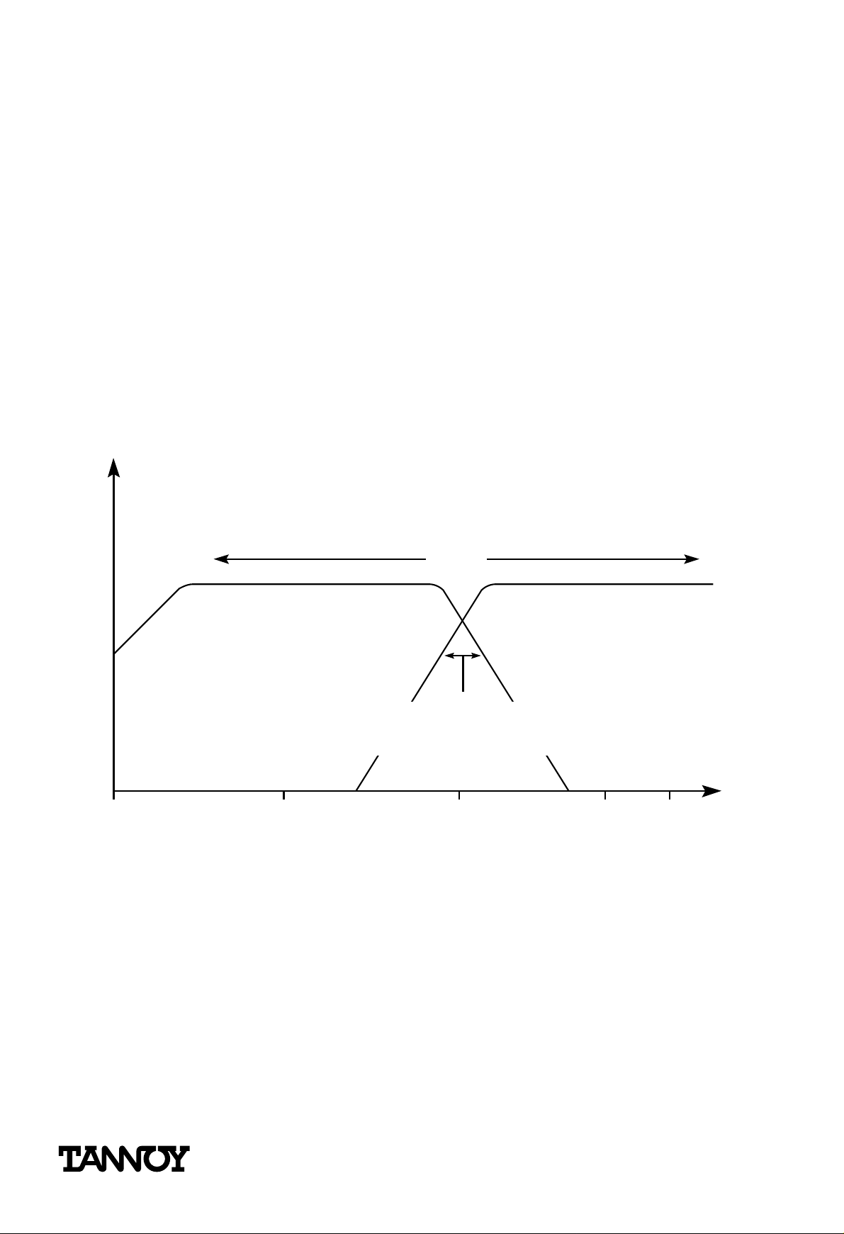
Inter ference over the critical cr ossover ar ea
Over the crossover area, both HF and LF drive units are producing acoustic energy. Since the drive
units are a little (or sometime large) distance away fr om each other, the signal path to the listener
from the HF and LF drive units will be slightly dif fer ent. The sound from the mor e distant driver will
take slightly more time to reach the listener than from the nearer one.
In one seat, the sound from the two drive units will be in phase with excellent perceived level, but in
a nearby seat they could be out of phase and the level will be down or even reduced to zero over a
narrow band of fr equencies. Consequently when separated HF and LF drive units are used, the sound
coverage in the crossover area will always be somewhat inconsistent.
One way to get over this is to use very steep crossover slopes, so the crossover area, where both
drive units are working, is minimised. However, steep filters can create phase errors and other electronic artefacts generating more problems than they solve.
Phase Error Changes with Position
HF
SOURCE
Bass Cab
Plan View
LF
SOURCE
OUT OF PHASE AT CROSSOVER
IN PHASE AT CROSSOVER
OUT OF PHASE AT CROSSOVER
HF horn
Ver y Steep Filter Slopes Less Steep Filter Slopes
Very Steep Filter Slopes
Less Steep Filter Slopes
AMPLITUDEPHASE
0
AMPLITUDEPHASE
0
• A true Point Source gives the same sound from seat to seat.
• Dual Concentrics can use simpler, better sounding and more ef ficient crossovers.
© Tannoy Ltd May 1992/June 1996 Part No. 6483 0283
®
Page 3
Page 4
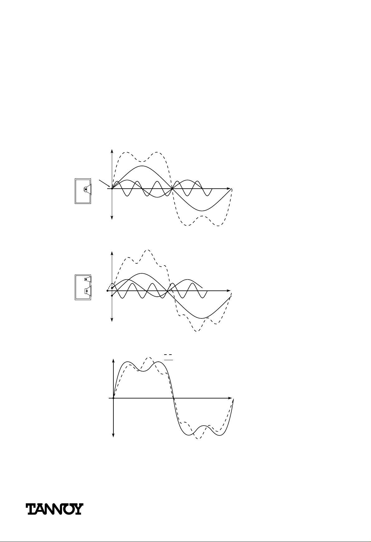
Harmonics
Every sound created in the natural world has harmonics that give us clues to the type and quality of
the signal source. The harmonics of a single note may extend beyond the limits of hearing.
A fundamental note, with fundamental frequency lying within the range of the LF driver, will have
many harmonics repr oduced through the HF driver. If these are separated, either in time or space,
then in most listening positions the fundamental of the note will be heard at a slightly dif fer ent time
to its harmonics, which does not lead to the most accurate reproduction of the sound.
The Tannoy Dual Concentric Preser ves the Harmonic Str uctur e of Complex Sounds
RESULTANT
POINT
SOURCE
FUNDAMENTAL
THIRD HARMONIC
SECOND HARMONIC
Time
Harmonic relationships preserved using a single point source
DIFFERENT RESULTANT
DISPLACED
SOURCES
Time
Harmonic relationships using multiple sources
DISTORTED MULTIPLE-SOURCE RESULTANT
ORIGINAL SINGLE-SOURCE RESULTANT
Time
Signal
Original versus distorted resultant
• Dual Concentrics have better harmonic alignment.
• Better harmonic alignment results in a clearer, more intelligible, more natural sound.
© Tannoy Ltd May 1992/June 1996 Part No. 6483 0283
®
Page 4
Page 5
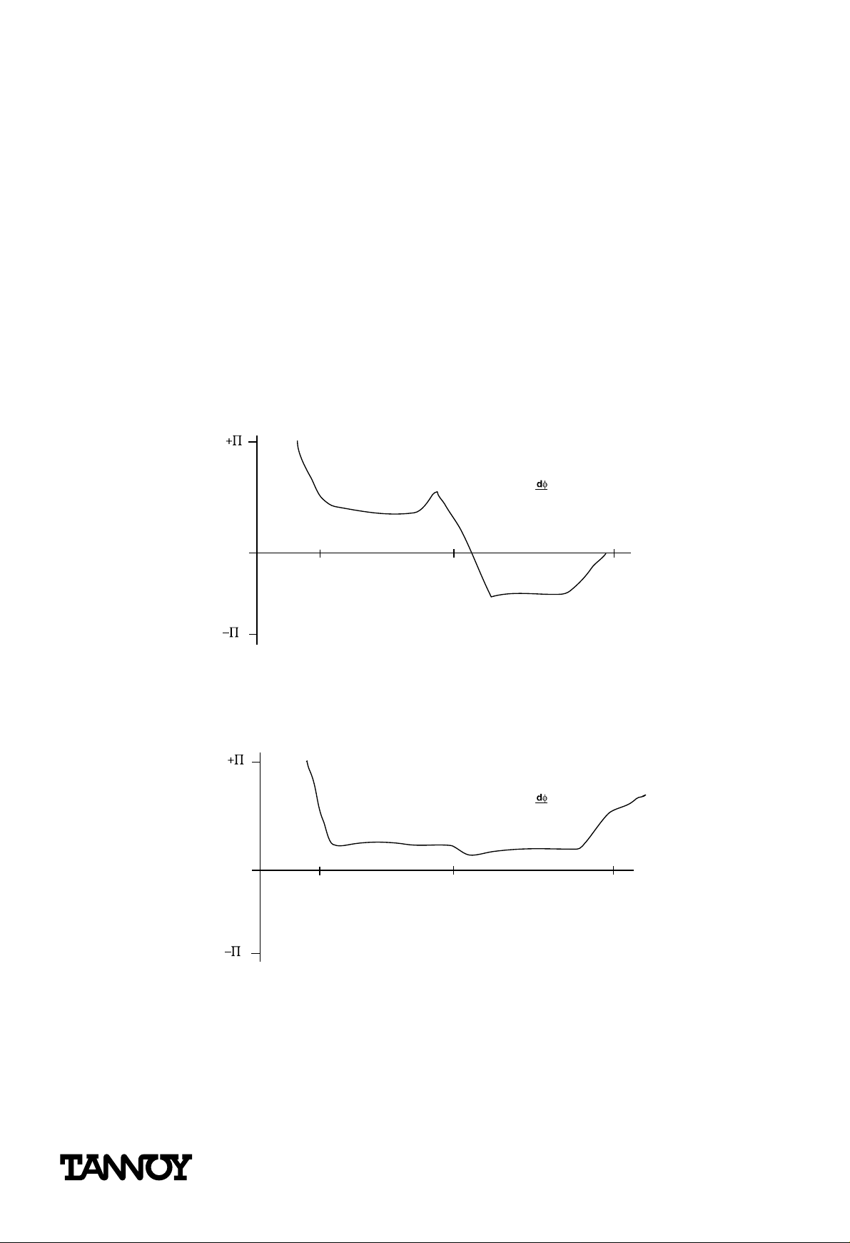
Constant Time Delay
A single pulse of sound, such as a drum beat can be considered a combination of many acoustic elements up and down the frequency spectrum. A loudspeaker system should behave as a constant
time delay with every element of the audio spectrum being delayed by the same amount as it passes
through the driver and crossover.
If, as is often the case with complex crossovers and separate drive units, the delays are different for
dif ferent ar eas of the audio spectr um then these elements will be hear d slightly staggered. The
‘crack’ of the stick hitting the drum skin from the ‘thump’ of the lower fr equencies produced by the
drum skin vibrating will be heard as separate events.
This can only be par tially r esolved by introducing delay pr ocessing to re-align the elements. Additional
processing, with its associated signal degradation, is made unnecessary by using a Dual Concentric.
Phase Response of a Typical Discrete Non-Aligned System
(180°)
= K
/
df
0
F
DS
(-180°)
Phase not independent of frequency
Phase Response of a Typical Tannoy Dual Concentric System
(180°)
0
100 Hz
Phase substantially independent of frequency
(-180°)
F
DC
20 kHz100 Hz
.
= K
.
df
20 kHz
• An integrated Dual Concentric approach provides a constant time delay.
• Constant time delays over the frequency spectrum give better overall sound quality and transient perfor mance.
• Constant time delay behaviour removes the need for separate HF delay lines that need careful and time consuming on-site adjustments.
© Tannoy Ltd May 1992/June 1996 Part No. 6483 0283
®
Page 5
Page 6
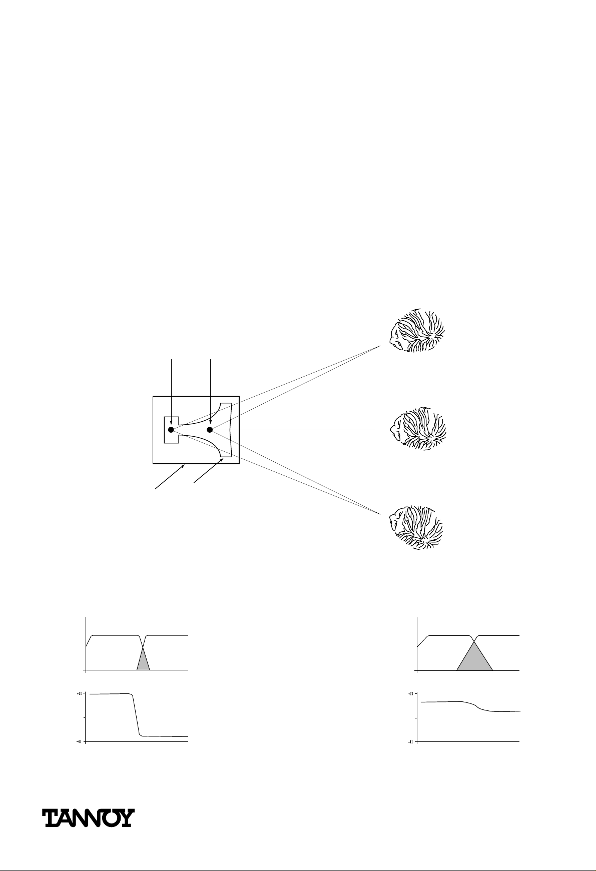
Attempts to emulate the Dual Concentric
There have been two trends in system design to try and emulate the single source approach. The
first is to bolt the HF horn in front of the LF or MF sections. This places the two sources in the same
axis but only in two planes – one driver is still in front of the other. To integrate the signals, some
form of delay has to be applied to one unit to make it coherent with the signals coming fr om the
other unit. This is costly to do well, making the crossover very complex – and complex crossovers
can af fect sound quality or use up power that could be better used powering the driver.
As well as creating problems within the electronics, placing the HF driver and hor n directly in fr ont of
a low frequency driver produces a whole set of non-linearities caused by the LF waves being masked
and reflected back onto the driver cone.
Engineers are increasingly concerned with the acoustic effects of relatively acoustically transparent
obstacles such as the grilles. Placing a large solid HF driver or a less solid (and more r esonant) horn
with all the associated mounting hardware directly in the way of the LF driver is not a satisfactory
engineering solution.
A Tannoy Dual Concentric does not suf fer from r eflected energy storage or mid-range
shadowing
LF LF
Obstruction and
interference
Single
horn profile
HF
HF
Discontinuity
of HF
Typical Coaxial unit Tannoy Dual Concentric
• A Point Source driver simplifies nearly every aspect of a system installation.
• The Dual Concentric is the only practical way of creating a full frequency range Point Source
driver.
• Other ways of approaching the Point Source goal suf fer from identifiable drawbacks.
© Tannoy Ltd May 1992/June 1996 Part No. 6483 0283
®
Page 6
Page 7
More attempts to emulate the Dual Concentric
Another trend in system design is to create systems from full-range cabinets, rather than separate
bass, mid and HF cabinets, which were the fashion in the 70s and early 80s. For both hire and
installation work the convenience of the compact full range cabinet, inherent in the Dual Concentric
approach, is becoming increasingly appreciated. But bringing the drive units closer together in smaller boxes of fers only partial solutions to the problems of time domain, phase, dir ectivity, crossover
complexities.
A well designed Dual Concentric drive unit resolves these problems by being a tr ue point source.
HF SOURCE
MF SOURCE
LF SOURCE
HF, MF AND
LF SOURCE
• Compact, full range boxes are the system design route for the 90s.
• Even in a small box, separated drive units cannot emulate a true point source unit, they will
still suffer from all the pr oblems of being of non Dual Concentric design.
© Tannoy Ltd May 1992/June 1996 Part No. 6483 0283
®
Page 7
Page 8
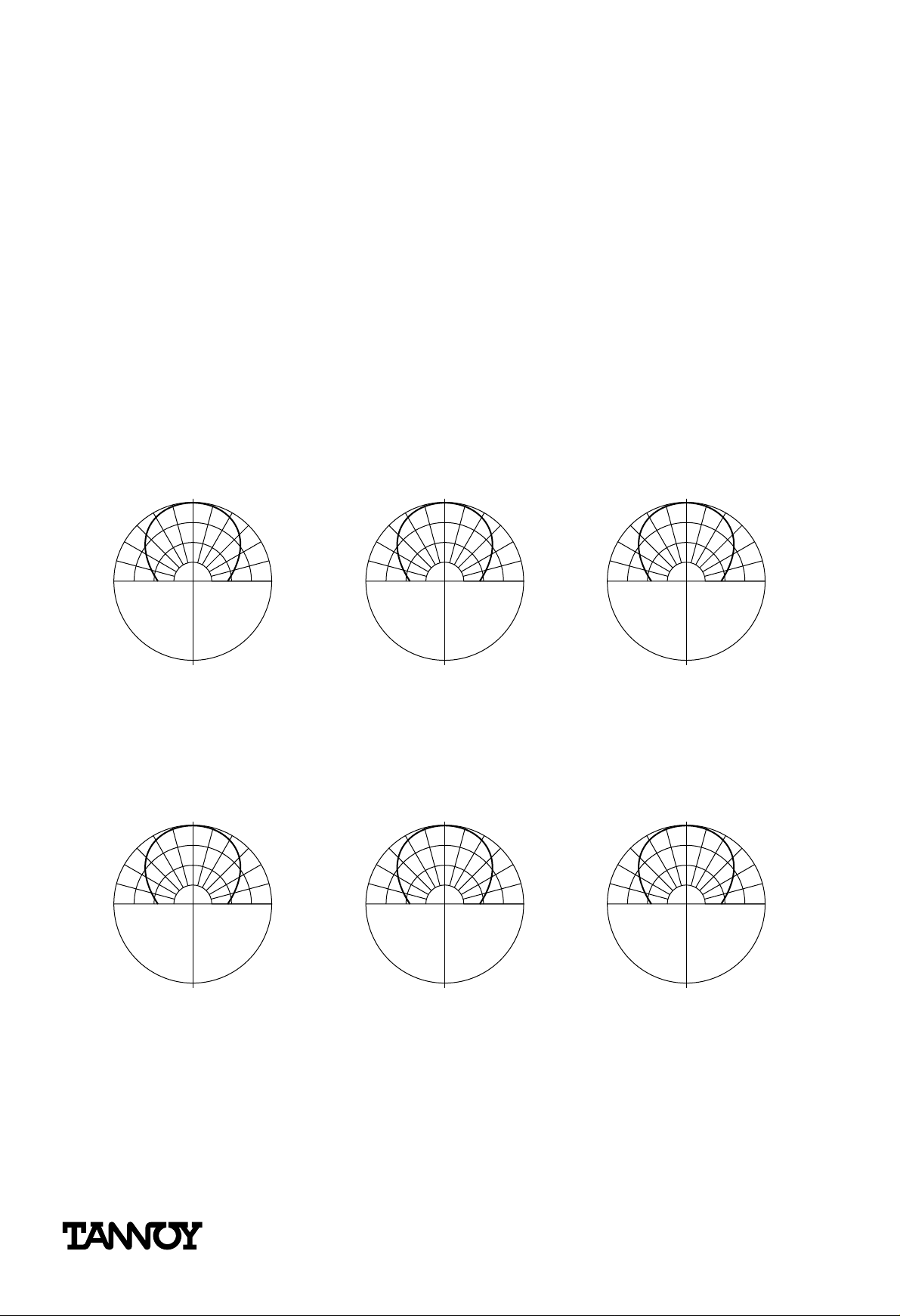
ONE DRIVER – ONE DIRECTIVITY
A lot of energy has gone into the design of constant directivity hor ns that control the acoustic dispersion from the HF driver. This is important to maintain an even coverage at all fr equencies over the
target area.
Controlling the directivity also allows the sound from the speaker to be more accurately targeted to
where it is needed. Targeting keeps the sound wher e you want it, and away from the walls and ceiling. This cuts down the amount of high level reflections that cause at best, reduced intelligibility, and
at worse, resonances and feedback.
In this age of tighter controls on working conditions it is also important to keep sound levels down in
work areas. Levels that are acceptable on a discotheque floor, will not be acceptable in the nearby
bar area where staff are working all the time.
Dispersion pattern for Constant Directivity
0°
30°
60°
270°
90°
1kHz
270°
5kHz
Dispersion pattern for Non-Constant Directivity
0°
30°
60°
270°
90°
270°
0°
30°
60°
90°
270°
0°
30°
60°
90°
10kHz
0°
30°
60°
90°
270°
0°
30°
60°
90°
1kHz
5kHz
10kHz
• The ideal system is one where the sound dispersion is well controlled, and does not dramatically alter with frequency.
• Dispersion control must be achieved without introducing problems in other areas
© Tannoy Ltd May 1992/June 1996 Part No. 6483 0283
®
Page 8
Page 9

Two drive units – two directivities.
At very low frequencies all systems radiate omni-directionally. From a few hundred Her tz and above,
dispersion control can be introduced by mechanically and acoustically adjusting the radiated wavefront.
The problem with most two or three-way speaker solutions is that while the HF is cor rectly contr olled
with a constant directivity horn, the mid and mid/low frequency speakers ar e left to fend for themselves. Consequently the radiation pattern for the high frequencies is completely different to the radiation pattern produced by the lower frequency drive units.
With dif ferent dispersions at different frequencies, the off-axis frequency versus amplitude r esponse
will be quite dif ferent to the on-axis r esponse. The difference in sound balance will also not be consistent. It will depend on where you are sitting, and what frequencies are being handled at the time.
Also with widely dif fering dispersion patter ns the amount of ener gy being radiated into the room
varies enormously with frequency. Peaks and troughs of energy aggravate the unpredictability of a
room’s performance, making it impossible to introduce equalisation that meets the r equirements
both of on-axis response and even room ener gy perfor mance.
By designing the Dual Concentric as an integrated full range driver, Tannoy can produce a consistent
conical directivity pattern uniquely across a much lar ger portion of the fr equency range. Except for
the very low omni-directional frequencies, what you get on axis is an even response; what you get
of f-axis is the same even response. The energy going into the room is controlled, for natural and
highly intelligible sound reproduction.
Typical Discrete system with horn HF Typical Tannoy Dual Concentric
PROPAGATES
FULL BANDWIDTH
PHASE COHERENT
WAVEFRONT
HF SOURCE
ACOUSTIC
POINT
LF SOURCE
SOURCE
• With a Dual Concentric the dispersion is smooth and consistent down to the point at which
the speaker starts behaving omni-dir ectionally.
• Varying dispersion aggravates room response problems making it more dif ficult to set up the
system.
• Uneven dispersion gives unpredictable sound balances.
• Controlled, even dispersion gives greater intelligibility in dif ficult r everberant rooms.
© Tannoy Ltd May 1992/June 1996 Part No. 6483 0283
®
Page 9
Page 10

Spherical Wavefront Generation
The Tannoy Dual Concentric high frequency waveguide ensures that spherical wavefronts and a good
acoustic directivity match with the low frequency driver. In this way there are no discontinuities in the
dispersion characteristics of the cone driver and the HF horn, in the critical crossover area. This is
simply not possible to achieve with separated drive units.
Spherical radiation provides a perfectly even and predictable dispersion symmetrically in both horizontal and ver tical planes. It contr ols the sound precisely to wher e you want it, and ensures that the
coverage is the same over the majority of the frequency range.
Truly Spherical Wavefront Generation
Waveguide
Spherical
wavefront
Diaphragm
• The Dual Concentric has a spherical dispersion for consistent perfor mance vertically and horizontally.
• The Dual Concentric’s spherical dispersion is symmetrical.
• On-axis and off-axis performance remains consistent across the frequency spectr um.
• The audience hears the same high quality perfor mance wherever they ar e.
© Tannoy Ltd May 1992/June 1996 Part No. 6483 0283
®
Page 10
Page 11

Better control where you want sound
With essentially one directivity pattern across the low/mid, mid and high fr equency spectr um, the
amount of energy being placed anywhere within the speaker’s coverage ar ea will be consistent. With
a true conical dispersion, coverage will not seriously vary with frequency.
Typical Tannoy Dual Concentric
ACOUSTIC
POINT
SOURCE
• Even dispersion means even coverage.
• Sound quality is consistent across the floor area.
• Designing the HF and cone drive units as a single system resolves dispersion disparities at
the crossover area.
© Tannoy Ltd May 1992/June 1996 Part No. 6483 0283
®
Page 11
Page 12

The problems of sound where you don’t want it
It is impossible to stop some sound radiating onto the walls and ceilings. With a radically changing
dispersion characteristic, a speaker system that measures quite flat on-axis may be putting substantially more energy into the sur r ounding area at one fr equency and considerably less ener gy into the
room at another frequency. This causes intelligibility problems in most rooms.
An uneven power radiation can aggravate existing room related problems. If peaks of ener gy radiation
coincide with room peaks then there is an increased likelihood of feedback. This reduces the overall
amount of gain that can be obtained from the system. Even with relatively well behaved rooms and
spaces, an uneven power response, especially from component based systems where the reflections
will also have erratic phase relationships, will r educe intelligibility. Unless the off-axis power
response is even, there will be no direct or predictable r elationship between the on-axis response
and the total amount of energy being put into the room at any given fr equency.
Typical Discrete System with controlled dispersion HF units
HF SOURCE
LF SOURCE
• Erratic off-axis dispersion incr eases room r elated problems.
• Discrete systems become more prone to feedback, with lower overall gain and intelligibility.
© Tannoy Ltd May 1992/June 1996 Part No. 6483 0283
®
Page 12
Page 13

Resolving the problems of sound where you don’t want it
With the Dual Concentric you know that for the mid/bass upwards in the audio spectrum the loudspeaker will be putting a similar amount of energy into the room. With this consistent contr ol of
acoustic radiation, a Dual Concentric performance is less likely to be affected by the peculiarities of
the room or where it is positioned in that room.
There are several significant advantages of even power radiation. Gain before feedback can be
increased and intelligibility maintained. Using a Tannoy Dual Concentric the amount of equalisation,
with its associated power losses, and phase and distor tion pr oblems, can be reduced significantly.
Typical Tannoy Dual Concentric
ACOUSTIC
POINT
SOURCE
Propagates full bandwidth
phase coherent spherical
wavefront
• Even off-axis dispersion r educes room r elated problems.
• More flexibility of placement, less feedback, higher gain.
• Less EQ makes for a better sounding, more ef ficient system.
• Less time spent EQ’ing the system.
• Less money spent on equalisers and amplifier power.
© Tannoy Ltd May 1992/June 1996 Part No. 6483 0283
®
Page 13
Page 14

Wider dispersion – fewer speakers
The Dual Concentric dispersion characteristic gives a fairly wide yet always fully controlled spread of
sound. Except for the largest auditorium systems, most applications requir e loudspeakers to be
shor t or medium thr ow because the problems ar e not so much ones of overall high SPLs but of getting adequate coverage for the whole floor area. A wide dispersion is desirable to reduce the number
of speaker systems needed to cover a specific area.
So in many installations, fewer Dual Concentric systems are required to cover an area, but without
sacrificing smooth and accurate overall coverage.
The Tannoy Dual Concentric covers broader areas of the listening envir onment
Coverage 160˚
Two-way or Typical Coaxial - 5 drivers needed
Coverage 160˚
Tannoy Dual Concentric - 3 drivers needed
• Controlled wide dispersion means even coverage over large areas.
• Wider dispersion means fewer boxes to cover an area – lower systems cost with fewer loudspeakers, less wiring and lower installation time.
© Tannoy Ltd May 1992/June 1996 Part No. 6483 0283
®
Page 14
Page 15

Fewer lobes – fewer problems horizontally
When several speakers are used in an array, there is an additional impor tant advantage of using cabinets with a true point source driver. In arrays of the same cabinets there will always be some interference between the signal sources. This causes lobes with peaks and troughs of level that, as well
as giving uneven coverage, also increases the likelihood of feedback. This means the amount of gain
that the system has before feedback will be restricted.
A carefully created ar ray of Dual Concentrics, produces considerably fewer lobes, giving better coverage and potentially greater gain.
Horizontal Lobing Reduction
-80° +80°
Two-way or Typical Coaxial
-80° +80°
Tannoy Dual Concentric
• Spherical wavefrontPoint Source drive units are the only way to achieve a Point Source
Array.
• Arrays of Dual Concentrics are less prone to lobes leading to a more even spr ead of sound,
less feedback and more gain.
• Dual Concentrics array equally well horizontally as vertically.
© Tannoy Ltd May 1992/June 1996 Part No. 6483 0283
®
Page 15
Page 16

Fewer lobes – fewer problems vertically
The Tannoy Dual Concentric has a spherical dispersion, which is symmetric in both horizontal and vertical planes, they will array as well vertically as they do horizontally, which cannot be said of any horn
and cone system.
Vertical Lobing Shows Significant Reduction
Two-way or Typical Coaxial
ILL-DEFINED ACOUSTIC
VIRTUAL SOURCE
Tannoy Dual Concentric
WELL-DEFINED
ACOUSTIC VIRTUAL
SOURCE
• Spherical wavefrontPoint Source drive units are the only way to achieve a Point Source
Array.
• Arrays of Dual Concentrics are less prone to lobes leading to a more even spr ead of sound,
less feedback and more gain.
• Dual Concentrics array equally well vertically as horizontally.
© Tannoy Ltd May 1992/June 1996 Part No. 6483 0283
®
Page 16
Page 17

A SINGLE DRIVER – AN INTEGRATED SOLUTION
An often ignored but crucial featur e of the Dual Concentric is that it is designed as a fully integrated
unit, with every impor tant aspect of its perfor mance contr olled at the design stage. Tannoy engineers
are continually applying the basic principles of the Dual Concentric and producing designs where
every aspect – from the waveguide design to impedance control – is being addressed.
The Tannoy Dual Concentric merges high quality driver design and manufacturing with innovative and
original technology.
The Tannoy Dual Concentric designed as a Point Source from First Principles
ERROR
Rear cover
HF SOURCE
LF SOURCE
HF magnet
LF magnet
Typical Coaxial
Note error in source
alignment
HF AND LF SOURCE
COINCIDENT
ERROR = Ø
Horn in cone
Tannoy
Dual Concentric
Coincident Point Source
• Coincident Point Source.
• Large throat area for high power and unr estricted dynamics.
• Lower HF compression gives lower distor tion, higher power handling and SPLs.
• Precision moulded waveguide and diaphragm carrier.
• Edge wound ribbon voice coil.
• Open, cast chassis.
© Tannoy Ltd May 1992/June 1996 Part No. 6483 0283
®
Page 17
Page 18

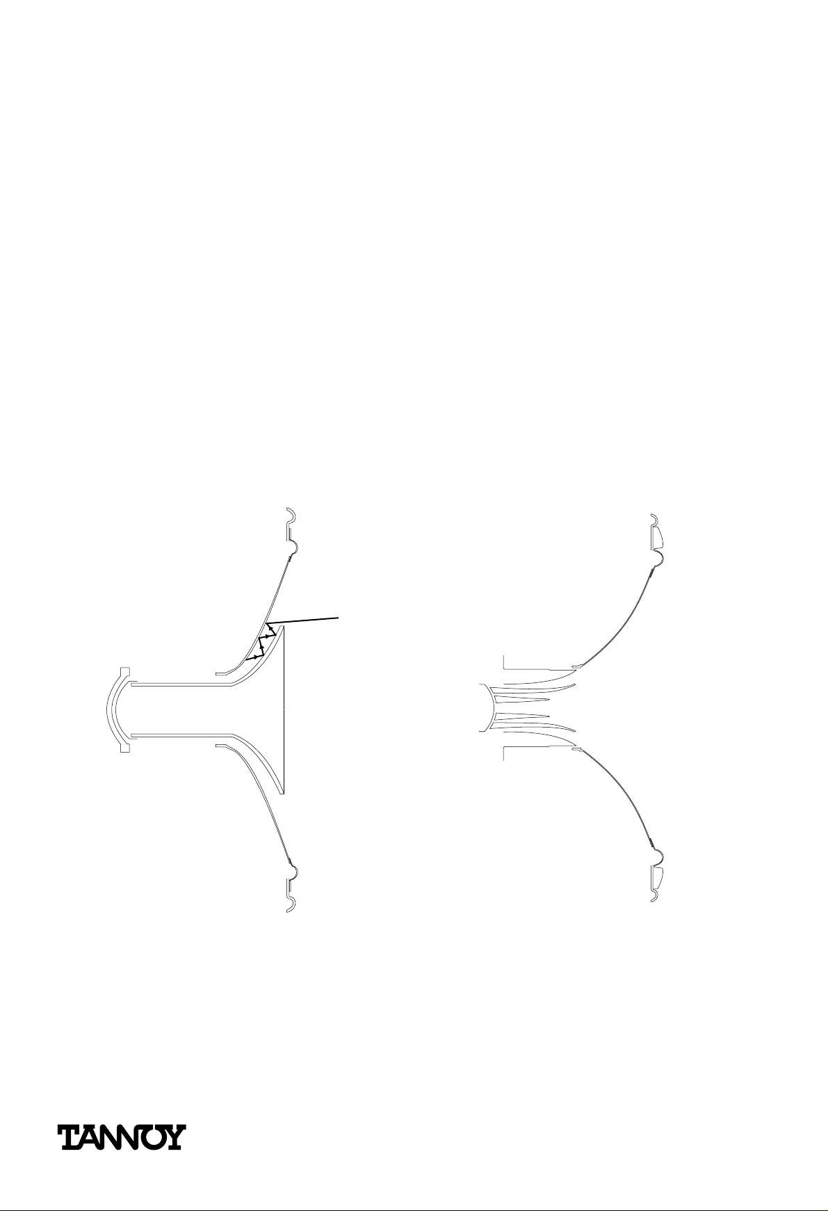
CAD waveguide – lower compression lower distortion
HF compression drive units which used a variety of separate horns always have to have one eye on
physical compatibility, they have to use a standardised thr oat diameters (usually 1” or 2”). This is
regardless of what the designer would prefer to use in the ideal world.
By being free of this requirement, the HF waveguide system used by the Tannoy Dual Concentric can
be designed purely to meet the requirements of the whole loudspeaker’s perfor mance.
The new wave guide developed using sophisticated computer aided design technique is a lot more
open in structure, substantially decr easing the compression ratio. Lower compr ession means that
the diaphragm can make larger excursions, with lower even order har monic distortion.
Significantly Lower HF Compression Ratio Driver
Standard Throat
Matching Diameter
High Compression
Throat Area
SMALLER SPACING:
LESS POWER HANDLI
LESS EXCURSION
MORE DISTORTION
Diaphragm
LARGER SPACING:
Typical Coaxial with Slotted Phase Plug
MORE POWER HANDLING
MORE EXCURSION
LESS 2ND HARMONIC
Tannoy Dual Concentric
‘Tulip’ Waveguide
• An integrated approach can concentrate on solving driver problems.
• Much lower HF compression ratios gives lower distor tion, higher power handling and SPLs.
© Tannoy Ltd May 1992/June 1996 Part No. 6483 0283
®
Page 18
Page 19

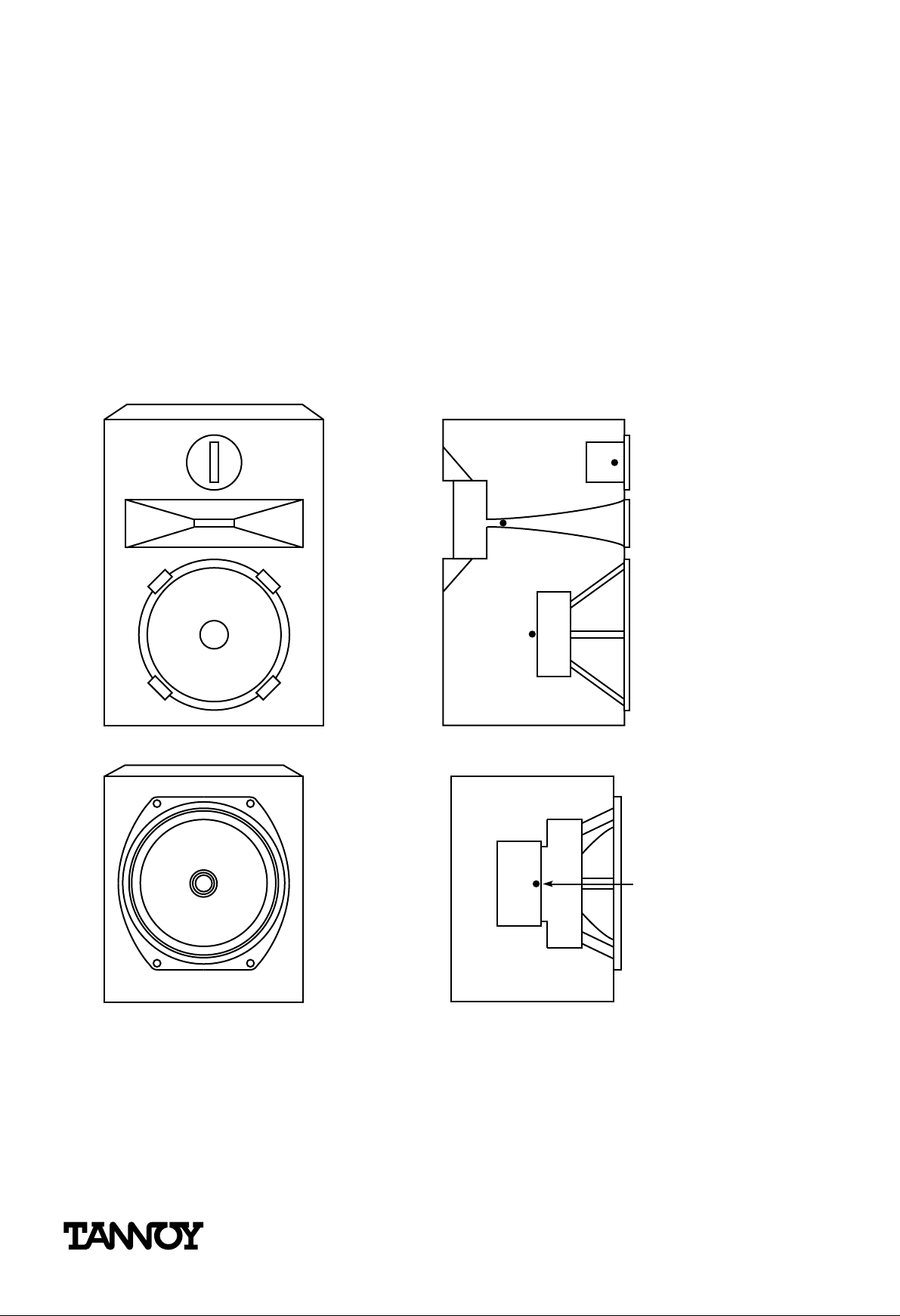
Horn and cone – a single system
The Tannoy Dual Concentric uses the cone as an extension of the HF horn. By working this way, integrating the cone and HF horn, there is no jump in acoustic impedance as the HF wavefront leaves the
horn. The acoustic load impedance offered to the driver changes smoothly and gently. Smooth
acoustic impedance means that there will be no large swings in electrical impedance, so making the
speaker easier to drive.
LF Cone is an Extension of the HF Waveguide
HF horn
HF mouth diameter
Large mouth = Low cutoff
• Designing the cone as an extension of the HF horn ensures a smooth acoustic impedance
transition.
• Smoother acoustic impedance means smoother electrical impedance curves and more pr edictable powering requirements, making better use of the available amplifier power.
© Tannoy Ltd May 1992/June 1996 Part No. 6483 0283
®
Page 19
Page 20

Smoother impedance and easier to drive
Speakers are driven by voltage swings produced by the amplifier – the greater the voltage swing, the
greater the cone excursion, the louder the sound.
However, the current drawn from the amplifier is dependant on the speaker’s impedance. As the
impedance drops then more cur rent is drawn.
Amplifiers have a finite limit to the amount of current they can deliver and moder n installation amplifiers integrate protection systems to stop the amplifier trying to deliver too much current.
These have varying ef fects from r estricting the dynamic range, to temporarily shutting down. So it is
impor tant that the loudspeaker pr esents a smooth impedance curve with no dramatic dips, that
might push an already hard working amplifier into protection mode.
The Tannoy Dual Concentric Of fers Smooth and Gentle Impedance Changes
I
z1
Impedance of Typical Coaxial
Peaks due to
discontinuity
F
S
Discontinuity
in HF horn
20 kHz1 kHz
No discontinuity
in HF horn
I
z1
Impedance of Dual Concentric
Low Q fundamental
resonance only
F
S
20 kHz1 kHz
• Smoother impedance for less strain on the amplifiers.
• Better controlled impedance dips give less likelihood of amplifier protection circuits operating.
• Smooth impedance makes for more accurate prediction of power requir ements, less incentive to over-specify amplifier powers.
© Tannoy Ltd May 1992/June 1996 Part No. 6483 0283
®
Page 20
Page 21

Higher heat dissipation – more accurate dynamics
Because of the large magnets and pole pieces used in the Tannoy Dual Concentric, the driver has a
high thermal mass. This, linked with the use of magnetic fluid, gives better control over the coil’s
temperature.
If the coil temperature increases significantly then its resistance goes up, it draws less cur r ent, and
the upper levels of dynamic range are compressed. For a loudspeaker designed to accurately reproduce live performance, it is critical to have accurate dynamic performance if the sound isn’t going to
become flat and uninteresting.
Keeping the temperature stable also helps with reliability, especially at high power levels.
High Thermal Mass and Power Dissipation
Heat dissipation from large area of LF and HF magnets and chassis
• Lower acoustic compression for better live sound.
• Better heat dissipation means better long term reliability.
• Better heat dissipation – greater tolerance of accidental overdriving.
© Tannoy Ltd May 1992/June 1996 Part No. 6483 0283
®
Page 21
Page 22

Addressing the crossover ar ea
The crossover area is critical to the performance of a loudspeaker system, and when separate drive
units are used to cover the audio spectrum, this is the one ar ea that the design engineer has least
control over.
The Tannoy Dual Concentric is designed as an entire system. This means that problems, like the
smooth transition of level and dispersion over the crossover area, can be resolved in the driver
design.
As the two driver sections are designed to work inseparably Tannoy designers are able to modify the
physical characteristics of the cone and diaphragms so that they work in a symbiotic manner, generating a perfectly even amplitude and dispersion characteristic at the crossover area.
Typical Coaxial Response Showing LF and HF Drivers Before Crossover Equalisation
HF
LF
Sound pressure (dB)
10 100 10000 200001000
Frequency (Hz)
Tannoy Dual Concentric Showing Before Crossover Equalisation
LF HF
Sound pressure (dB)
10 100 10000 200001000
Frequency (Hz)
• An integrated driver design can address major problems at the design/manufacturing stage.
• Problems associated with the crossover area can be designed out in an integrated driver.
© Tannoy Ltd May 1992/June 1996 Part No. 6483 0283
®
Page 22
Page 23

Better driver integration – simpler crossovers
In the Dual Concentric, the integration of LF/HF drive units and horn is predeter mined in the design
stage. There are no unpredictable elements, such as how far the HF and LF drive units are placed
away from each other and how coherent they are.
Consequently the crossover has to deal only with the smooth filtering of the signal to each section of
the loudspeaker. It does not have to add components to deal with time anomalies in the crossover
area and it does not need components to delay one of the signal paths. It also does not need to
apply steep filtering to reduce the size of the crossover area.
Simpler crossovers are more reliable and do less damage to the sound especially at high powers.
When active crossovers are being used they result in a better response shape, and ther e is no
requirement for additional digital delay circuits.
Since there are no ‘variables’ when using a Dual Concentric there is less crossover alignment work
to be done on site. This will substantially reduce the time spent equalising and remove any need to
introduce and then adjust HF delay line times.
Typical Coaxial Crossover Incorporating HF Time Delay
HF In
Typical Tannoy Dual Concentric Crossover
HF In
HF
• Full control of the speaker design makes crossover design simpler.
• Simple crossovers sound better.
• Simple crossovers are less expensive.
• Simple crossovers take less time to set up on site.
© Tannoy Ltd May 1992/June 1996 Part No. 6483 0283
®
Page 23
Page 24

DUAL CONCENTRICS – HISTORY IN THE MAKING
It is interesting to see increasing numbers of our competitors moving slowly towards the idea
of a point source system. They are reducing box size, squeezing drive units closer together
and using delay lines to ‘recreate’ a coincident source.
Tannoy has always believed that the obvious and natural way of solving the problems of separated drive units is not to separate them in the first place.
Throwing more and more technology at the pr oblem can cause more difficulties than it
cures.
But Tannoy’s Dual Concentric is more than a Point Source, it is a fully integrated full range
loudspeaker system that maintains complete control over the system design.
The principle has been established for decades, but the technology and materials are more
advanced than any of the competition.
The signal being fed to the speaker is completely homogeneous. Splitting it into dif fer ent frequencies to be delivered from different positions in space, can only create problems.
The Dual Concentric is simply the right way to deliver a homogeneous signal.
© Tannoy Ltd May 1992/June 1996 Part No. 6483 0283
®
Page 24
 Loading...