

Page 1
CMS65 ICT ASSEMBLY INSTRUCTIONS
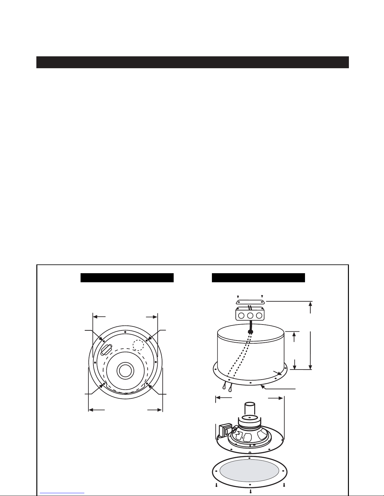
MODEL WITH TRANSFORMER
(SEE FIG. 2)
The RED and BLACK wires are connected
to the transformer as follows:
The BLACK lead to the transformer
primary "common" lead. The RED lead is
connected to the desired wattage tap.
WITHOUT TRANSFORMER
The RED and BLACK wires inside the
enclosure connect directly to the loudspeaker. The RED wire connects to the
speaker terminal with the red dot.
(Positive terminal).
The BLACK lead connects to the
unmarked terminal. (Negative terminal).
INSTALLING THE SPEAKER/SUB
PLATE ASSEMBLY
After connecting the RED and BLACK
leads to the speaker/sub assembly can
be attached to the enclosure.
Fasten the sub plate to the enclosure by
inserting the silver screws in the holes
labeled 1, 2, 3, and 4, as shown on Fig.
1.
The four remaining holes are used to
fasten the grille to the enclosure. Use the
white painted screws provided. Do not
over-tighten screws.
Note: A tile bridge is required for most
applications.
TO BOX INSTALLED
95/8"
246 mm
75/8"
194 mm
MOUNTING
FLANGE
CAN
EXTENSION
7
/16" 11.5 mm
12" 305 mm
HOLE
CUTOUT DIA.
FIGURE 2
FIGURE 1
CAN DIA.
117/8" 300 mm
1
2
3
13
1
/4" 335 mm
MOUNTING FLANGE DIA.
4
 Loading...